EP0458416B1 - Einrichtung und Verfahren zum Einführen von Katalysatorteilchen in ein bewegliches Bett - Google Patents
Einrichtung und Verfahren zum Einführen von Katalysatorteilchen in ein bewegliches Bett Download PDFInfo
- Publication number
- EP0458416B1 EP0458416B1 EP91201203A EP91201203A EP0458416B1 EP 0458416 B1 EP0458416 B1 EP 0458416B1 EP 91201203 A EP91201203 A EP 91201203A EP 91201203 A EP91201203 A EP 91201203A EP 0458416 B1 EP0458416 B1 EP 0458416B1
- Authority
- EP
- European Patent Office
- Prior art keywords
- catalyst particles
- housing
- passage
- introducing
- catalyst
- Prior art date
- Legal status (The legal status is an assumption and is not a legal conclusion. Google has not performed a legal analysis and makes no representation as to the accuracy of the status listed.)
- Expired - Lifetime
Links
- 239000003054 catalyst Substances 0.000 title claims description 99
- 239000002245 particle Substances 0.000 title claims description 82
- 239000012530 fluid Substances 0.000 claims description 38
- 238000000034 method Methods 0.000 claims description 24
- 238000005243 fluidization Methods 0.000 claims description 19
- 238000011144 upstream manufacturing Methods 0.000 claims description 9
- 238000004523 catalytic cracking Methods 0.000 claims description 5
- 238000005336 cracking Methods 0.000 claims description 3
- 238000004231 fluid catalytic cracking Methods 0.000 description 15
- 239000007789 gas Substances 0.000 description 13
- 239000003921 oil Substances 0.000 description 11
- 239000004215 Carbon black (E152) Substances 0.000 description 7
- 229930195733 hydrocarbon Natural products 0.000 description 7
- 150000002430 hydrocarbons Chemical class 0.000 description 7
- 230000008929 regeneration Effects 0.000 description 4
- 238000011069 regeneration method Methods 0.000 description 4
- 238000006243 chemical reaction Methods 0.000 description 3
- 230000000052 comparative effect Effects 0.000 description 2
- 230000003068 static effect Effects 0.000 description 2
- 229910021536 Zeolite Inorganic materials 0.000 description 1
- HNPSIPDUKPIQMN-UHFFFAOYSA-N dioxosilane;oxo(oxoalumanyloxy)alumane Chemical compound O=[Si]=O.O=[Al]O[Al]=O HNPSIPDUKPIQMN-UHFFFAOYSA-N 0.000 description 1
- 230000005484 gravity Effects 0.000 description 1
- 239000000203 mixture Substances 0.000 description 1
- 239000003079 shale oil Substances 0.000 description 1
- 239000002002 slurry Substances 0.000 description 1
- 238000004230 steam cracking Methods 0.000 description 1
- 239000010457 zeolite Substances 0.000 description 1
Images

Classifications
-
- C—CHEMISTRY; METALLURGY
- C10—PETROLEUM, GAS OR COKE INDUSTRIES; TECHNICAL GASES CONTAINING CARBON MONOXIDE; FUELS; LUBRICANTS; PEAT
- C10G—CRACKING HYDROCARBON OILS; PRODUCTION OF LIQUID HYDROCARBON MIXTURES, e.g. BY DESTRUCTIVE HYDROGENATION, OLIGOMERISATION, POLYMERISATION; RECOVERY OF HYDROCARBON OILS FROM OIL-SHALE, OIL-SAND, OR GASES; REFINING MIXTURES MAINLY CONSISTING OF HYDROCARBONS; REFORMING OF NAPHTHA; MINERAL WAXES
- C10G11/00—Catalytic cracking, in the absence of hydrogen, of hydrocarbon oils
- C10G11/14—Catalytic cracking, in the absence of hydrogen, of hydrocarbon oils with preheated moving solid catalysts
- C10G11/18—Catalytic cracking, in the absence of hydrogen, of hydrocarbon oils with preheated moving solid catalysts according to the "fluidised-bed" technique
-
- B—PERFORMING OPERATIONS; TRANSPORTING
- B01—PHYSICAL OR CHEMICAL PROCESSES OR APPARATUS IN GENERAL
- B01J—CHEMICAL OR PHYSICAL PROCESSES, e.g. CATALYSIS OR COLLOID CHEMISTRY; THEIR RELEVANT APPARATUS
- B01J8/00—Chemical or physical processes in general, conducted in the presence of fluids and solid particles; Apparatus for such processes
- B01J8/0015—Feeding of the particles in the reactor; Evacuation of the particles out of the reactor
- B01J8/0025—Feeding of the particles in the reactor; Evacuation of the particles out of the reactor by an ascending fluid
Definitions
- the present invention relates to an apparatus and a process for introducing catalyst particles into a moving bed of catalyst.
- catalyst particles can advantageously be brought in plug-flow at a far earlier stage, i.e. when the riser has only been passed over a very short distance, by employing as liftpot an apparatus comprising a housing provided with a particular passage for catalyst particles in the downstream part thereof.
- improved reaction patterns can be obtained in the reactor, resulting in improved yields of valuable products.
- the present invention therefore relates to an apparatus for introducing catalyst particles into a moving bed of catalyst, which apparatus comprises a housing, in the upstream part thereof having inlet means for introducing catalyst particles into the housing and having fluidization means, and in the downstream part thereof having a passage for the catalyst particles defined between directing means and the inner wall of the housing and/or between adjacent directing means facing each other, wherein the passage has a narrowing part and a narrow part in downstream direction and wherein the directing means are not axially displaceable.
- the housing comprises a single passage defined between a substantially centrally arranged directing means and the inner wall of the housing.
- the single passage comprises an annular opening.
- the annular opening is suitably uninterrupted but an interrupted annular opening comprising a series of openings arranged in an annular pattern can also be applied.
- a single (annular) passage is preferred, it should be understood that a plurality of passages can be arranged in such a way that the housing comprises more than one annular opening, for instance three annular openings to allow the catalyst particles to pass through.
- the passage of the apparatus according to the present invention comprises a widening part in downstream direction.
- the housing of the apparatus according to the present invention comprises directing means having a widening part, a wide part and a narrowing part in downstream direction and wherein the directing means are not axially displaceable.
- the directing means has a diamond-shape vertical cross-section and is symmetrically arranged in respect to its vertical axis.
- the apparatus according to the present invention comprises fluid supply means having at least one fluid outlet opening debouching in the widening part or at or near the narrow part of the passage.
- the fluid outlet opening is arranged downstream with respect to the narrow part of the passage.
- the fluid supply means comprises at least one device arranged onto the wall of the housing downstream with respect to the narrow part of the passage.
- such a device comprises at least one supply means of which the wall comprises openings.
- the fluid to be supplied to the housing can thus be introduced into the supply means and mixed with an at least partly surrounding gas which may enter under pressure the supply means through the openings in the wall thereof.
- the apparatus according to the present invention comprises more than one device as described hereinbefore, for instance four of these devices.
- the apparatus according to the present invention comprises more than one device as described hereinbefore, for instance four of these devices.
- EP-A-423 876 we refer to EP-A-423 876.
- the housing comprises directing means comprising fluid supply means which extend from the bottom end part of the housing.
- the fluid outlet opening can suitably be arranged in the narrowing part of the directing means in downstream direction.
- the fluid outlet opening of the fluid supply means can be an annular opening in the downstream end part of the fluid supply means, or can be a number of openings arranged in an annular pattern in the downstream end part of the fluid supply means.
- a directing means is arranged onto the inner wall of the housing whereby the passage is defined between said directing means and the fluid supply means extending from the bottom end part of the housing as described hereinabove.
- the housing comprises a grid of directing means between which passages are defined having a narrowing part and a narrow part.
- the apparatus according to the present invention is suitably provided with both directing means in the form of fluid supply means which extend from the bottom end part of the housing and fluid supply means in the form of devices which are arranged onto the wall of the housing having a fluid outlet opening along the widening part of the passage.
- the housing comprises a directing means in the form of a single tubular fluid supply means substantially centrally arranged in the bottom end part thereof.
- the annular passage is of such a size that the catalyst particles pass the opening at a velocity which is at least 0.25 times the velocity of the catalyst particles in the riser reactor.
- the catalyst particles pass the opening at a velocity which is at least 0.5 times the velocity of the catalyst particles in the riser reactor.
- the apparatus comprises inlet means for introducing catalyst particles into the housing which inlet means comprises a fluidized bed of catalyst particles.
- the inlet means suitably communicates with a fluidized bed of catalyst particles, for instance the bottom part of a stripper vessel or a regeneration vessel.
- catalyst particles are advantageously pre-accelerated before they pass the passage by using the static head at the bottom of the stripper vessel or regeneration vessel.
- the inlet means comprising the fluidized bed of catalyst particles comprises fluidization means (e.g. in the form of a perforated plate or ring-shaped or annular fluidization means) provided with regularly spaced fluidization gas openings through which a fluidization gas can be introduced in the inlet means.
- fluidization gases include steam and fluid catalytic cracking off gas.
- the inlet means comprising the fluidized bed of catalyst particles is preferably of tubular form and horizontally arranged.
- the inlet means of catalyst particles is arranged in such a way that the length thereof is from 2 to 3 times the diameter of the tubular inlet means, and the housing/inlet means diameter ratio is suitably in the range from 1 to 5.
- the housing has been provided with substantially horizontally internals upstream the passage for the catalyst particles.
- a homogeneous flow of catalyst particles is established upstream the passage of the catalyst particles.
- a major advantage of the apparatus according to the present invention is that during operation a stream of catalyst particles obtains an optimal flow mode, i.e. plugflow, at a far shorter distance from the passage for the catalyst particles than conventionally is the case, resulting in improved reaction patterns in the reactor and enabling the use of shorter reactors.
- the apparatus according to the present invention is advantageously used in fluid catalytic cracking operations for introducing catalyst particles in a riser reactor.
- the present invention further relates to an apparatus for catalytically cracking of hydrocarbonaceous feedstocks which comprises a riser reactor the bottom end part of which is connected to an apparatus for introducing catalyst particles as described hereinbefore.
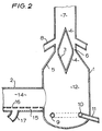
- the bottom part of the fluid catalytic cracking reactor as depicted in Figure 1 comprises a substantially vertically housing (1) provided with an inlet means (2) for introducing catalyst particles, a directing means (3) arranged in the downstream part of the housing, a passage (4) defined between the directing means (3) and the inner wall of the housing (5) comprising an annular opening (6) and having a narrowing part, a narrow part and a widening part in downstream direction, a moving bed of catalyst (7) and fluid supply means in the form of devices (8) (of which only two have been shown) for introducing a hydrocarbon oil into the riser reactor.
- the riser reactor furthermore comprises fluidization means (9), for instance in the form of a ring-shaped or annular fluidization means, provided with regularly spaced fluidization gas openings (e.g. nozzles (10)) through which a fluidization gas, for instance steam, introduced via fluidization gas inlet means (11) emanates into the bottom section (12) of the reactor.
- fluidization means (9) for instance in the form of a ring-shaped or annular fluidization means, provided with regularly spaced fluidization gas openings (e.g. nozzles (10)) through which a fluidization gas, for instance steam, introduced via fluidization gas inlet means (11) emanates into the bottom section (12) of the reactor.
- the inlet means (2) for introducing catalyst particles comprises a fluidized bed of catalyst particles (14).
- the inlet means (2) furthermore preferably comprises fluidization means (15) (e.g. in the form of a perforated plate as depicted in Figure 2 or ring-shaped or annular fluidization means) provided with regularly spaced fluidization gas openings (e.g. nozzles (16)) through which a fluidization gas (e.g. steam or a fluid catalytic cracking off gas) introduced via fluidization gas inlet means (17) emanates into the fluidized bed of catalyst (14).
- fluidization means e.g. in the form of a perforated plate as depicted in Figure 2 or ring-shaped or annular fluidization means
- a fluidization gas e.g. steam or a fluid catalytic cracking off gas
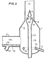
- FIG 3 another suitable embodiment of the apparatus in accordance with the present invention is depicted which comprises directing means in the form of a fluid supply means (13) which extends from the bottom end part of the reactor and comprises fluid outlet openings (18) in its narrowing part (of which only two have been shown).
- directing means in the form of a fluid supply means (13) which extends from the bottom end part of the reactor and comprises fluid outlet openings (18) in its narrowing part (of which only two have been shown).
- the invention further relates to a process for introducing catalyst particles into a moving bed, which process comprises introducing a stream of catalyst particles into the upstream part of a housing and allowing the catalyst particles to pass in downstream direction through a passage defined between directing means and the inner wall of the housing and/or between adjacent directing means facing each other, wherein the passage has a narrowing part and a narrow part in downstream direction and wherein the directing means are not axially displaceable.
- the catalyst particles are allowed to pass through a single passage which is defined between a substantially centrally arranged directing means and the inner wall of the housing.
- the catalyst particles are allowed to pass through a single passage comprising an annular opening.
- any of the directing means can be applied as described hereinbefore.
- the apparatus used in the process according to the present invention preferably comprises a passage having a widening part in downstream direction.
- the process in accordance with the present invention is carried out in such a way that a stream of fluidized catalyst particles enters the housing.
- the inlet means preferably comprises a fluidized bed of catalyst particles which communicates substantially horizontally with the bottom part of a catalyst stripper vessel or a regeneration vessel.
- the catalyst particles are advantageously pre-accelerated before passing the passage by use of the static head at the bottom of the stripper vessel or regeneration vessel.
- a pressure drop is maintained over the passage(s) of at least 0.2 bar.
- a pressure drop is maintained over the passage(s) of at least 0.3 bar.
- the stream of catalyst particles passes the opening at a velocity of at least 0.25 times the velocity which the catalyst particles have in the riser reactor.
- the catalyst particles pass the opening at a velocity of at least 0.5 times the velocity of the catalyst particles in the riser reactor.
- the fluidized stream of catalyst particles is introduced into the upstream part of housing.
- fluid is introduced downstream with respect to the narrow part, e.g. along the widening part of the passage.
- the narrow part e.g. along the widening part of the passage.
- the fluid is introduced with respect to the narrow part of the passage by means of devices which are arranged onto the wall of the housing.
- the process according to the present invention can advantageously be used for introducing catalyst particles in the riser reactor of a fluid catalytic cracking unit.
- the present invention also relates to a process for catalytic cracking of a hydrocarbonaceous feedstock, wherein the feedstock is introduced into a moving bed of catalytic cracking catalyst and catalytically cracked.
- Fluids such as those applied in a catalytic cracking process are preferably mixed with the catalyst particles which are passed through the passage at a temperature from 0-800 °C, most preferably from 100-750 °C.
- the mixing of fluid and catalyst particles is preferably carried out at elevated pressure, most preferably from 1-100 bar and in particular from 2-50 bar.
- a fluid catalytic cracking process is preferably carried out at a temperature from 400-800 °C and a pressure from 1-10 bar.
- Such a process is advantageously carried out in a riser reactor for fluid catalytic cracking of a hydrocarbonaceous feedstock as referred to hereinbefore and partly depicted in Figures 1-3 by introducing a stream of catalyst particles originating from a catalyst regenerator by means of the present apparatus.
- the catalyst/fluid weight ratio to be applied in the process according to the present invention can vary within a wide range, and may be up to 100. It will be understood that the catalyst/fluid weight ratio of the stream of catalyst particles will have an influence upon the width of the passage for the catalyst particles. The higher the catalyst/fluid weight ratio of the stream of catalyst particles introduced into the housing the larger the width of the passage for the catalyst particles.
- a stream of catalyst particles (e.g. originating from a catalyst regenerator) is introduced through inlet means (2) into the bottom section (12) of the riser reactor.
- the catalyst particles are transported upwardly by means of for instance steam introduced via line (11) into ring-shaped or annular fluidization means (9) provided with regularly spaced nozzles (10).
- the upwardly fluidized mass of catalyst particles is subsequently advantageously accelerated over the passage (4) having a narrowing part, a narrow part and a widening part in downstream direction, introduced into the moving bed of catalyst (7) and excellently mixed with the stream of hydrocarbon oil which enters under pressure with a high velocity the reactor via the devices (8) or via fluid supply means (13) through the fluid outlet openings (18).
- the use of the apparatus in accordance with the present invention results in a very uniform mixing of the accelerated catalyst particles and the hydrocarbon oil and an optimal flow mode of the stream of catalyst particles at a very early stage in the riser reactor. As a result of this a very attractive increase in gasoline yield can be obtained.
- the hydrocarbon oil which can suitably be converted in a fluid catalytic cracking process using the present apparatus comprises heavy hydrocarbon oils, for instance atmospheric or vacuum distillates, cycle oils and slurry oils, deasphalted oils, atmospheric and vacuum residues, thermally cracked residues, asphalts originating from various kinds of deasphalting processes, synthetic residues and hydrocarbon oils originating from hydroconversion processes, tar sands and shale oils of any source, and/or any mixture thereof.
- heavy hydrocarbon oils for instance atmospheric or vacuum distillates, cycle oils and slurry oils, deasphalted oils, atmospheric and vacuum residues, thermally cracked residues, asphalts originating from various kinds of deasphalting processes, synthetic residues and hydrocarbon oils originating from hydroconversion processes, tar sands and shale oils of any source, and/or any mixture thereof.
- the present invention is illustrated by means of the following Example.
- a fluid catalytic cracking experiment is carried out as follows.
- a stream of fluidized catalyst particles (regenerated zeolite Y catalyst particles) is introduced into a fluid catalytic cracking reactor comprising a liftpot as depicted in Figure 2 at a temperature of 700 °C and a pressure of 3.3 bar, and accelerated over the passage (4).
- the accelerated stream of catalyst particles is subsequently mixed with a stream of hydrocarbon oil having the properties as shown in Table 1 which oil is introduced via devices (8) at a temperature of 260 °C and a pressure of 6 bar.
- the catalyst particles enter the riser reactor at a velocity of 15 m/s.
- the riser reactor is operated at a temperature of 520 °C and a pressure of 3 bar.
- a comparative experiment is carried out in substantially the same manner as described hereinabove except that a fluid catalytic cracking reactor is used comprising a conventional liftpot.
- a fluid catalytic cracking reactor comprising a conventional liftpot.
- 1 % wt more gasoline (C5 - 221 °C) is obtained, when compared with the comparative experiment.
Landscapes
- Chemical & Material Sciences (AREA)
- Organic Chemistry (AREA)
- Chemical Kinetics & Catalysis (AREA)
- Oil, Petroleum & Natural Gas (AREA)
- Engineering & Computer Science (AREA)
- General Chemical & Material Sciences (AREA)
- Devices And Processes Conducted In The Presence Of Fluids And Solid Particles (AREA)
- Production Of Liquid Hydrocarbon Mixture For Refining Petroleum (AREA)
- Exhaust Gas Treatment By Means Of Catalyst (AREA)
- Catalysts (AREA)
Claims (20)
- Vorrichtung zum Einführen von Katalysatorteilchen in ein bewegtes Katalysatorbett, mit einem Gehäuse, in dessen stromaufwärtigem Teil Einlaßmittel zum Einführen der Katalysatorteilchen in das Gehäuse und Fluidisiermittel vorgesehen sind, und in dessen stromabwärtigem Teil ein Durchgang für die Katalysatorteilchen vorgesehen ist, der zwischen Leitmitteln und der Innenwand des Gehäuses und/oder zwischen benachbarten, einander zugekehrten Leitmitteln gebildet wird, wobei der Durchgang in stromabwärtiger Richtung einen sich verjüngenden Teil und einen engen Teil aufweist, dadurch gekennzeichnet, daß die Leitmittel nicht axial versetzbar sind.
- Vorrichtung nach Anspruch 1, bei welcher das Gehäuse einen einzigen Durchgang aufweist, der zwischen im wesentlichen zentral angeordneten Leitmitteln und der Innenwand des Gehäuses angeordnet ist.
- Vorrichtung nach Anspruch 2, bei welcher der Durchgang eine ringförmige Öffnung aufweist.
- Vorrichtung nach einem der Ansprüche 1-3, bei welcher der Durchgang einen sich in stromabwärtiger Richtung erweiternden Teil aufweist.
- Vorrichtung nach einem der Ansprüche 1-4, bei welcher das Gehäuse Leitmittel mit einem sich in stromabwärtiger Richtung erweiternden Teil, einem weiten Teil und einem sich verengenden Teil aufweist.
- Vorrichtung nach einem der Ansprüche 1-5, bei welcher das Gehäuse Fluidzufuhrmittel aufweist, die zumindest eine Fluidauslaßöffnung haben, welche stromabwärts des engen Teiles des Durchganges angeordnet sind.
- Vorrichtung nach Anspruch 6, bei welcher die Fluidzufuhrmittel zumindest eine Einrichtung aufweisen, die an der Wand des Gehäuses angeordnet ist.
- Vorrichtung nach einem der Ansprüche 1-7, bei welcher die Leitmittel Fluidzufuhrmittel aufweisen, die sich vom unteren Endteil des Gehäuses wegerstrecken.
- Vorrichtung nach Anspruch 8, bei welcher die Fluidzufuhrmittel Fluidauslaßöffnungen aufweisen, die in Umfangsrichtung im stromabwärtigen Endteil der Fluidzufuhrmittel angeordnet sind.
- Vorrichtung nach einem der Ansprüche 1-9, bei welcher im wesentlichen horizontale Inneneinbauten im Gehäuse stromaufwärts des Durchganges für die Katalysatorteilchen angeordnet sind.
- Vorrichtung nach einem der Ansprüche 1-10, bei welcher die Einlaßmittel zum Einführen der Katalysatorteilchen ein fluidisiertes Bett von Katalysatorteilchen aufweisen.
- Vorrichtung nach Anspruch 11, bei welcher die Einlaßmittel zum Einführen der Katalysatorteilchen Fluidisiermittel aufweisen.
- Vorrichtung nach Anspruch 11 oder 12, bei welcher die Einlaßmittel zum Einführen der Katalysatorteilchen horizontal mit einem fluidisierten Bett von Katalysatorteilchen in Verbindung stehen.
- Vorrichtung nach einem der Ansprüche 11-13, bei welcher die Länge der Einlaßmittel das 2- bis 3-fache des Durchmessers der Einlaßmittel beträgt.
- Vorrichtung zum katalytischen Cracken von kohlenwasserstoffhältigen Einsatzmaterialien, mit einem Steigreaktor, dessen unterer Endteil mit einer Vorrichtung zum Einführen von Katalysatorteilchen verbunden ist, wie sie in einem der Ansprüche 1-14 beschrieben ist.
- Verfahren zum Einführen von Katalysatorteilchen in ein bewegtes Katalysatorbett, bei welchem Verfahren ein Strom von Katalysatorteilchen in den stromaufwärtigen Teil eines Gehäuses eingeführt wird und die Katalysatorteilchen in Richtung stromabwärts durch einen Durchgang strömen gelassen werden, der zwischen Leitmitteln und der Innenwand des Gehäuses und/oder zwischen benachbarten, einander zugekehrten Leitmitteln gebildet ist, wobei der Durchgang in stromabwärtiger Richtung einen sich verengenden Teil und einen engen Teil aufweist und wobei die Leitmittel axial nicht versetzbar sind.
- Verfahren nach Anspruch 16, bei welchem über dem Durchgang ein Druckabfall von zumindest 0,2 bar aufrechterhalten wird.
- Verfahren nach Anspruch 16 oder 17, bei welchem ein fluidisierter Strom von Katalysatorteilchen in den stromaufwärtigen Teil des Gehäuses eingeführt wird.
- Verfahren nach einem der Ansprüche 16-18, bei welchem Fluid in das Gehäuse stromabwärts des engen Teiles des Durchganges eingeführt wird.
- Verfahren zum katalytischen Cracken von kohlenwasserstoffhaltigem Einsatzmaterial, bei welchem das Einsatzmaterial in ein bewegtes Bett von katalytischem Crackkatalysator eingeführt wird, welches Katalysatorteilchen aufweist, die durch das Verfahren nach einem der Ansprüche 16-18 eingeführt wurden, und katalytisch gecrackt wird.
Applications Claiming Priority (2)
| Application Number | Priority Date | Filing Date | Title |
|---|---|---|---|
| GB9011407 | 1990-05-22 | ||
| GB909011407A GB9011407D0 (en) | 1990-05-22 | 1990-05-22 | Apparatus and process for producing catalyst particles into a moving bed of catalyst |
Publications (2)
| Publication Number | Publication Date |
|---|---|
| EP0458416A1 EP0458416A1 (de) | 1991-11-27 |
| EP0458416B1 true EP0458416B1 (de) | 1994-09-14 |
Family
ID=10676352
Family Applications (1)
| Application Number | Title | Priority Date | Filing Date |
|---|---|---|---|
| EP91201203A Expired - Lifetime EP0458416B1 (de) | 1990-05-22 | 1991-05-17 | Einrichtung und Verfahren zum Einführen von Katalysatorteilchen in ein bewegliches Bett |
Country Status (15)
| Country | Link |
|---|---|
| US (1) | US5205992A (de) |
| EP (1) | EP0458416B1 (de) |
| JP (1) | JP3157189B2 (de) |
| CN (1) | CN1029941C (de) |
| AR (1) | AR247831A1 (de) |
| AT (1) | ATE111506T1 (de) |
| AU (1) | AU642239B2 (de) |
| BR (1) | BR9102058A (de) |
| CA (1) | CA2042888A1 (de) |
| DE (1) | DE69103958T2 (de) |
| DK (1) | DK0458416T3 (de) |
| ES (1) | ES2064036T3 (de) |
| GB (1) | GB9011407D0 (de) |
| TW (1) | TW199114B (de) |
| ZA (1) | ZA913793B (de) |
Families Citing this family (15)
| Publication number | Priority date | Publication date | Assignee | Title |
|---|---|---|---|---|
| US5562818A (en) * | 1993-07-16 | 1996-10-08 | Uop | FCC feed injection with non-quiescent mixing |
| US5462652A (en) * | 1993-09-24 | 1995-10-31 | Uop | Short contact FCC process with catalyst blending |
| US5346613A (en) * | 1993-09-24 | 1994-09-13 | Uop | FCC process with total catalyst blending |
| US5554341A (en) * | 1994-12-12 | 1996-09-10 | Phillips Petroleum Company | Feed zone performance for a cat cracker |
| US6042717A (en) | 1997-12-05 | 2000-03-28 | Uop Llc | Horizontal FCC feed injection process |
| FR2778859B1 (fr) * | 1998-05-25 | 2000-08-11 | Total Raffinage Distribution | Procede et dispositif d'introduction de particules de catalyseur dans un reacteur de craquage catalytique a l'etat fluide |
| US6346219B1 (en) | 1998-11-20 | 2002-02-12 | Uop Llc | FCC feed injector with closure plug |
| CN1098338C (zh) * | 2000-06-12 | 2003-01-08 | 中国石油化工集团公司 | 一种加氢催化剂器外再生方法 |
| US6613290B1 (en) * | 2000-07-14 | 2003-09-02 | Exxonmobil Research And Engineering Company | System for fluidized catalytic cracking of hydrocarbon molecules |
| DE102004013019A1 (de) * | 2004-03-16 | 2005-10-06 | Sebastian Zimmer | Wirbelschichtreaktor |
| US8377387B2 (en) * | 2010-06-23 | 2013-02-19 | General Electric Company | Fluidization device for solid fuel particles |
| US20120171054A1 (en) * | 2011-01-03 | 2012-07-05 | General Electric Company | System for fluidizing solid feedstock from a solid feed pump |
| JP5823911B2 (ja) * | 2012-04-27 | 2015-11-25 | Jx日鉱日石エネルギー株式会社 | 流動接触分解装置における原料と触媒を混合する混合装置 |
| CN103446877B (zh) * | 2013-08-23 | 2016-08-10 | 中国大唐集团科学技术研究院有限公司 | 流化床反应器及其内构件 |
| US10913043B2 (en) | 2018-09-28 | 2021-02-09 | Uop Llc | Apparatuses for mixing of staged methanol injection |
Family Cites Families (14)
| Publication number | Priority date | Publication date | Assignee | Title |
|---|---|---|---|---|
| US2606104A (en) * | 1948-04-12 | 1952-08-05 | Phillips Petroleum Co | Catalyst fluidization |
| US2640731A (en) * | 1951-07-31 | 1953-06-02 | Sun Oil Co | Automatic air lift control |
| US2937988A (en) * | 1957-03-19 | 1960-05-24 | Exxon Research Engineering Co | Prevention of coking on walls of transfer line reactor |
| US4230668A (en) * | 1976-02-19 | 1980-10-28 | The Badger Company, Inc. | Process and apparatus for producing halogenated unsaturated hydrocarbons |
| DE2744360C2 (de) * | 1977-10-01 | 1979-11-15 | Basf Ag, 6700 Ludwigshafen | Kathodisch abscheidbare Elektrotachlackbindemittel |
| US4479920A (en) * | 1981-06-29 | 1984-10-30 | Torftech Limited | Apparatus for processing matter in a turbulent mass of particulate material |
| IT1150650B (it) * | 1982-03-10 | 1986-12-17 | Montedison Spa | Reattore a letto fluido |
| EP0180291A1 (de) * | 1984-10-26 | 1986-05-07 | Mobil Oil Corporation | Technik zur Mischung des Einsatzes für die katalytische Wirbelschichtspaltung von Kohlenwasserstoffölen |
| US4578183A (en) * | 1984-11-30 | 1986-03-25 | Mobil Oil Corporation | Feed mixing technique for fluidized catalytic cracking of hydrocarbon oil |
| US4853189A (en) * | 1987-01-23 | 1989-08-01 | Phillips Petroleum Company | Apparatus for conversion of oils to hydrocarbon products |
| US4820493A (en) * | 1987-05-15 | 1989-04-11 | Mobil Oil Corporation | Apparatus for mixing fluid catalytic cracking hydrocarbon feed and catalyst |
| FR2626284B1 (fr) * | 1988-01-26 | 1990-06-08 | Total France | Appareil pour le craquage catalytique en lit fluidise d'une charge d'hydrocarbures |
| FR2631857B1 (fr) * | 1988-05-24 | 1990-09-14 | Inst Francais Du Petrole | Reacteur a lit fluidise entraine comprenant un moyen de regulation du flux de particules solides et son utilisation dans un procede de craquage catalytique |
| GB8923345D0 (en) * | 1989-10-17 | 1989-12-06 | Shell Int Research | Process for the catalytic cracking of a hydrocarbon oil |
-
1990
- 1990-05-22 GB GB909011407A patent/GB9011407D0/en active Pending
-
1991
- 1991-04-23 TW TW080103161A patent/TW199114B/zh active
- 1991-04-24 AU AU75909/91A patent/AU642239B2/en not_active Ceased
- 1991-05-17 US US07/701,715 patent/US5205992A/en not_active Expired - Fee Related
- 1991-05-17 DE DE69103958T patent/DE69103958T2/de not_active Expired - Fee Related
- 1991-05-17 AT AT91201203T patent/ATE111506T1/de not_active IP Right Cessation
- 1991-05-17 DK DK91201203.6T patent/DK0458416T3/da active
- 1991-05-17 ES ES91201203T patent/ES2064036T3/es not_active Expired - Lifetime
- 1991-05-17 CA CA002042888A patent/CA2042888A1/en not_active Abandoned
- 1991-05-17 EP EP91201203A patent/EP0458416B1/de not_active Expired - Lifetime
- 1991-05-20 JP JP14261291A patent/JP3157189B2/ja not_active Expired - Fee Related
- 1991-05-20 BR BR919102058A patent/BR9102058A/pt not_active IP Right Cessation
- 1991-05-20 ZA ZA913793A patent/ZA913793B/xx unknown
- 1991-05-20 AR AR91319713A patent/AR247831A1/es active
- 1991-05-20 CN CN91103443A patent/CN1029941C/zh not_active Expired - Fee Related
Also Published As
| Publication number | Publication date |
|---|---|
| TW199114B (de) | 1993-02-01 |
| JP3157189B2 (ja) | 2001-04-16 |
| AR247831A1 (es) | 1995-04-28 |
| AU642239B2 (en) | 1993-10-14 |
| DK0458416T3 (da) | 1994-10-17 |
| ZA913793B (en) | 1992-02-26 |
| EP0458416A1 (de) | 1991-11-27 |
| ES2064036T3 (es) | 1995-01-16 |
| AU7590991A (en) | 1991-11-28 |
| CN1056638A (zh) | 1991-12-04 |
| GB9011407D0 (en) | 1990-07-11 |
| DE69103958T2 (de) | 1995-01-26 |
| ATE111506T1 (de) | 1994-09-15 |
| CA2042888A1 (en) | 1991-11-23 |
| BR9102058A (pt) | 1991-12-24 |
| JPH06315620A (ja) | 1994-11-15 |
| US5205992A (en) | 1993-04-27 |
| CN1029941C (zh) | 1995-10-11 |
| DE69103958D1 (de) | 1994-10-20 |
Similar Documents
| Publication | Publication Date | Title |
|---|---|---|
| EP0458416B1 (de) | Einrichtung und Verfahren zum Einführen von Katalysatorteilchen in ein bewegliches Bett | |
| US4057397A (en) | System for regenerating fluidizable catalyst particles | |
| US4795547A (en) | Process for contacting particulate solids with a fluid | |
| US3246960A (en) | Catalytic conversion apparatus | |
| KR100939503B1 (ko) | 하향류 접촉분해 반응기 및 이의 용도 | |
| JP3953945B2 (ja) | 接触分解反応再生システム | |
| US4650566A (en) | FCC reactor multi-feed nozzle system | |
| JPH0623301A (ja) | ライザ・サイクロン分離器 | |
| CN111484387B (zh) | 一种含有石脑油的原料转化为低碳烯烃和/或芳烃的方法 | |
| US4808383A (en) | FCC reactor multi-feed nozzle system | |
| US6146519A (en) | Gas solid contact riser with redistribution | |
| US3894936A (en) | Conversion of hydrocarbons with {37 Y{38 {0 faujasite-type catalysts | |
| CN110691643A (zh) | 用于具有流化床的脱氢反应器的催化剂和输送气体分配器 | |
| EP0239171A2 (de) | Apparat und Verfahren zum Mischen von Flüssigkeiten | |
| CN113366090A (zh) | 使用混合的废催化剂和再生催化剂催化裂解石脑油的系统 | |
| RU2002795C1 (ru) | Способ каталитического крекинга нефт ного масла | |
| US3475326A (en) | Transfer line apparatus and method | |
| US4853189A (en) | Apparatus for conversion of oils to hydrocarbon products | |
| US4960502A (en) | Process for conversion of oils to hydrocarbon products | |
| US5160706A (en) | Process for the catalytic cracking of a hydrocarbon oil | |
| EP1456325A1 (de) | Verfahren zur regenerierung von fcc gebrauchtem katalysator | |
| JPH0263547A (ja) | 固体粒子流調節手段を備えたエントレインメント流動床反応器およびそれの使用法 | |
| CN112745887B (zh) | 一种用于粗重芳回炼混合芳烃的提升管反应器 | |
| US4541921A (en) | Method and apparatus for regenerating cracking catalyst | |
| CN111484386B (zh) | 一种含有石脑油的原料转化装置 |
Legal Events
| Date | Code | Title | Description |
|---|---|---|---|
| PUAI | Public reference made under article 153(3) epc to a published international application that has entered the european phase |
Free format text: ORIGINAL CODE: 0009012 |
|
| AK | Designated contracting states |
Kind code of ref document: A1 Designated state(s): AT BE CH DE DK ES FR GB IT LI NL SE |
|
| 17P | Request for examination filed |
Effective date: 19920318 |
|
| 17Q | First examination report despatched |
Effective date: 19921021 |
|
| GRAA | (expected) grant |
Free format text: ORIGINAL CODE: 0009210 |
|
| AK | Designated contracting states |
Kind code of ref document: B1 Designated state(s): AT BE CH DE DK ES FR GB IT LI NL SE |
|
| REF | Corresponds to: |
Ref document number: 111506 Country of ref document: AT Date of ref document: 19940915 Kind code of ref document: T |
|
| REG | Reference to a national code |
Ref country code: DK Ref legal event code: T3 |
|
| REF | Corresponds to: |
Ref document number: 69103958 Country of ref document: DE Date of ref document: 19941020 |
|
| ITF | It: translation for a ep patent filed | ||
| ET | Fr: translation filed | ||
| REG | Reference to a national code |
Ref country code: ES Ref legal event code: FG2A Ref document number: 2064036 Country of ref document: ES Kind code of ref document: T3 |
|
| EAL | Se: european patent in force in sweden |
Ref document number: 91201203.6 |
|
| PLBE | No opposition filed within time limit |
Free format text: ORIGINAL CODE: 0009261 |
|
| STAA | Information on the status of an ep patent application or granted ep patent |
Free format text: STATUS: NO OPPOSITION FILED WITHIN TIME LIMIT |
|
| 26N | No opposition filed | ||
| PGFP | Annual fee paid to national office [announced via postgrant information from national office to epo] |
Ref country code: CH Payment date: 19960806 Year of fee payment: 6 |
|
| PGFP | Annual fee paid to national office [announced via postgrant information from national office to epo] |
Ref country code: AT Payment date: 19970422 Year of fee payment: 7 |
|
| PG25 | Lapsed in a contracting state [announced via postgrant information from national office to epo] |
Ref country code: CH Free format text: LAPSE BECAUSE OF NON-PAYMENT OF DUE FEES Effective date: 19970531 Ref country code: LI Free format text: LAPSE BECAUSE OF NON-PAYMENT OF DUE FEES Effective date: 19970531 |
|
| REG | Reference to a national code |
Ref country code: CH Ref legal event code: PL |
|
| PG25 | Lapsed in a contracting state [announced via postgrant information from national office to epo] |
Ref country code: AT Free format text: LAPSE BECAUSE OF NON-PAYMENT OF DUE FEES Effective date: 19980517 |
|
| PGFP | Annual fee paid to national office [announced via postgrant information from national office to epo] |
Ref country code: SE Payment date: 20000404 Year of fee payment: 10 Ref country code: DK Payment date: 20000404 Year of fee payment: 10 |
|
| PGFP | Annual fee paid to national office [announced via postgrant information from national office to epo] |
Ref country code: BE Payment date: 20000505 Year of fee payment: 10 |
|
| PGFP | Annual fee paid to national office [announced via postgrant information from national office to epo] |
Ref country code: ES Payment date: 20000519 Year of fee payment: 10 |
|
| PGFP | Annual fee paid to national office [announced via postgrant information from national office to epo] |
Ref country code: NL Payment date: 20000526 Year of fee payment: 10 |
|
| PG25 | Lapsed in a contracting state [announced via postgrant information from national office to epo] |
Ref country code: DK Free format text: LAPSE BECAUSE OF NON-PAYMENT OF DUE FEES Effective date: 20010517 |
|
| PG25 | Lapsed in a contracting state [announced via postgrant information from national office to epo] |
Ref country code: ES Free format text: LAPSE BECAUSE OF NON-PAYMENT OF DUE FEES Effective date: 20010518 Ref country code: SE Free format text: LAPSE BECAUSE OF NON-PAYMENT OF DUE FEES Effective date: 20010518 |
|
| PG25 | Lapsed in a contracting state [announced via postgrant information from national office to epo] |
Ref country code: BE Free format text: LAPSE BECAUSE OF NON-PAYMENT OF DUE FEES Effective date: 20010531 |
|
| BERE | Be: lapsed |
Owner name: SHELL INTERNATIONALE RESEARCH MAATSCHAPPIJ B.V. Effective date: 20010531 |
|
| PG25 | Lapsed in a contracting state [announced via postgrant information from national office to epo] |
Ref country code: NL Free format text: LAPSE BECAUSE OF NON-PAYMENT OF DUE FEES Effective date: 20011201 |
|
| REG | Reference to a national code |
Ref country code: GB Ref legal event code: IF02 |
|
| NLV4 | Nl: lapsed or anulled due to non-payment of the annual fee |
Effective date: 20011201 |
|
| REG | Reference to a national code |
Ref country code: DK Ref legal event code: EBP |
|
| REG | Reference to a national code |
Ref country code: ES Ref legal event code: FD2A Effective date: 20030203 |
|
| PGFP | Annual fee paid to national office [announced via postgrant information from national office to epo] |
Ref country code: DE Payment date: 20070601 Year of fee payment: 17 |
|
| PGFP | Annual fee paid to national office [announced via postgrant information from national office to epo] |
Ref country code: GB Payment date: 20070427 Year of fee payment: 17 |
|
| PGFP | Annual fee paid to national office [announced via postgrant information from national office to epo] |
Ref country code: IT Payment date: 20070528 Year of fee payment: 17 |
|
| PGFP | Annual fee paid to national office [announced via postgrant information from national office to epo] |
Ref country code: FR Payment date: 20070321 Year of fee payment: 17 |
|
| GBPC | Gb: european patent ceased through non-payment of renewal fee |
Effective date: 20080517 |
|
| REG | Reference to a national code |
Ref country code: FR Ref legal event code: ST Effective date: 20090119 |
|
| PG25 | Lapsed in a contracting state [announced via postgrant information from national office to epo] |
Ref country code: DE Free format text: LAPSE BECAUSE OF NON-PAYMENT OF DUE FEES Effective date: 20081202 Ref country code: FR Free format text: LAPSE BECAUSE OF NON-PAYMENT OF DUE FEES Effective date: 20080602 |
|
| PG25 | Lapsed in a contracting state [announced via postgrant information from national office to epo] |
Ref country code: GB Free format text: LAPSE BECAUSE OF NON-PAYMENT OF DUE FEES Effective date: 20080517 |
|
| PG25 | Lapsed in a contracting state [announced via postgrant information from national office to epo] |
Ref country code: IT Free format text: LAPSE BECAUSE OF NON-PAYMENT OF DUE FEES Effective date: 20080517 |