EP0458447A2 - Spreizbare Werkzeugspitze zum Halten von Schrauben - Google Patents
Spreizbare Werkzeugspitze zum Halten von Schrauben Download PDFInfo
- Publication number
- EP0458447A2 EP0458447A2 EP91302683A EP91302683A EP0458447A2 EP 0458447 A2 EP0458447 A2 EP 0458447A2 EP 91302683 A EP91302683 A EP 91302683A EP 91302683 A EP91302683 A EP 91302683A EP 0458447 A2 EP0458447 A2 EP 0458447A2
- Authority
- EP
- European Patent Office
- Prior art keywords
- fastener
- drive tool
- socket
- compressible member
- resiliently compressible
- Prior art date
- Legal status (The legal status is an assumption and is not a legal conclusion. Google has not performed a legal analysis and makes no representation as to the accuracy of the status listed.)
- Withdrawn
Links
Images

Classifications
-
- B—PERFORMING OPERATIONS; TRANSPORTING
- B25—HAND TOOLS; PORTABLE POWER-DRIVEN TOOLS; MANIPULATORS
- B25B—TOOLS OR BENCH DEVICES NOT OTHERWISE PROVIDED FOR, FOR FASTENING, CONNECTING, DISENGAGING, OR HOLDING
- B25B23/00—Details of, or accessories for, spanners, wrenches, screwdrivers
- B25B23/02—Arrangements for handling screws or nuts
- B25B23/08—Arrangements for handling screws or nuts for holding or positioning screw or nut prior to or during its rotation
- B25B23/10—Arrangements for handling screws or nuts for holding or positioning screw or nut prior to or during its rotation using mechanical gripping means
- B25B23/105—Arrangements for handling screws or nuts for holding or positioning screw or nut prior to or during its rotation using mechanical gripping means the gripping device being an integral part of the driving bit
-
- B—PERFORMING OPERATIONS; TRANSPORTING
- B25—HAND TOOLS; PORTABLE POWER-DRIVEN TOOLS; MANIPULATORS
- B25B—TOOLS OR BENCH DEVICES NOT OTHERWISE PROVIDED FOR, FOR FASTENING, CONNECTING, DISENGAGING, OR HOLDING
- B25B15/00—Screwdrivers
- B25B15/001—Screwdrivers characterised by material or shape of the tool bit
- B25B15/004—Screwdrivers characterised by material or shape of the tool bit characterised by cross-section
- B25B15/005—Screwdrivers characterised by material or shape of the tool bit characterised by cross-section with cross- or star-shaped cross-section
Definitions
- This invention relates generally to the fastener drive tool art and more particularly to a fastener drive tool which retains a fastener on the end thereof.
- cam out forces the bit portion out of the fastener recess, potentially damaging the surface of the area surrounding the fastener.
- Cam out occurs when driving torque is applied to the inclined walls in the recesses formed in typical prior art fasteners such as cruciforms or Philips-type fasteners. While in certain situations cam out can be overcome by increasing the end load on the driver to more securely force it into the recess, additional end load will increase the damage caused to the surrounding surface if and when the driver "cams out" of the recess.
- the fastener has a recess formed on a top surface of the head and the driver has a cooperatively mating male protrusion which is formed to engage the recess in the fastener.
- An example of such a fastener and driver combination is the standard hexalobular TORX fastener and corresponding driver, United States Patent No. 3,584,667.
- the standard TORX fastener employs a driver bit which has six equidimensioned and equispaced curves lobes which engage in corresponding cross-sectional shaped recesses in the head of the fastener.
- the sides of the standard TORX fastener are generally parallel to the central axis. Retention of the TORX fastener on the drive tool is at least partly dependent upon the tolerances between the drive tool and the fastener and typically there is a degree of wobble resulting from variations in these tolerances.
- the tolerances between the drive tool and fastener may vary. While most fasteners are retainable on the drive tool, if a batch of fasteners are produced at the extreme of the large acceptable tolerance for fasteners and a drive tool is formed at a generally small acceptable tolerance for drive tools the fasteners probably will not be retainable on the drive tool. Further, even with minor, and acceptable, tolerance variations, a degree of wobble is created when the fastener is driven by the drive tool. The problem concerning tolerances is further exacerbated when the drive tool is used for driving a large number of fasteners such that the material on the outside of the drive tool becomes worn. Wear typically reduces the material on the outside surface of the drive tool and therefore increases the disparity between the drive tool and fastener tolerances.
- At least one prior art fastener and drive tool claims to overcome both retention and the wobbling problems is believed to have been formed with a tool and fastener engagement design similar to the hexalobular design of a standard TORX fastener.
- this prior art device was formed with a slight spiral curve to the lobes on the outside of the drive tool and a corresponding spiral curve to the cooperatively formed mating recess in the fastener. While a fastener might be retainable on a tool using such spirally formed surfaces, it is believed that it is very difficult to remove the drive tool from the fastener once driven.
- a drive tool which is capable of retaining a fastener thereon and preventing wobble while driving the fastener. Further, it is desirable to provide a drive tool which retains a fastener on the end thereof and reduces wobble and which may be used with standard fasteners.
- fastener retaining drive tool which creates substantial fastener retaining forces and which also permits the fastener to be controllably released by complete removal of such forces.
- the present invention overcomes the above-described problems. More specifically, the present invention provides a drive tool which retains a fastener on the end thereof, prevents wobbling of the fastener while it is driven, is generally easily removable from the fastener and may be employed to drive standard non-specialized fasteners.
- a general object of the present invention is to provide a drive tool which retains a fastener on the end thereof.
- Another object of the present invention is to provide a drive tool which reduces the degree of wobble induced on the fastener while when it is driven by the drive tool.
- Yet another object of the present invention is to provide a drive tool which retains a fastener on the end thereof and reduces the degree of wobble induced in the fastener while it is driven and may be employed to drive standard fasteners.
- a further object of the present invention is to provide drive tool which has a bit end capable of selectively creating substantial fastener retaining forces which can be selectively released.
- the present invention is a fastener drive tool for applying a rotational torque to a threaded fastener for driving the fastener into or out of a workpiece.
- the drive tool has an elongated shaft portion with a free end which is selectively controllably engageable with a recess formed in the fastener.
- the free end is formed with a fastener engaging expansion portion.
- the expansion portion is operated by a draw shaft being selectively lockable in a bit retaining position. The expansion portion of the bit portion creates substantial fastener retaining forces on the opposing internal surfaces of the fastener recess in which it is inserted.
- FIG. 1 A drive tool is illustrated in FIG. 1 which has engagement means or handle 22 and a shank member 24.
- Engagement means 22 is referred to in FIG. 1 as a handle since in this illustration the drive tool 20 is a hand operated drive tool.
- engagement means 22 may be a socket device or other attachment device which engages a power tool which rotates the shank member 24 as desired.
- the shank member 24 is an elongate member with a free end 26 distal the handle 22 formed with a bit portion 28 and fastener retaining means 30 for engaging and retaining a fastener thereon.
- a bore 32 is formed axially through the handle 22, shank member 24 and bit portion 28.
- a draw shaft 34 is positioned inside of the bore 34 and is axially movable within the bore by draw shaft engaging means 36.
- Draw shaft engaging means 36 includes a grip portion 38 on the end of the handle 22 for engaging a camming assembly 40 of known construction.
- the camming assembly 40 operates to axially move (as indicated by arrow 42) the draw shaft 34 within the bore 32 by means of a cam pin 44 attached to the draw shaft 34 which follows mating camming grooves (not shown) formed on the inside of the grip portion 38. While a camming apparatus of a typical or known construction is described, other draw shaft engaging means of known construction may be employed to create axial movement 42 of the draw shaft 34 within the bore 32.
- Axial movement 42 of the draw shaft 34 is important to the present invention to create fastener retaining and wobble resisting forces between the drive tool 20 and a fastener 48.
- the bit portion 28 of the drive tool 20 is inserted into a fastener socket 50 of the fastener 48.
- the fastener retaining expansion means 30 is formed on the end of the shank member 24.
- the expansion means 30 includes an enlarged head portion 52 formed on the end of the draw shaft 34 extending beyond the bit portion 28.
- the enlarged head portion 52 has a diameter 54 which is larger than a diameter 56 of the draw shaft 34. It is to be noted that the diameter of the bore 32 is nominally larger than the diameter 56 of the draw shaft 34 and therefore will be referred to by common reference numeral 56.
- the expansion means 30 further includes an elastomeric expandable member 58 positioned between an upwardly directed face 60 of the enlarged head portion 52 and a downwardly directed face 62 of the bit portion 28.
- the expandable member 58 is a resiliently compressible body integrally formed of an elastically deformable material with a durometer measurement of approximately 40.
- the expandable member 58 and the enlarged head portion 52 are generally formed with the same diameter 54 which is less than a smallest inside diameter 64 of the fastener socket 50.
- the expandable member 58 and enlarged head portion 52 have a combined length 66 which is generally less than the depth 68 of the socket 50. Since the length 66 is less than the depth 68 a length 70 of the bit portion 28 is engageable with the fastener socket 50.
- the bit portion 28 is formed with alternating merging concave 72 and convex 74 partially-cylindrical surfaces or bit flutes and bit lobes, respectively.
- the fastener socket 50 is formed with cooperative concave and convex partially-cylindrical surfaces or socket flutes 76 and socket lobes 78, respectively.
- Axes of curvature 80 of the concave and convex partially-cylindrical surfaces are generally parallel one another such that an outside surface 82 of the bit portion 28 is generally parallel to an inside surface 84 of the fastener socket 50.
- FIG. 3 shows a partial cross-sectional view taken along line 3-3 of FIG. 2 directed up towards the drive tool 20.
- the diameter 54 of the enlarged head portion 52 is less than the smallest inside diameter or minimum diameter 64 of the fastener socket 50. Since the diameter 54 of the enlarged head portion 52 is smaller than the diameter 64, the expansion means 30 is easily insertable into the fastener socket 50. Further, a dimensional differential or gap 86 is formed between the outside surface 82 of the bit portion 28 and the inside surface 84 of the fastener socket 50. While this gap 86 facilitates generally easy insertion of the bit portion 28 and the expansion means 30 into the fastener socket 50, the gap 86 generally prevents retention of the fastener 48 on the drive tool 20. Therefore, as will be better shown in FIG. 4, the expandable member 58 of the expansion means 30 is compressed to force the expandable member 58 outwardly to create fastener retaining and wobble resisting forces between the drive tool 20 and the fastener 48.
- the draw shaft 34 has been drawn upwardly (as indicated by arrow 88) thereby moving the enlarged head portion 52 towards the face 62 of the bit portion 28.
- the expandable material 58 is compressed therebetween.
- the expandable material 58 having elastically deformable characteristics, is resiliently forced outwardly away from the draw shaft 34 forming bulges 90 as it is compressed between the enlarged head portion 52 and the face 62 of the bit portion 28.
- the bulges 90 contact the inside surface 84 of the fastener socket 50 and create retaining forces thereon.
- the bulges 90 extend beyond the gap 86 and provide active positive engagement between the fastener drive tool 20 and the fastener socket 50.
- the expansion means 30 retain the fastener 48 on the drive tool 20 and the bit flutes 72 and bit lobes 74 engage the fastener lobes 78 and flutes 76 to impart rotational torque to the fastener once positioned as desired.
- FIG. 5 provides further detail as to the engagement of the expandable member 58 with the inside surface 84 of the fastener socket 50. Since FIG. 5 is taken along 5-5 of FIG. 4 looking up towards the drive tool 20, in a compressed state, the bulges 90 are shown as an annular ring having a diameter 92 which is substantially equal to or slightly larger than the minimum diameter 64 of the fastener socket 50. The annular bulge 90 engages the inside surface 84 of the fastener socket 50 at engagement points 94 which are generally tangential to the apex of the socket lobes 78.
- Movement of the draw shaft 34 to compress and release or expand the expandable member 58 of the expansion means 30 provides selective control for creating fastener retaining and wobble resisting forces between the drive tool 20 and the fastener 48.
- the present invention is not restricted to the shape of the bit portion 28 and fastener socket 50 as illustrated in FIGS. 3 and 5. Rather, it is suggested that the advantages of the present invention provide motivation to employ the present invention with bit portions and cooperatively formed recesses of various shapes.
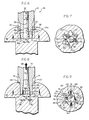
- FIGS. 6, 7, 8 and 9 An alternative embodiment of the present invention is illustrated in FIGS. 6, 7, 8 and 9.
- the alternative embodiment employs the same principals to achieve the same function as the embodiment illustrated in FIGS. 1-5 but provides an alternative embodiment of the expansion means 30.
- Elements of the alternate expansion means 30a illustrated in FIGS. 6-9 which perform like functions to parts of the expansion means 30 are designated by like reference numerals with the suffix "a".
- the bit portion 28 is formed on a free end 26 of the shank member 24.
- Expansion means 30a are selectively controllably expandable to create fastener retaining and wobble resisting forces between the outside surface 82 of the bit portion 28 and at least a portion of the inside surface 84 of the fastener 48.
- the expansion means 30a comprise an enlarged head portion 52a formed on the end of the draw shaft 34.
- the enlarged head portion 52a is a generally frustoconical member with a diameter 96 at an end distal said draw shaft 34 greater than the diameter 56 of the draw shaft 34 to which it is attached.
- the bit portion 28 is at least axially bifurcated, or split by cutting a slit 98 through the bit portion generally parallel the axes of curvature 80 of the bit portion 28.
- the slit 98 divides the bit portion 28 into a first bit portion 100 and a second bit portion 102.
- the first and second bit portions 100, 102 are generally symmetric about the slit 28.
- a gap 86 is formed between the inside surface 84 of the fastener socket 50 and the outside surface 82 of the bit portion 28. Further, as shown in FIG. 7, the slit 98 extends outwardly from the bore 32 to concave bit flutes 72 formed on the bit portion 28.
- a sloped inside bore surface 104 is formed to facilitate separation of the first and second bit portions 100, 102 when the enlarged head 52a is forced therethrough.
- the frustoconical shape of the enlarged head 52a and the sloped inside surface 104 imparts sufficient outward expansion forces on the first and second bit portions 100, 102 to force the outside surface 82 of the first and second portions 100, 102 into intimate engagement with the corresponding inside surface 84 of the fastener socket 50.
- FIG. 9 provides further details to illustrate the engagement between the expansion means 30a and the fastener socket 50. Since FIG. 9 is a view taken along the line 9-9 of FIG. 8 directed upwardly towards the drive tool, a portion of the sloped inside bore surface 104 is seen as a cresent shape on either side of the enlarged head portion 52a. The first and second bit portion 100, 102 comprising the expandable member 58a of the expansion means 30a have been forced away from each other (as indicated by arrows 106) into intimate engagement with the corresponding portions of the fastener socket 50.
- bit lobes 74 formed on opposite sides of the bit portion 28 from each other engage corresponding socket flutes 76 and at least a portion of the neighboring bit flutes 72 engage the corresponding socket lobes 78.
- the bit portion 28 of the alternative embodiment may include expansion means 30a which has been divided into three or more portions as opposed to the two portions 100, 102 comprising the expandable member 58a.
- the alternative embodiment need not be shaped only as shown in FIGS. 7 and 9, rather, the expansion means 30a may be combined with other bit portion 28 and fastener socket 50 shapes.
- the drive tool 20 is provided with engagement means 22 and a shank member 24.
- the shank member has a bore 32 formed axially therethrough and a draw shaft 34 axially movably positioned inside of the bore 32.
- the bore 32 and draw shaft 34 extend through the engagement means 22 to a camming assembly 40.
- the camming assembly includes cam pin 44 attached to the draw shaft 34 and engaged with cam grooves 46 therein. Rotation of the grip portion 38 engages the camming assembly 40 to axially move 42 the draw shaft 34 through the bore 32.
- Movement of the draw shaft 34 through the bore controllably expands and contracts the expansion means 30, 30a formed on the free end 26 of the shank member 24.
- a bit portion 28 provides driving engagement with a fastener socket 50 formed in the fastener 48.
- Upward axial movement 88 of the draw shaft 34 moves an enlarged head portion 52, 52a upwardly to forcibly expand the expansion means 30, 30a.
- the outward movement of the expansion means 30, 30a creates fastener retaining and wobble resisting forces by forcing the outside surface 82 of the bit portion 28 into intimate engagement with the inside surface 84 of the fastener socket 50.
- the camming assembly 40 provides locking means 108, of a known construction, to retain the draw shaft 34 in the upwardly drawn position to retain the fastener 48 on the drive tool 20.
- Rotational force is transferred from the drive tool 20 to the fastener 48 by engagement of the bit portion 28 with the fastener socket 50.
- the locking means 108 is disengaged thereby controllably contracting the expansion means 30, 30a to remove the fastener retaining and wobble resisting forces to permit removal of the bit portion 28 from the fastener socket 50.
Landscapes
- Engineering & Computer Science (AREA)
- Mechanical Engineering (AREA)
- Gripping On Spindles (AREA)
- Details Of Spanners, Wrenches, And Screw Drivers And Accessories (AREA)
Applications Claiming Priority (2)
| Application Number | Priority Date | Filing Date | Title |
|---|---|---|---|
| US07/526,607 US5025688A (en) | 1990-05-22 | 1990-05-22 | Expandable drive tool tip for screw retention |
| US526607 | 1990-05-22 |
Publications (2)
| Publication Number | Publication Date |
|---|---|
| EP0458447A2 true EP0458447A2 (de) | 1991-11-27 |
| EP0458447A3 EP0458447A3 (en) | 1992-07-08 |
Family
ID=24098023
Family Applications (1)
| Application Number | Title | Priority Date | Filing Date |
|---|---|---|---|
| EP19910302683 Withdrawn EP0458447A3 (en) | 1990-05-22 | 1991-03-27 | Expandable drive tool tip for screw retention |
Country Status (3)
| Country | Link |
|---|---|
| US (1) | US5025688A (de) |
| EP (1) | EP0458447A3 (de) |
| JP (1) | JPH08187675A (de) |
Cited By (2)
| Publication number | Priority date | Publication date | Assignee | Title |
|---|---|---|---|---|
| WO1997006930A1 (de) * | 1995-08-17 | 1997-02-27 | Institut Straumann Ag | Anordnung zum fassen von kleinschrauben unter verwendung eines elastisch klemmenden rings |
| DE102007004728A1 (de) * | 2007-01-31 | 2008-08-14 | Volker Biller | Schraubereinsatz (Bit) mit Schraube und verstellbarer Schraubereinsatz |
Families Citing this family (30)
| Publication number | Priority date | Publication date | Assignee | Title |
|---|---|---|---|---|
| DE19544430C1 (de) * | 1995-11-29 | 1997-05-28 | Hasco Normalien Hasenclever Co | Befestigungsmittel mit einem Stiftschlüssel und einer Schraube |
| US6286401B1 (en) | 2000-06-08 | 2001-09-11 | Mohammed Ali Hajianpour | Screwdriver with holding feature for socket head screws |
| US20050193875A1 (en) * | 2004-03-04 | 2005-09-08 | Sheriff Jackie E. | Temporary self locking drill bit |
| US7040202B2 (en) * | 2004-06-02 | 2006-05-09 | Chih-Ching Hsien | Slide stop device of a hexagonal spanner |
| US7059222B2 (en) * | 2004-06-15 | 2006-06-13 | Chih-Ching Hsien | Slide stop device of a hexagonal spanner |
| US7104168B2 (en) * | 2004-06-15 | 2006-09-12 | Chih-Ching Hsien | Slide stop device of a hexagonal spanner |
| WO2007021850A1 (en) * | 2005-08-12 | 2007-02-22 | Smith & Nephew, Inc. | Fastener retainer and driver |
| US20070122764A1 (en) * | 2005-11-28 | 2007-05-31 | Ace Surgical Supply Co., Inc. | Orthodontic bone screw |
| US7448303B2 (en) * | 2006-11-22 | 2008-11-11 | Sweat Ryan V | Pipe extraction tool |
| US20080161820A1 (en) * | 2007-01-02 | 2008-07-03 | Zimmer Technology, Inc. | Method and apparatus for locating a starting point for a surgical procedure |
| US20080190252A1 (en) * | 2007-02-08 | 2008-08-14 | Zimmer, Inc. | Global nail screw retaining screwdriver |
| US20080255573A1 (en) * | 2007-04-10 | 2008-10-16 | Zimmer, Inc. | Surgical laser trajectory instrument |
| US8156847B2 (en) * | 2007-08-07 | 2012-04-17 | Alphatec Spine, Inc. | Undercut screw feature and driver |
| DE202007012199U1 (de) * | 2007-08-31 | 2007-12-13 | Röhm Gmbh | Bohrfutter |
| DE102007054894A1 (de) * | 2007-11-15 | 2009-05-20 | Heraeus Kulzer Gmbh | Haltevorrichtung für Implantatteile |
| US9801667B2 (en) * | 2007-12-07 | 2017-10-31 | Nexus Spine, L.L.C. | Instruments, tools, and methods for presson pedicle screws |
| US20090299375A1 (en) * | 2008-06-03 | 2009-12-03 | Zimmer, Inc. | Catheter nail targeting guide |
| TW201119801A (en) * | 2009-12-08 | 2011-06-16 | New Way Tools Co Ltd | Screw remover. |
| MY166605A (en) | 2010-07-07 | 2018-07-17 | Infastech Ip Pte Ltd | Torque transmission driver |
| US8808307B2 (en) | 2010-10-13 | 2014-08-19 | Pioneer Surgical Technology, Inc. | Driver for a surgical device |
| WO2012134437A1 (en) * | 2011-03-28 | 2012-10-04 | Synthes Usa, Llc | Interlock driving instrument |
| US8777960B2 (en) | 2011-03-28 | 2014-07-15 | DePuy Synthes Products, LLC | Interlock driving instrument |
| KR101960122B1 (ko) | 2011-08-25 | 2019-03-19 | 인파스텍 인텔렉츄얼 프로퍼티즈 피티이. 엘티디. | 테이퍼진 로브형 드라이버 및 패스너 |
| US10968939B2 (en) | 2011-08-25 | 2021-04-06 | Infastech Intellectual Properties Pte. Ltd. | Tapered lobular driver and fastener |
| US20170303981A1 (en) * | 2016-04-21 | 2017-10-26 | Symmetry Medical Manufacturing, Inc. | Self-retaining screwdriver tip and mating drive feature |
| US11059162B2 (en) | 2017-05-17 | 2021-07-13 | Milwaukee Electric Tool Corporation | Screwdriver |
| EP3434417B1 (de) | 2017-07-25 | 2021-02-17 | Milwaukee Electric Tool Corporation | Antriebsführung |
| USD907452S1 (en) | 2017-07-25 | 2021-01-12 | Milwaukee Electric Tool Corporation | Drive guide |
| USD855433S1 (en) | 2017-08-09 | 2019-08-06 | Milwaukee Electric Tool Corporation | Screwdriver |
| CN117020641B (zh) * | 2023-09-22 | 2026-04-07 | 启东市东浦五金有限公司 | 一种螺丝自动组装机构 |
Family Cites Families (10)
| Publication number | Priority date | Publication date | Assignee | Title |
|---|---|---|---|---|
| US1058454A (en) * | 1912-10-19 | 1913-04-08 | Desire Fricot | Pipe-holding tool. |
| US2506922A (en) * | 1947-02-21 | 1950-05-09 | Robert S Hansen | Screw holding screw driver with expanding bit |
| US2562347A (en) * | 1949-08-12 | 1951-07-31 | Louis E Young | Screw holding screw driver |
| CH287325A (de) * | 1951-04-03 | 1952-11-30 | Kienholz Johann | Schraubenzieher. |
| US3150698A (en) * | 1960-09-08 | 1964-09-29 | H J J Company | Screw-holding screw driver |
| US3584667A (en) * | 1966-09-19 | 1971-06-15 | Textron Inc | Coupling arrangement and tools for same |
| CA1066542A (en) * | 1977-03-07 | 1979-11-20 | Bernard F. Reiland | Lobular socket head fastener with service slot |
| US4937927A (en) * | 1986-10-30 | 1990-07-03 | Slinger Manufacturing Company, Inc. | Method of joining a sleeve into a cylinder opening of a reciprocating piston |
| US4914798A (en) * | 1988-06-22 | 1990-04-10 | Gentile Charles I | Method for removing gear train assembly or final drive assembly from a power transmission casing |
| US4959917A (en) * | 1989-11-01 | 1990-10-02 | Stavros Mavrakis | Choke tube wrench for any gauge shotgun |
-
1990
- 1990-05-22 US US07/526,607 patent/US5025688A/en not_active Expired - Fee Related
-
1991
- 1991-03-27 EP EP19910302683 patent/EP0458447A3/en not_active Withdrawn
- 1991-05-21 JP JP3218127A patent/JPH08187675A/ja active Pending
Cited By (2)
| Publication number | Priority date | Publication date | Assignee | Title |
|---|---|---|---|---|
| WO1997006930A1 (de) * | 1995-08-17 | 1997-02-27 | Institut Straumann Ag | Anordnung zum fassen von kleinschrauben unter verwendung eines elastisch klemmenden rings |
| DE102007004728A1 (de) * | 2007-01-31 | 2008-08-14 | Volker Biller | Schraubereinsatz (Bit) mit Schraube und verstellbarer Schraubereinsatz |
Also Published As
| Publication number | Publication date |
|---|---|
| EP0458447A3 (en) | 1992-07-08 |
| US5025688A (en) | 1991-06-25 |
| JPH08187675A (ja) | 1996-07-23 |
Similar Documents
| Publication | Publication Date | Title |
|---|---|---|
| US5025688A (en) | Expandable drive tool tip for screw retention | |
| US5237893A (en) | Driver with fastener retention means | |
| US5019080A (en) | Drive system for prosthetic fasteners | |
| US4787278A (en) | Tool bit driver with spring retainer | |
| CA1125058A (en) | Fastener and driver assembly having a series of flutes and lobes | |
| CN112638588B (zh) | 扣件取出装置 | |
| US4970922A (en) | Torque driving tool and retainer for driven member | |
| US6152000A (en) | Driver bit and driver | |
| EP0737122B1 (de) | Gerät zum entfernen von gebrochenen schrauben mit spreitzbarer backe | |
| US4416173A (en) | Wrench adapter | |
| US5562547A (en) | Self-attachment screw | |
| US7712747B2 (en) | Retaining assembly | |
| EP1436512B1 (de) | Mit zapfen versehene gewindeeinsätze | |
| US4106178A (en) | Threaded stud driving tool | |
| US6609862B2 (en) | Tool bit | |
| EP4650108A1 (de) | Trennbarer blindlager-abzieher | |
| GB2111886A (en) | Screwdriver | |
| EP0433284B1 (de) | Einrastvorrichtung für den antrieb eines steckschrauben-schlüssels | |
| CA2275133C (en) | Screwdriver replacement bit assembly | |
| EP0322490A1 (de) | Werkzeug zum Entfernen von mit Gewinde versehenen Befestigungsmitteln | |
| IL106328A (en) | Removes broken screws with expandable forceps |
Legal Events
| Date | Code | Title | Description |
|---|---|---|---|
| PUAI | Public reference made under article 153(3) epc to a published international application that has entered the european phase |
Free format text: ORIGINAL CODE: 0009012 |
|
| AK | Designated contracting states |
Kind code of ref document: A2 Designated state(s): CH DE ES FR GB IT LI |
|
| PUAL | Search report despatched |
Free format text: ORIGINAL CODE: 0009013 |
|
| AK | Designated contracting states |
Kind code of ref document: A3 Designated state(s): CH DE ES FR GB IT LI |
|
| RAP1 | Party data changed (applicant data changed or rights of an application transferred) |
Owner name: TEXTRON INC. |
|
| 17P | Request for examination filed |
Effective date: 19921012 |
|
| STAA | Information on the status of an ep patent application or granted ep patent |
Free format text: STATUS: THE APPLICATION HAS BEEN WITHDRAWN |
|
| 18W | Application withdrawn |
Withdrawal date: 19921229 |