EP0458497A2 - Dispositif d'analyse de matériau avec carrousel - Google Patents
Dispositif d'analyse de matériau avec carrousel Download PDFInfo
- Publication number
- EP0458497A2 EP0458497A2 EP91304247A EP91304247A EP0458497A2 EP 0458497 A2 EP0458497 A2 EP 0458497A2 EP 91304247 A EP91304247 A EP 91304247A EP 91304247 A EP91304247 A EP 91304247A EP 0458497 A2 EP0458497 A2 EP 0458497A2
- Authority
- EP
- European Patent Office
- Prior art keywords
- sample
- container
- bucket
- carrousel
- radiation
- Prior art date
- Legal status (The legal status is an assumption and is not a legal conclusion. Google has not performed a legal analysis and makes no representation as to the accuracy of the status listed.)
- Granted
Links
- 239000000463 material Substances 0.000 title claims abstract description 72
- 230000005855 radiation Effects 0.000 claims abstract description 63
- 230000004913 activation Effects 0.000 claims abstract description 34
- 238000007373 indentation Methods 0.000 claims abstract description 14
- 238000003780 insertion Methods 0.000 claims abstract description 5
- 230000037431 insertion Effects 0.000 claims abstract description 5
- 230000004044 response Effects 0.000 claims abstract description 5
- 239000000523 sample Substances 0.000 claims description 88
- 239000008187 granular material Substances 0.000 description 4
- 239000012530 fluid Substances 0.000 description 2
- 239000004033 plastic Substances 0.000 description 2
- 230000008901 benefit Effects 0.000 description 1
- 230000008859 change Effects 0.000 description 1
- 239000002360 explosive Substances 0.000 description 1
- 230000005484 gravity Effects 0.000 description 1
- 238000000034 method Methods 0.000 description 1
- 230000008569 process Effects 0.000 description 1
- 230000002285 radioactive effect Effects 0.000 description 1
Images


Classifications
-
- G—PHYSICS
- G01—MEASURING; TESTING
- G01N—INVESTIGATING OR ANALYSING MATERIALS BY DETERMINING THEIR CHEMICAL OR PHYSICAL PROPERTIES
- G01N23/00—Investigating or analysing materials by the use of wave or particle radiation, e.g. X-rays or neutrons, not covered by groups G01N3/00 – G01N17/00, G01N21/00 or G01N22/00
-
- G—PHYSICS
- G01—MEASURING; TESTING
- G01N—INVESTIGATING OR ANALYSING MATERIALS BY DETERMINING THEIR CHEMICAL OR PHYSICAL PROPERTIES
- G01N23/00—Investigating or analysing materials by the use of wave or particle radiation, e.g. X-rays or neutrons, not covered by groups G01N3/00 – G01N17/00, G01N21/00 or G01N22/00
- G01N23/22—Investigating or analysing materials by the use of wave or particle radiation, e.g. X-rays or neutrons, not covered by groups G01N3/00 – G01N17/00, G01N21/00 or G01N22/00 by measuring secondary emission from the material
- G01N23/221—Investigating or analysing materials by the use of wave or particle radiation, e.g. X-rays or neutrons, not covered by groups G01N3/00 – G01N17/00, G01N21/00 or G01N22/00 by measuring secondary emission from the material by activation analysis
- G01N23/222—Investigating or analysing materials by the use of wave or particle radiation, e.g. X-rays or neutrons, not covered by groups G01N3/00 – G01N17/00, G01N21/00 or G01N22/00 by measuring secondary emission from the material by activation analysis using neutron activation analysis [NAA]
-
- G—PHYSICS
- G01—MEASURING; TESTING
- G01N—INVESTIGATING OR ANALYSING MATERIALS BY DETERMINING THEIR CHEMICAL OR PHYSICAL PROPERTIES
- G01N2223/00—Investigating materials by wave or particle radiation
- G01N2223/07—Investigating materials by wave or particle radiation secondary emission
-
- G—PHYSICS
- G01—MEASURING; TESTING
- G01N—INVESTIGATING OR ANALYSING MATERIALS BY DETERMINING THEIR CHEMICAL OR PHYSICAL PROPERTIES
- G01N2223/00—Investigating materials by wave or particle radiation
- G01N2223/07—Investigating materials by wave or particle radiation secondary emission
- G01N2223/074—Investigating materials by wave or particle radiation secondary emission activation analysis
-
- G—PHYSICS
- G01—MEASURING; TESTING
- G01N—INVESTIGATING OR ANALYSING MATERIALS BY DETERMINING THEIR CHEMICAL OR PHYSICAL PROPERTIES
- G01N2223/00—Investigating materials by wave or particle radiation
- G01N2223/30—Accessories, mechanical or electrical features
- G01N2223/309—Accessories, mechanical or electrical features support of sample holder
-
- G—PHYSICS
- G01—MEASURING; TESTING
- G01N—INVESTIGATING OR ANALYSING MATERIALS BY DETERMINING THEIR CHEMICAL OR PHYSICAL PROPERTIES
- G01N2223/00—Investigating materials by wave or particle radiation
- G01N2223/60—Specific applications or type of materials
- G01N2223/635—Specific applications or type of materials fluids, granulates
-
- G—PHYSICS
- G01—MEASURING; TESTING
- G01N—INVESTIGATING OR ANALYSING MATERIALS BY DETERMINING THEIR CHEMICAL OR PHYSICAL PROPERTIES
- G01N2223/00—Investigating materials by wave or particle radiation
- G01N2223/60—Specific applications or type of materials
- G01N2223/639—Specific applications or type of materials material in a container
Definitions
- the present invention generally pertains to material analyzers and is particularly directed to transporting material samples to an activation region of the material analyzer for analysis.
- Material analyzers are used to determine and measure the content of material samples. Prior art material analyzers are described in United States Letters Patent No. 4,582,992 to Thomas L. Atwell, James F. Miller, Ernesto Corte, Richard L. Conwell and Clinton L. Lingren and the publications cited therein.
- a material sample is positioned within an activation region located between a radiation source and a detector disposed for detecting radiation that is secondarily emitted by a material sample within the activation region when the material sample is bombarded by radiation from the radiation source.
- the detector produces signals in response to the secondarily emitted radiation; and a computer processing the signals to determine the content of the material sample.
- the radiation source and the detector are disposed within a container and are shielded by radiation shielding material within the container in order to shield the outside of the container from radiation derived from the radiation source.
- the material sample is transported into the activation region from outside the container by use of a drawer that includes a sample containment chamber.
- the drawer is slid out from the container; the material sample is placed in the sample containment chamber; and the drawer is slid into the container to position the material sample within the activation region.
- the drawer is slid out from the container and the material sample is removed from the sample containment chamber.
- the material analyzer of the present invention is an apparatus that includes a container; a radiation source disposed within the container; a detector disposed within the container for detecting radiation that is secondarily emitted by a material sample within an activation region located between the radiation source and the detector when the material sample is bombarded by radiation from the radiation source and for producing signals in response to said secondarily emitted radiation; a radiation shield within the container for shielding the outside of the container from radiation derived in the activation region from the radiation source; means for processing said signals to determine the content of the material sample; and means for transporting a material sample from outside the container to within said activation region; wherein the transporting means comprise a carrousel, disposed about an axis of rotation located between the activation region and a receiving region located outside the container, and having at least one sample containment chamber that is moved between the receiving region and the activation region when the carrousel is rotated about said axis.
- the apparatus of the present invention requires less space when being used, and thereby enables the use of the apparatus in a relatively small space such as the cargo compartment of a vehicle used to transport the material analyzer to a site where samples of the sampled material are being mined or otherwise produced.
- the carrousel may further include a second sample containment chamber located on the opposite side of the carrousel from the first mentioned containment chamber; so that as one material sample within one sample containment chamber is disposed within the activation region and being analyzed, the previous material sample is removed from the second sample containment chamber and the next material sample is placed within the second sample containment chamber, thereby significantly increasing the rate at which samples can be analyzed. Also, by providing oppositely disposed sample containment chambers in the carrousel, no significant change occurs in the center of gravity of the carrousel as the sample is transported from outside the container to within the activation region. This obviates the need to provide counterweights, as may be required when a drawer is used.
- the carrousel further includes a radiation shield disposed laterally around the sample containment chamber in order to prevent the material sample and/or the detector from being bombarded by secondarily emitted radiation from materials within the carrousel that are disposed at the sides of the sample containment chamber.
- the present invention further provides a removable bucket dimensioned for placement within the sample containment chamber.
- the bucket includes a perimetric side wall having a predominant surface area that is contoured on opposite sides of the side wall to contain exterior indentations in said predominant surface area; and a handle, including a pair of tongs shaped and disposed for insertion into the side wall indentations, and a telescopic handle joining the tongs so that the tongs can be moved toward each other to fit within the side wall indentations in order to grip the bucket and thereby enable the bucket to be transported by using the handle, and so that the tongs can be moved away from each other to enable the handle to be removed from the bucket after the bucket has been so transported.
- the present intention also provides a sample mixer.
- the sample mixer includes a Y-shaped container having a hollow leg and two hollow arms that open into the leg, wherein each arm has an extended end that is closed, and wherein the leg has an extended end that is open and dimensioned to fit precisely against a rim at an open end of the bucket; a shutter attached to the extended end of the leg for movement between open and closed positions in order to prevent sample material from flowing out of the container from the extended end of the leg when the shutter is in the closed position and for enabling sample material to flow into or from the container through the extended end of the leg when the shutter is in the open position; and an axle, with the container being disposed on the axle for rotation about an axis that is normal to the leg so that sample material within the container can be mixed by rotating the container about the axle when the shutter is in the closed position.
- Figure 1 is a perspective view of the material analyzer of the present invention with portions cut away to better show the relative placement of the carrousel, the radiation source and the detector.
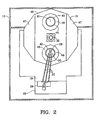
- Figure 2 is a top view of the material analyzer of Figure 1 taken along a horizontal plane immediately above the carrousel.
- Figure 3 is a side view of the material analyzer of Figure 1 taken along a vertical plane adjacent the activation region.
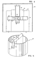
- Figure 4 is a front view of the material analyzer of Figure 1 taken along a vertical plane adjacent the activation region.
- Figure 5 is a perspective view of a sample bucket used with the material analyzer of Figure 1.
- Figure 6 is a perspective view of a sample mixer used with the bucket of Figure 5.
- the material analyzer includes a container 10, a radiation source 12, a detector 14, a carrousel 16, radiation shielding material 18 and a computer 20.
- the radiation source 12, the detector 14, the carrousel 16 and the radiation shielding material 18 are disposed at least partially within the container 10.
- the radiation source 12 includes neutron sources 12 secured to the ends of three rods 22, which are fastened to brackets 24 attached to an exterior wall of the container 10.
- the rods 22 are not radioactive.
- the brackets 24 are covered by a locked cover 26 that may be unlocked and removed when the rods 22 and the neutron sources 12 secured thereto are removed from or inserted within the container 10.
- the detector 14 is disposed above the radiation source 12.
- An activation region 28 is located between the radiation source 12 and the detector 14.
- the detector 14 is disposed for detecting radiation that is secondarily emitted by a material sample 30 within the activation region 28 when the material sample 30 is bombarded by radiation from the radiation source 12.
- the detector 14 produces signals in response to said secondarily emitted radiation; and the computer 20 processes said signals to determine the content of the material sample 30.
- the results of said processing by the computer 20 are displayed by a monitor (not shown) and printed by a printer (not shown).
- the radiation shielding material 18 is disposed within the container 10 for shielding the outside of the container 10 from radiation derived from the radiation source 12, including both direct radiation from the radiation source 12 and secondarily emitted radiation derived in the activation region 28 from the material sample 30.
- the carrousel 16 is disposed for rotation about an axle 32.
- the carrousel 16 is rotated by a motor 34 and a rubber wheel 36 mounted on the shaft of the motor 34 (as shown in Figure 3), with the motor 34 and rubber wheel 36 being located beneath the carrousel 16 so that the rubber wheel 36 continuously contacts an under surface 38 of the carrousel 16.
- the axle 32 defines an axis of rotation which is located between the activation region 28 and a receiving region 40 located outside the container 10.
- the carrousel 16 is mounted on the the axle 32 and rotated by driving the axle: or is rotated by driving the perimeter of the carrousel 16.
- the carrousel 16 includes two sample containment chambers 42, 44 located on opposite sides of the carrousel 16 such that the carrousel 16 can be rotated to position one sample containment chamber 42 within the activation region 28 and at the same time position the other sample containment chamber 44 within the receiving region 40 outside the container 10.
- the carrousel 16 also includes a radiation shield 46 disposed laterally around each sample containment chamber 42,44 in order to prevent the material sample 30 and/or the detector 14 from being bombarded by secondarily emitted radiation from materials within the carrousel 16 that are disposed at the sides of the sample containment chambers 42, 44.
- the width of the carrousel 16 is approximately four feet (1.2 m), which is considerably more than the width of a typical doorway, which is about thirty inches (75 cm). Therefore, in order to enable the carrousel 16, which is quite heavy, to be moved through a doorway without having to be severely tipped from a horizontal orientation, outside portions 47 of the carrousel 16 on two opposite sides of the carrousel 16 that do not contain the sample containment chambers 42, 44 are readily removable from a center portion 48 of the carrousel that does not exceed thirty inches in width. See Figure 2.
- the material sample 30 is placed in a bucket 49, which is placed in one of the sample containment chambers 42, 44.
- a plurality of buckets 49 are loaded with material samples 30 prior to beginning analysis of a series of samples.
- the buckets 49 are quite heavy and need to be lifted with a handle 50 to lessen the chance of the material sample 30 being spilled during handling of the bucket 49.
- Providing the buckets with handles also allows one person to carry two buckets simultaneously.
- each bucket 49 includes a perimetric side wall 52 having a predominant surface area that is contoured on opposite sides of the side wall to contain exterior indentations 54 in said predominant surface area.
- the bucket 49 is made of plastic material.
- the handle 50 includes a pair of tongs 56 that are shaped and disposed for insertion into the side wall indentations 54.
- the handle 50 includes two telescopic sections 58, 59 that join the tongs 56 so that the tongs 56 can be moved toward each other to fit within the side wall indentations 54 in order to grip the bucket 49 and thereby enable the bucket 49 to be transported by using the handle 50, and so that the tongs 56 can be moved away from each other to enable the handle 50 to be removed from the bucket 49 after the bucket has been transported and placed in one of the sample containment chambers 42, 44.
- the handle 50 must be removed because the clearance between the carrousel 16 and the shielding material 18 must be very small, such that the the carrousel 16 could not be rotated if the handle 50 remained attached to a bucket 49 placed within a sample containment chamber 42, 44.
- a sample mixer 60 is provided for use in thoroughly mixing granular material samples.
- the sample mixer 60 includes a Y-shaped container 62 having a hollow leg 64 and two hollow arms 66 that open into the leg 64. Each arm 66 has an extended end 70 that is closed.
- the leg 64 has an extended end 72 that is open and dimensioned to fit precisely against a rim 73 at the open end of the bucket 49. The open end 72 of the leg 64 thus also fits within an open end of each sample containment chamber 42, 44.
- the container 62 is made of plastic material.
- a knife blade shutter 74 is attached to the extended end 72 of the leg 64 for movement between open and closed positions. When the shutter 74 is in the open position, granular material may flow into or from the container 62 through the extended end 72 of the leg 64. When the shutter 74 is in the closed position, the shutter 74 prevent granular material from flowing out of the container 62 from the extended end 72 of the leg 64.
- the container 62 is disposed on an axle 76 for rotation about an axis that is normal to the leg 64 so that sample material within the container 62 can be thoroughly mixed by rotating the container 62 about the axle when the shutter 74 is in the closed position.
- the container After a material sample 30 is thoroughly mixed by the sample mixer 60, the container is positioned over a bucket 49, with the extended end 72 of the leg 64 fitted against the rim 73 of the bucket 49; and the shutter 74 is opened to allow the sample material 30 to flow into the bucket 49.
- the knife blade shutter 74 is closed to provide a thoroughly mixed material sample that is measured to exactly fill the bucket 49 to its rim. Excess material remains in the container 62.
- the present invention is also useful for analyzing material samples that are not fluid or granular, such as parcels or luggage.
- the apparatus of the present invention may be used at airports for analyzing luggage for explosive materials.
Landscapes
- Physics & Mathematics (AREA)
- Health & Medical Sciences (AREA)
- Life Sciences & Earth Sciences (AREA)
- Chemical & Material Sciences (AREA)
- Analytical Chemistry (AREA)
- Biochemistry (AREA)
- General Health & Medical Sciences (AREA)
- General Physics & Mathematics (AREA)
- Immunology (AREA)
- Pathology (AREA)
- Analysing Materials By The Use Of Radiation (AREA)
- Sampling And Sample Adjustment (AREA)
- Measurement Of Radiation (AREA)
- Lubricants (AREA)
- Carbon And Carbon Compounds (AREA)
- Battery Electrode And Active Subsutance (AREA)
- Organic Low-Molecular-Weight Compounds And Preparation Thereof (AREA)
- Compounds Of Unknown Constitution (AREA)
- Medicines Containing Antibodies Or Antigens For Use As Internal Diagnostic Agents (AREA)
Applications Claiming Priority (2)
| Application Number | Priority Date | Filing Date | Title |
|---|---|---|---|
| US527483 | 1990-05-23 | ||
| US07/527,483 US5053185A (en) | 1990-05-23 | 1990-05-23 | Material analyzer with carousel |
Publications (3)
| Publication Number | Publication Date |
|---|---|
| EP0458497A2 true EP0458497A2 (fr) | 1991-11-27 |
| EP0458497A3 EP0458497A3 (en) | 1992-01-08 |
| EP0458497B1 EP0458497B1 (fr) | 1995-03-08 |
Family
ID=24101639
Family Applications (1)
| Application Number | Title | Priority Date | Filing Date |
|---|---|---|---|
| EP91304247A Expired - Lifetime EP0458497B1 (fr) | 1990-05-23 | 1991-05-10 | Dispositif d'analyse de matériau avec carrousel |
Country Status (11)
| Country | Link |
|---|---|
| US (1) | US5053185A (fr) |
| EP (1) | EP0458497B1 (fr) |
| JP (1) | JP2648405B2 (fr) |
| KR (1) | KR0170782B1 (fr) |
| AT (1) | ATE119669T1 (fr) |
| AU (1) | AU642015B2 (fr) |
| BR (1) | BR9102076A (fr) |
| CA (1) | CA2041966A1 (fr) |
| DE (1) | DE69107893T2 (fr) |
| FI (1) | FI100364B (fr) |
| MX (1) | MX169418B (fr) |
Cited By (1)
| Publication number | Priority date | Publication date | Assignee | Title |
|---|---|---|---|---|
| DE10163846C5 (de) * | 2001-12-22 | 2013-01-24 | Yxlon International X-Ray Gmbh | Vorrichtung zur Handhabung und Durchleuchtung von Leichtmetall-Rädern in Röntgen-Prüfanlage |
Families Citing this family (9)
| Publication number | Priority date | Publication date | Assignee | Title |
|---|---|---|---|---|
| AU766378B2 (en) | 1999-05-27 | 2003-10-16 | Analyser Systems Sa | Method and apparatus for multi-parameter digital pulse pile-up rejection |
| US7304750B2 (en) * | 1999-12-17 | 2007-12-04 | Nektar Therapeutics | Systems and methods for non-destructive mass sensing |
| US6922455B2 (en) * | 2002-01-28 | 2005-07-26 | Starfire Industries Management, Inc. | Gas-target neutron generation and applications |
| US7152002B2 (en) * | 2002-06-03 | 2006-12-19 | Sabia, Inc. | Method and apparatus for analysis of elements in bulk substance |
| US8555785B2 (en) * | 2009-02-02 | 2013-10-15 | Ra Brands, L.L.C. | Shotshell wad with shot confinement feature |
| CN105738406B (zh) * | 2016-01-31 | 2018-08-10 | 安徽泷汇安全科技有限公司 | 一种针对液体的安全检测方法 |
| CN110849684B (zh) * | 2019-11-19 | 2022-04-01 | 中国核动力研究设计院 | 一种用于制备放射性样品的装置 |
| CN115267882B (zh) * | 2021-04-29 | 2024-12-13 | 核工业西南物理研究院 | 聚变反应堆辐照样品进样器 |
| CN119805539B (zh) * | 2025-03-10 | 2025-05-09 | 山西环美环境科技有限公司 | 一种γ辐射检测装置及检测方法 |
Family Cites Families (13)
| Publication number | Priority date | Publication date | Assignee | Title |
|---|---|---|---|---|
| US2514126A (en) * | 1949-12-08 | 1950-07-04 | Patterson Kelley Co | Blending or mixing apparatus |
| FR1491260A (fr) * | 1966-04-15 | 1967-08-11 | Atome Ind S A L | Procédé semi-continu d'analyse par activation et dispositif de mise en oeuvre dudit procédé ou d'un procédé similaire |
| US3796873A (en) | 1971-05-03 | 1974-03-12 | Colgate Palmolive Co | Container fill weight control using nuclear radiation |
| US3923191A (en) * | 1974-09-11 | 1975-12-02 | Fluoroware Inc | Wafer basket and handle |
| US4117935A (en) * | 1976-06-09 | 1978-10-03 | Bedford Engineering Corp. | Apparatus for and method of measuring product mass |
| US4147618A (en) * | 1977-03-14 | 1979-04-03 | Bedford Engineering Corporation | Method and apparatus for measuring product contents |
| DE2917723A1 (de) * | 1979-05-02 | 1980-11-13 | N Proizv Ob Geofizika | Verfahren zur analyse der zusammensetzung von substanzproben durch radioisotope und einrichtung zur durchfuehrung dieses verfahrens |
| US4283148A (en) * | 1979-07-12 | 1981-08-11 | Aluminum Company Of America | Apparatus and method for solid particle bulk density measurements |
| DE3119464A1 (de) * | 1981-05-15 | 1982-12-09 | Weisser Spulenkörper GmbH & Co KG, 7086 Neresheim | Tragbuegel fuer behaelter |
| US4459258A (en) * | 1981-08-20 | 1984-07-10 | General Electric Company | Elemental analyzer and method |
| US4496070A (en) * | 1982-09-29 | 1985-01-29 | Lane Jr Samuel H | Container and lid forming a disposable mold |
| US4582992A (en) * | 1984-08-10 | 1986-04-15 | Gamma-Metrics | Self-contained, on-line, real-time bulk material analyzer |
| JPS61240145A (ja) * | 1985-04-17 | 1986-10-25 | Hitachi Medical Corp | 産業用x線ct装置 |
-
1990
- 1990-05-23 US US07/527,483 patent/US5053185A/en not_active Expired - Lifetime
-
1991
- 1991-05-07 CA CA002041966A patent/CA2041966A1/fr not_active Abandoned
- 1991-05-08 FI FI912232A patent/FI100364B/fi active
- 1991-05-10 AT AT91304247T patent/ATE119669T1/de not_active IP Right Cessation
- 1991-05-10 EP EP91304247A patent/EP0458497B1/fr not_active Expired - Lifetime
- 1991-05-10 DE DE69107893T patent/DE69107893T2/de not_active Expired - Fee Related
- 1991-05-14 AU AU77003/91A patent/AU642015B2/en not_active Ceased
- 1991-05-20 KR KR1019910008145A patent/KR0170782B1/ko not_active Expired - Fee Related
- 1991-05-21 BR BR919102076A patent/BR9102076A/pt not_active IP Right Cessation
- 1991-05-22 MX MX025887A patent/MX169418B/es unknown
- 1991-05-22 JP JP3146950A patent/JP2648405B2/ja not_active Expired - Lifetime
Cited By (1)
| Publication number | Priority date | Publication date | Assignee | Title |
|---|---|---|---|---|
| DE10163846C5 (de) * | 2001-12-22 | 2013-01-24 | Yxlon International X-Ray Gmbh | Vorrichtung zur Handhabung und Durchleuchtung von Leichtmetall-Rädern in Röntgen-Prüfanlage |
Also Published As
| Publication number | Publication date |
|---|---|
| JPH0540078A (ja) | 1993-02-19 |
| US5053185A (en) | 1991-10-01 |
| KR910020430A (ko) | 1991-12-20 |
| EP0458497B1 (fr) | 1995-03-08 |
| FI100364B (fi) | 1997-11-14 |
| FI912232A7 (fi) | 1991-11-24 |
| DE69107893D1 (de) | 1995-04-13 |
| EP0458497A3 (en) | 1992-01-08 |
| AU642015B2 (en) | 1993-10-07 |
| KR0170782B1 (ko) | 1999-05-01 |
| JP2648405B2 (ja) | 1997-08-27 |
| MX169418B (es) | 1993-07-02 |
| ATE119669T1 (de) | 1995-03-15 |
| DE69107893T2 (de) | 1995-07-20 |
| AU7700391A (en) | 1991-11-28 |
| BR9102076A (pt) | 1991-12-24 |
| FI912232A0 (fi) | 1991-05-08 |
| CA2041966A1 (fr) | 1991-11-24 |
Similar Documents
| Publication | Publication Date | Title |
|---|---|---|
| EP0458497B1 (fr) | Dispositif d'analyse de matériau avec carrousel | |
| CA1166038A (fr) | Dispositif d'amenee d'echantillons | |
| CA1184785A (fr) | Echantillonneuse | |
| KR101892569B1 (ko) | 핵종분석용 이동형 방사선 차폐장치 | |
| US20100278312A1 (en) | Core measurements stand for use with a portable xrf analyzer | |
| US20040156477A1 (en) | Radiation scanning of cargo conveyances at seaports and the like | |
| US3942003A (en) | Method and apparatus for the in situ analysis of marine ore concretions | |
| DE2727989C3 (de) | Einrichtung zur Bestimmung von Uran und/oder Thorium in Erzproben | |
| EP1145043A1 (fr) | Dispositif et procedes de recherche de sources radioactives dans un echantillon | |
| EP0606121B1 (fr) | Appareil automatique d'inspection d'un produit en poudre | |
| EP0178069A2 (fr) | Procédé et dispositif pour la détection de la radioactivité dans un conteneur | |
| DE69406657T2 (de) | Abgedichteter Behälter, und Zusammenfügung dieses Behälters und einer angepassten Halterung | |
| JP7061300B1 (ja) | 粉体状の廃棄物の放射性物質による汚染の検査方法 | |
| US5670717A (en) | Method and device for detecting and/or measuring at least one geophysical parameter from a core sample | |
| Corey et al. | Determination of density and water content of marine sediment in an unextruded core using fast neutron and gamma ray attenuation | |
| JPH076976B2 (ja) | 金属粒子組成分析用装置 | |
| EP0410130B1 (fr) | Procédé et dispositif pour la détermination de l'enrichissement de poudre de dioxide d'uranium | |
| EP0398856A3 (fr) | Appareil pourvu d'une tête de mesure | |
| KR102679331B1 (ko) | 방사성 금속폐기물의 오염도 측정 및 분류설비의 방사성 오염 위치 판별 검증용 방사선원 드럼장치 | |
| RU2045046C1 (ru) | Устройство для нейтронно-активационного анализа | |
| DE2051854C3 (de) | Einrichtung zum Transport von Proben ijnd Flußmonitoren | |
| SU1089492A1 (ru) | Пробоподающее устройство рентгенорадиометрического анализатора порошковых проб | |
| KR20040043986A (ko) | 다목적 Cf-252 중성자 선원 취급장치 | |
| Jeandey et al. | Comparative imaging of liquids in rocks by NMR and differential X-ray CT[computer tomography] | |
| CS260685B1 (cs) | Zařízení pro analýzu látek metodou nepružného rozptylu neutronů |
Legal Events
| Date | Code | Title | Description |
|---|---|---|---|
| PUAI | Public reference made under article 153(3) epc to a published international application that has entered the european phase |
Free format text: ORIGINAL CODE: 0009012 |
|
| PUAL | Search report despatched |
Free format text: ORIGINAL CODE: 0009013 |
|
| AK | Designated contracting states |
Kind code of ref document: A2 Designated state(s): AT BE CH DE DK ES FR GB GR IT LI LU NL SE |
|
| AK | Designated contracting states |
Kind code of ref document: A3 Designated state(s): AT BE CH DE DK ES FR GB GR IT LI LU NL SE |
|
| 17P | Request for examination filed |
Effective date: 19920615 |
|
| 17Q | First examination report despatched |
Effective date: 19931029 |
|
| GRAA | (expected) grant |
Free format text: ORIGINAL CODE: 0009210 |
|
| AK | Designated contracting states |
Kind code of ref document: B1 Designated state(s): AT BE CH DE DK ES FR GB GR IT LI LU NL SE |
|
| PG25 | Lapsed in a contracting state [announced via postgrant information from national office to epo] |
Ref country code: IT Free format text: LAPSE BECAUSE OF FAILURE TO SUBMIT A TRANSLATION OF THE DESCRIPTION OR TO PAY THE FEE WITHIN THE PRE;WARNING: LAPSES OF ITALIAN PATENTS WITH EFFECTIVE DATE BEFORE 2007 MAY HAVE OCCURRED AT ANY TIME BEFORE 2007. THE CORRECT EFFECTIVE DATE MAY BE DIFFERENT FROM THE ONE RECORDED.SCRIBED TIME-LIMIT Effective date: 19950308 Ref country code: CH Effective date: 19950308 Ref country code: NL Free format text: LAPSE BECAUSE OF NON-PAYMENT OF DUE FEES Effective date: 19950308 Ref country code: GR Free format text: LAPSE BECAUSE OF FAILURE TO SUBMIT A TRANSLATION OF THE DESCRIPTION OR TO PAY THE FEE WITHIN THE PRESCRIBED TIME-LIMIT Effective date: 19950308 Ref country code: BE Effective date: 19950308 Ref country code: AT Effective date: 19950308 Ref country code: ES Free format text: THE PATENT HAS BEEN ANNULLED BY A DECISION OF A NATIONAL AUTHORITY Effective date: 19950308 Ref country code: LI Effective date: 19950308 Ref country code: DK Effective date: 19950308 |
|
| REF | Corresponds to: |
Ref document number: 119669 Country of ref document: AT Date of ref document: 19950315 Kind code of ref document: T |
|
| ET | Fr: translation filed | ||
| REF | Corresponds to: |
Ref document number: 69107893 Country of ref document: DE Date of ref document: 19950413 |
|
| PG25 | Lapsed in a contracting state [announced via postgrant information from national office to epo] |
Ref country code: LU Free format text: LAPSE BECAUSE OF NON-PAYMENT OF DUE FEES Effective date: 19950531 |
|
| PG25 | Lapsed in a contracting state [announced via postgrant information from national office to epo] |
Ref country code: SE Effective date: 19950608 |
|
| REG | Reference to a national code |
Ref country code: CH Ref legal event code: PL |
|
| NLV1 | Nl: lapsed or annulled due to failure to fulfill the requirements of art. 29p and 29m of the patents act | ||
| PLBE | No opposition filed within time limit |
Free format text: ORIGINAL CODE: 0009261 |
|
| STAA | Information on the status of an ep patent application or granted ep patent |
Free format text: STATUS: NO OPPOSITION FILED WITHIN TIME LIMIT |
|
| 26N | No opposition filed | ||
| PGFP | Annual fee paid to national office [announced via postgrant information from national office to epo] |
Ref country code: GB Payment date: 20000502 Year of fee payment: 10 |
|
| PGFP | Annual fee paid to national office [announced via postgrant information from national office to epo] |
Ref country code: DE Payment date: 20000524 Year of fee payment: 10 |
|
| PGFP | Annual fee paid to national office [announced via postgrant information from national office to epo] |
Ref country code: FR Payment date: 20000530 Year of fee payment: 10 |
|
| PG25 | Lapsed in a contracting state [announced via postgrant information from national office to epo] |
Ref country code: GB Free format text: LAPSE BECAUSE OF NON-PAYMENT OF DUE FEES Effective date: 20010510 |
|
| GBPC | Gb: european patent ceased through non-payment of renewal fee |
Effective date: 20010510 |
|
| PG25 | Lapsed in a contracting state [announced via postgrant information from national office to epo] |
Ref country code: FR Free format text: LAPSE BECAUSE OF NON-PAYMENT OF DUE FEES Effective date: 20020131 |
|
| PG25 | Lapsed in a contracting state [announced via postgrant information from national office to epo] |
Ref country code: DE Free format text: LAPSE BECAUSE OF NON-PAYMENT OF DUE FEES Effective date: 20020301 |