EP0458666A1 - Procédé de fabrication d'une structure creuse utilisable notamment pour le stockage de fluides sous pression - Google Patents
Procédé de fabrication d'une structure creuse utilisable notamment pour le stockage de fluides sous pression Download PDFInfo
- Publication number
- EP0458666A1 EP0458666A1 EP91401030A EP91401030A EP0458666A1 EP 0458666 A1 EP0458666 A1 EP 0458666A1 EP 91401030 A EP91401030 A EP 91401030A EP 91401030 A EP91401030 A EP 91401030A EP 0458666 A1 EP0458666 A1 EP 0458666A1
- Authority
- EP
- European Patent Office
- Prior art keywords
- tube
- resin
- winding
- composition
- hollow
- Prior art date
- Legal status (The legal status is an assumption and is not a legal conclusion. Google has not performed a legal analysis and makes no representation as to the accuracy of the status listed.)
- Granted
Links
- 238000003860 storage Methods 0.000 title claims description 14
- 239000012530 fluid Substances 0.000 title claims description 9
- 238000004519 manufacturing process Methods 0.000 title claims description 6
- 239000000203 mixture Substances 0.000 claims abstract description 25
- 238000000034 method Methods 0.000 claims abstract description 21
- 238000004891 communication Methods 0.000 claims abstract description 7
- 229920005989 resin Polymers 0.000 claims description 24
- 239000011347 resin Substances 0.000 claims description 24
- 238000004804 winding Methods 0.000 claims description 16
- 239000000463 material Substances 0.000 claims description 9
- 239000000835 fiber Substances 0.000 claims description 7
- 238000010438 heat treatment Methods 0.000 claims description 6
- 238000004132 cross linking Methods 0.000 claims description 4
- 230000015572 biosynthetic process Effects 0.000 claims description 3
- 238000005470 impregnation Methods 0.000 claims description 3
- 238000007789 sealing Methods 0.000 claims description 3
- 229920001187 thermosetting polymer Polymers 0.000 claims description 3
- 238000009954 braiding Methods 0.000 abstract description 2
- 238000005452 bending Methods 0.000 abstract 1
- 238000007493 shaping process Methods 0.000 abstract 1
- 239000010410 layer Substances 0.000 description 9
- 239000007789 gas Substances 0.000 description 6
- IJGRMHOSHXDMSA-UHFFFAOYSA-N Atomic nitrogen Chemical compound N#N IJGRMHOSHXDMSA-UHFFFAOYSA-N 0.000 description 4
- 239000004698 Polyethylene Substances 0.000 description 4
- 229920001971 elastomer Polymers 0.000 description 4
- -1 polyethylene Polymers 0.000 description 4
- 229920000573 polyethylene Polymers 0.000 description 4
- 239000004593 Epoxy Substances 0.000 description 3
- 229910000831 Steel Inorganic materials 0.000 description 3
- 239000004760 aramid Substances 0.000 description 3
- 229920003235 aromatic polyamide Polymers 0.000 description 3
- 239000003365 glass fiber Substances 0.000 description 3
- 239000002184 metal Substances 0.000 description 3
- 229920001568 phenolic resin Polymers 0.000 description 3
- 239000005011 phenolic resin Substances 0.000 description 3
- 230000002787 reinforcement Effects 0.000 description 3
- 230000003014 reinforcing effect Effects 0.000 description 3
- 239000010959 steel Substances 0.000 description 3
- XLYOFNOQVPJJNP-UHFFFAOYSA-N water Substances O XLYOFNOQVPJJNP-UHFFFAOYSA-N 0.000 description 3
- 239000002033 PVDF binder Substances 0.000 description 2
- 239000000806 elastomer Substances 0.000 description 2
- 239000003822 epoxy resin Substances 0.000 description 2
- 229910052757 nitrogen Inorganic materials 0.000 description 2
- 229920000647 polyepoxide Polymers 0.000 description 2
- 229920002981 polyvinylidene fluoride Polymers 0.000 description 2
- 239000012783 reinforcing fiber Substances 0.000 description 2
- 230000029058 respiratory gaseous exchange Effects 0.000 description 2
- 239000005060 rubber Substances 0.000 description 2
- 238000012360 testing method Methods 0.000 description 2
- 229920001169 thermoplastic Polymers 0.000 description 2
- 239000004416 thermosoftening plastic Substances 0.000 description 2
- 238000012546 transfer Methods 0.000 description 2
- KXGFMDJXCMQABM-UHFFFAOYSA-N 2-methoxy-6-methylphenol Chemical compound [CH]OC1=CC=CC([CH])=C1O KXGFMDJXCMQABM-UHFFFAOYSA-N 0.000 description 1
- LCFVJGUPQDGYKZ-UHFFFAOYSA-N Bisphenol A diglycidyl ether Chemical compound C=1C=C(OCC2OC2)C=CC=1C(C)(C)C(C=C1)=CC=C1OCC1CO1 LCFVJGUPQDGYKZ-UHFFFAOYSA-N 0.000 description 1
- 229920000049 Carbon (fiber) Polymers 0.000 description 1
- 229920002943 EPDM rubber Polymers 0.000 description 1
- 229920000877 Melamine resin Polymers 0.000 description 1
- 229920000459 Nitrile rubber Polymers 0.000 description 1
- 239000004952 Polyamide Substances 0.000 description 1
- 229920000297 Rayon Polymers 0.000 description 1
- 241001417494 Sciaenidae Species 0.000 description 1
- 229920001807 Urea-formaldehyde Polymers 0.000 description 1
- GZCGUPFRVQAUEE-SLPGGIOYSA-N aldehydo-D-glucose Chemical compound OC[C@@H](O)[C@@H](O)[C@H](O)[C@@H](O)C=O GZCGUPFRVQAUEE-SLPGGIOYSA-N 0.000 description 1
- 229920000180 alkyd Polymers 0.000 description 1
- 150000008064 anhydrides Chemical class 0.000 description 1
- 230000000712 assembly Effects 0.000 description 1
- 238000000429 assembly Methods 0.000 description 1
- 238000012550 audit Methods 0.000 description 1
- 230000009172 bursting Effects 0.000 description 1
- 239000004917 carbon fiber Substances 0.000 description 1
- 239000002131 composite material Substances 0.000 description 1
- 238000010411 cooking Methods 0.000 description 1
- 238000001816 cooling Methods 0.000 description 1
- 238000013461 design Methods 0.000 description 1
- 230000001627 detrimental effect Effects 0.000 description 1
- XXBDWLFCJWSEKW-UHFFFAOYSA-N dimethylbenzylamine Chemical compound CN(C)CC1=CC=CC=C1 XXBDWLFCJWSEKW-UHFFFAOYSA-N 0.000 description 1
- 238000001035 drying Methods 0.000 description 1
- 230000000694 effects Effects 0.000 description 1
- 239000013536 elastomeric material Substances 0.000 description 1
- 239000006260 foam Substances 0.000 description 1
- 238000005187 foaming Methods 0.000 description 1
- 235000021189 garnishes Nutrition 0.000 description 1
- 239000011521 glass Substances 0.000 description 1
- 238000009434 installation Methods 0.000 description 1
- 239000004816 latex Substances 0.000 description 1
- 229920000126 latex Polymers 0.000 description 1
- 238000002844 melting Methods 0.000 description 1
- 230000008018 melting Effects 0.000 description 1
- 238000012986 modification Methods 0.000 description 1
- 230000004048 modification Effects 0.000 description 1
- 238000013021 overheating Methods 0.000 description 1
- 230000000737 periodic effect Effects 0.000 description 1
- 239000004033 plastic Substances 0.000 description 1
- 229920003023 plastic Polymers 0.000 description 1
- 229920002647 polyamide Polymers 0.000 description 1
- 229920000728 polyester Polymers 0.000 description 1
- 239000004848 polyfunctional curative Substances 0.000 description 1
- 239000000843 powder Substances 0.000 description 1
- 230000001681 protective effect Effects 0.000 description 1
- 239000011241 protective layer Substances 0.000 description 1
- 239000002964 rayon Substances 0.000 description 1
- 230000006641 stabilisation Effects 0.000 description 1
- 238000011105 stabilization Methods 0.000 description 1
- 230000000087 stabilizing effect Effects 0.000 description 1
- 229910001220 stainless steel Inorganic materials 0.000 description 1
- 239000010935 stainless steel Substances 0.000 description 1
- 239000003351 stiffener Substances 0.000 description 1
- 230000008961 swelling Effects 0.000 description 1
- 229920005992 thermoplastic resin Polymers 0.000 description 1
- 229920001567 vinyl ester resin Polymers 0.000 description 1
- 238000004073 vulcanization Methods 0.000 description 1
- 239000004636 vulcanized rubber Substances 0.000 description 1
Images

Classifications
-
- F—MECHANICAL ENGINEERING; LIGHTING; HEATING; WEAPONS; BLASTING
- F16—ENGINEERING ELEMENTS AND UNITS; GENERAL MEASURES FOR PRODUCING AND MAINTAINING EFFECTIVE FUNCTIONING OF MACHINES OR INSTALLATIONS; THERMAL INSULATION IN GENERAL
- F16J—PISTONS; CYLINDERS; SEALINGS
- F16J12/00—Pressure vessels in general
-
- F—MECHANICAL ENGINEERING; LIGHTING; HEATING; WEAPONS; BLASTING
- F16—ENGINEERING ELEMENTS AND UNITS; GENERAL MEASURES FOR PRODUCING AND MAINTAINING EFFECTIVE FUNCTIONING OF MACHINES OR INSTALLATIONS; THERMAL INSULATION IN GENERAL
- F16L—PIPES; JOINTS OR FITTINGS FOR PIPES; SUPPORTS FOR PIPES, CABLES OR PROTECTIVE TUBING; MEANS FOR THERMAL INSULATION IN GENERAL
- F16L11/00—Hoses, i.e. flexible pipes
- F16L11/04—Hoses, i.e. flexible pipes made of rubber or flexible plastics
- F16L11/11—Hoses, i.e. flexible pipes made of rubber or flexible plastics with corrugated wall
- F16L11/115—Hoses, i.e. flexible pipes made of rubber or flexible plastics with corrugated wall having reinforcements not embedded in the wall
-
- F—MECHANICAL ENGINEERING; LIGHTING; HEATING; WEAPONS; BLASTING
- F17—STORING OR DISTRIBUTING GASES OR LIQUIDS
- F17C—VESSELS FOR CONTAINING OR STORING COMPRESSED, LIQUEFIED OR SOLIDIFIED GASES; FIXED-CAPACITY GAS-HOLDERS; FILLING VESSELS WITH, OR DISCHARGING FROM VESSELS, COMPRESSED, LIQUEFIED, OR SOLIDIFIED GASES
- F17C1/00—Pressure vessels, e.g. gas cylinder, gas tank, replaceable cartridge
- F17C1/02—Pressure vessels, e.g. gas cylinder, gas tank, replaceable cartridge involving reinforcing arrangements
- F17C1/04—Protecting sheathings
- F17C1/06—Protecting sheathings built-up from wound-on bands or filamentary material, e.g. wires
-
- F—MECHANICAL ENGINEERING; LIGHTING; HEATING; WEAPONS; BLASTING
- F17—STORING OR DISTRIBUTING GASES OR LIQUIDS
- F17C—VESSELS FOR CONTAINING OR STORING COMPRESSED, LIQUEFIED OR SOLIDIFIED GASES; FIXED-CAPACITY GAS-HOLDERS; FILLING VESSELS WITH, OR DISCHARGING FROM VESSELS, COMPRESSED, LIQUEFIED, OR SOLIDIFIED GASES
- F17C2201/00—Vessel construction, in particular geometry, arrangement or size
- F17C2201/01—Shape
- F17C2201/0138—Shape tubular
-
- F—MECHANICAL ENGINEERING; LIGHTING; HEATING; WEAPONS; BLASTING
- F17—STORING OR DISTRIBUTING GASES OR LIQUIDS
- F17C—VESSELS FOR CONTAINING OR STORING COMPRESSED, LIQUEFIED OR SOLIDIFIED GASES; FIXED-CAPACITY GAS-HOLDERS; FILLING VESSELS WITH, OR DISCHARGING FROM VESSELS, COMPRESSED, LIQUEFIED, OR SOLIDIFIED GASES
- F17C2201/00—Vessel construction, in particular geometry, arrangement or size
- F17C2201/05—Size
- F17C2201/054—Size medium (>1 m3)
-
- F—MECHANICAL ENGINEERING; LIGHTING; HEATING; WEAPONS; BLASTING
- F17—STORING OR DISTRIBUTING GASES OR LIQUIDS
- F17C—VESSELS FOR CONTAINING OR STORING COMPRESSED, LIQUEFIED OR SOLIDIFIED GASES; FIXED-CAPACITY GAS-HOLDERS; FILLING VESSELS WITH, OR DISCHARGING FROM VESSELS, COMPRESSED, LIQUEFIED, OR SOLIDIFIED GASES
- F17C2201/00—Vessel construction, in particular geometry, arrangement or size
- F17C2201/05—Size
- F17C2201/056—Small (<1 m3)
-
- F—MECHANICAL ENGINEERING; LIGHTING; HEATING; WEAPONS; BLASTING
- F17—STORING OR DISTRIBUTING GASES OR LIQUIDS
- F17C—VESSELS FOR CONTAINING OR STORING COMPRESSED, LIQUEFIED OR SOLIDIFIED GASES; FIXED-CAPACITY GAS-HOLDERS; FILLING VESSELS WITH, OR DISCHARGING FROM VESSELS, COMPRESSED, LIQUEFIED, OR SOLIDIFIED GASES
- F17C2203/00—Vessel construction, in particular walls or details thereof
- F17C2203/01—Reinforcing or suspension means
- F17C2203/011—Reinforcing means
- F17C2203/012—Reinforcing means on or in the wall, e.g. ribs
-
- F—MECHANICAL ENGINEERING; LIGHTING; HEATING; WEAPONS; BLASTING
- F17—STORING OR DISTRIBUTING GASES OR LIQUIDS
- F17C—VESSELS FOR CONTAINING OR STORING COMPRESSED, LIQUEFIED OR SOLIDIFIED GASES; FIXED-CAPACITY GAS-HOLDERS; FILLING VESSELS WITH, OR DISCHARGING FROM VESSELS, COMPRESSED, LIQUEFIED, OR SOLIDIFIED GASES
- F17C2203/00—Vessel construction, in particular walls or details thereof
- F17C2203/01—Reinforcing or suspension means
- F17C2203/011—Reinforcing means
- F17C2203/013—Reinforcing means in the vessel, e.g. columns
-
- F—MECHANICAL ENGINEERING; LIGHTING; HEATING; WEAPONS; BLASTING
- F17—STORING OR DISTRIBUTING GASES OR LIQUIDS
- F17C—VESSELS FOR CONTAINING OR STORING COMPRESSED, LIQUEFIED OR SOLIDIFIED GASES; FIXED-CAPACITY GAS-HOLDERS; FILLING VESSELS WITH, OR DISCHARGING FROM VESSELS, COMPRESSED, LIQUEFIED, OR SOLIDIFIED GASES
- F17C2203/00—Vessel construction, in particular walls or details thereof
- F17C2203/03—Thermal insulations
- F17C2203/0304—Thermal insulations by solid means
- F17C2203/0329—Foam
-
- F—MECHANICAL ENGINEERING; LIGHTING; HEATING; WEAPONS; BLASTING
- F17—STORING OR DISTRIBUTING GASES OR LIQUIDS
- F17C—VESSELS FOR CONTAINING OR STORING COMPRESSED, LIQUEFIED OR SOLIDIFIED GASES; FIXED-CAPACITY GAS-HOLDERS; FILLING VESSELS WITH, OR DISCHARGING FROM VESSELS, COMPRESSED, LIQUEFIED, OR SOLIDIFIED GASES
- F17C2203/00—Vessel construction, in particular walls or details thereof
- F17C2203/06—Materials for walls or layers thereof; Properties or structures of walls or their materials
- F17C2203/0602—Wall structures; Special features thereof
- F17C2203/0607—Coatings
-
- F—MECHANICAL ENGINEERING; LIGHTING; HEATING; WEAPONS; BLASTING
- F17—STORING OR DISTRIBUTING GASES OR LIQUIDS
- F17C—VESSELS FOR CONTAINING OR STORING COMPRESSED, LIQUEFIED OR SOLIDIFIED GASES; FIXED-CAPACITY GAS-HOLDERS; FILLING VESSELS WITH, OR DISCHARGING FROM VESSELS, COMPRESSED, LIQUEFIED, OR SOLIDIFIED GASES
- F17C2203/00—Vessel construction, in particular walls or details thereof
- F17C2203/06—Materials for walls or layers thereof; Properties or structures of walls or their materials
- F17C2203/0602—Wall structures; Special features thereof
- F17C2203/0612—Wall structures
- F17C2203/0614—Single wall
- F17C2203/0617—Single wall with one layer
-
- F—MECHANICAL ENGINEERING; LIGHTING; HEATING; WEAPONS; BLASTING
- F17—STORING OR DISTRIBUTING GASES OR LIQUIDS
- F17C—VESSELS FOR CONTAINING OR STORING COMPRESSED, LIQUEFIED OR SOLIDIFIED GASES; FIXED-CAPACITY GAS-HOLDERS; FILLING VESSELS WITH, OR DISCHARGING FROM VESSELS, COMPRESSED, LIQUEFIED, OR SOLIDIFIED GASES
- F17C2203/00—Vessel construction, in particular walls or details thereof
- F17C2203/06—Materials for walls or layers thereof; Properties or structures of walls or their materials
- F17C2203/0602—Wall structures; Special features thereof
- F17C2203/0612—Wall structures
- F17C2203/0614—Single wall
- F17C2203/0619—Single wall with two layers
-
- F—MECHANICAL ENGINEERING; LIGHTING; HEATING; WEAPONS; BLASTING
- F17—STORING OR DISTRIBUTING GASES OR LIQUIDS
- F17C—VESSELS FOR CONTAINING OR STORING COMPRESSED, LIQUEFIED OR SOLIDIFIED GASES; FIXED-CAPACITY GAS-HOLDERS; FILLING VESSELS WITH, OR DISCHARGING FROM VESSELS, COMPRESSED, LIQUEFIED, OR SOLIDIFIED GASES
- F17C2203/00—Vessel construction, in particular walls or details thereof
- F17C2203/06—Materials for walls or layers thereof; Properties or structures of walls or their materials
- F17C2203/0602—Wall structures; Special features thereof
- F17C2203/0612—Wall structures
- F17C2203/0614—Single wall
- F17C2203/0621—Single wall with three layers
-
- F—MECHANICAL ENGINEERING; LIGHTING; HEATING; WEAPONS; BLASTING
- F17—STORING OR DISTRIBUTING GASES OR LIQUIDS
- F17C—VESSELS FOR CONTAINING OR STORING COMPRESSED, LIQUEFIED OR SOLIDIFIED GASES; FIXED-CAPACITY GAS-HOLDERS; FILLING VESSELS WITH, OR DISCHARGING FROM VESSELS, COMPRESSED, LIQUEFIED, OR SOLIDIFIED GASES
- F17C2203/00—Vessel construction, in particular walls or details thereof
- F17C2203/06—Materials for walls or layers thereof; Properties or structures of walls or their materials
- F17C2203/0634—Materials for walls or layers thereof
- F17C2203/0636—Metals
- F17C2203/0639—Steels
- F17C2203/0643—Stainless steels
-
- F—MECHANICAL ENGINEERING; LIGHTING; HEATING; WEAPONS; BLASTING
- F17—STORING OR DISTRIBUTING GASES OR LIQUIDS
- F17C—VESSELS FOR CONTAINING OR STORING COMPRESSED, LIQUEFIED OR SOLIDIFIED GASES; FIXED-CAPACITY GAS-HOLDERS; FILLING VESSELS WITH, OR DISCHARGING FROM VESSELS, COMPRESSED, LIQUEFIED, OR SOLIDIFIED GASES
- F17C2203/00—Vessel construction, in particular walls or details thereof
- F17C2203/06—Materials for walls or layers thereof; Properties or structures of walls or their materials
- F17C2203/0634—Materials for walls or layers thereof
- F17C2203/0636—Metals
- F17C2203/0656—Metals in form of filaments
-
- F—MECHANICAL ENGINEERING; LIGHTING; HEATING; WEAPONS; BLASTING
- F17—STORING OR DISTRIBUTING GASES OR LIQUIDS
- F17C—VESSELS FOR CONTAINING OR STORING COMPRESSED, LIQUEFIED OR SOLIDIFIED GASES; FIXED-CAPACITY GAS-HOLDERS; FILLING VESSELS WITH, OR DISCHARGING FROM VESSELS, COMPRESSED, LIQUEFIED, OR SOLIDIFIED GASES
- F17C2203/00—Vessel construction, in particular walls or details thereof
- F17C2203/06—Materials for walls or layers thereof; Properties or structures of walls or their materials
- F17C2203/0634—Materials for walls or layers thereof
- F17C2203/0658—Synthetics
- F17C2203/066—Plastics
-
- F—MECHANICAL ENGINEERING; LIGHTING; HEATING; WEAPONS; BLASTING
- F17—STORING OR DISTRIBUTING GASES OR LIQUIDS
- F17C—VESSELS FOR CONTAINING OR STORING COMPRESSED, LIQUEFIED OR SOLIDIFIED GASES; FIXED-CAPACITY GAS-HOLDERS; FILLING VESSELS WITH, OR DISCHARGING FROM VESSELS, COMPRESSED, LIQUEFIED, OR SOLIDIFIED GASES
- F17C2203/00—Vessel construction, in particular walls or details thereof
- F17C2203/06—Materials for walls or layers thereof; Properties or structures of walls or their materials
- F17C2203/0634—Materials for walls or layers thereof
- F17C2203/0658—Synthetics
- F17C2203/0663—Synthetics in form of fibers or filaments
- F17C2203/067—Synthetics in form of fibers or filaments helically wound
-
- F—MECHANICAL ENGINEERING; LIGHTING; HEATING; WEAPONS; BLASTING
- F17—STORING OR DISTRIBUTING GASES OR LIQUIDS
- F17C—VESSELS FOR CONTAINING OR STORING COMPRESSED, LIQUEFIED OR SOLIDIFIED GASES; FIXED-CAPACITY GAS-HOLDERS; FILLING VESSELS WITH, OR DISCHARGING FROM VESSELS, COMPRESSED, LIQUEFIED, OR SOLIDIFIED GASES
- F17C2203/00—Vessel construction, in particular walls or details thereof
- F17C2203/06—Materials for walls or layers thereof; Properties or structures of walls or their materials
- F17C2203/0634—Materials for walls or layers thereof
- F17C2203/0658—Synthetics
- F17C2203/0663—Synthetics in form of fibers or filaments
- F17C2203/0673—Polymers
-
- F—MECHANICAL ENGINEERING; LIGHTING; HEATING; WEAPONS; BLASTING
- F17—STORING OR DISTRIBUTING GASES OR LIQUIDS
- F17C—VESSELS FOR CONTAINING OR STORING COMPRESSED, LIQUEFIED OR SOLIDIFIED GASES; FIXED-CAPACITY GAS-HOLDERS; FILLING VESSELS WITH, OR DISCHARGING FROM VESSELS, COMPRESSED, LIQUEFIED, OR SOLIDIFIED GASES
- F17C2205/00—Vessel construction, in particular mounting arrangements, attachments or identifications means
- F17C2205/01—Mounting arrangements
- F17C2205/0103—Exterior arrangements
- F17C2205/0111—Boxes
-
- F—MECHANICAL ENGINEERING; LIGHTING; HEATING; WEAPONS; BLASTING
- F17—STORING OR DISTRIBUTING GASES OR LIQUIDS
- F17C—VESSELS FOR CONTAINING OR STORING COMPRESSED, LIQUEFIED OR SOLIDIFIED GASES; FIXED-CAPACITY GAS-HOLDERS; FILLING VESSELS WITH, OR DISCHARGING FROM VESSELS, COMPRESSED, LIQUEFIED, OR SOLIDIFIED GASES
- F17C2205/00—Vessel construction, in particular mounting arrangements, attachments or identifications means
- F17C2205/01—Mounting arrangements
- F17C2205/0103—Exterior arrangements
- F17C2205/0119—Vessel walls form part of another structure
-
- F—MECHANICAL ENGINEERING; LIGHTING; HEATING; WEAPONS; BLASTING
- F17—STORING OR DISTRIBUTING GASES OR LIQUIDS
- F17C—VESSELS FOR CONTAINING OR STORING COMPRESSED, LIQUEFIED OR SOLIDIFIED GASES; FIXED-CAPACITY GAS-HOLDERS; FILLING VESSELS WITH, OR DISCHARGING FROM VESSELS, COMPRESSED, LIQUEFIED, OR SOLIDIFIED GASES
- F17C2205/00—Vessel construction, in particular mounting arrangements, attachments or identifications means
- F17C2205/03—Fluid connections, filters, valves, closure means or other attachments
- F17C2205/0302—Fittings, valves, filters, or components in connection with the gas storage device
- F17C2205/0323—Valves
-
- F—MECHANICAL ENGINEERING; LIGHTING; HEATING; WEAPONS; BLASTING
- F17—STORING OR DISTRIBUTING GASES OR LIQUIDS
- F17C—VESSELS FOR CONTAINING OR STORING COMPRESSED, LIQUEFIED OR SOLIDIFIED GASES; FIXED-CAPACITY GAS-HOLDERS; FILLING VESSELS WITH, OR DISCHARGING FROM VESSELS, COMPRESSED, LIQUEFIED, OR SOLIDIFIED GASES
- F17C2209/00—Vessel construction, in particular methods of manufacturing
- F17C2209/21—Shaping processes
- F17C2209/2154—Winding
-
- F—MECHANICAL ENGINEERING; LIGHTING; HEATING; WEAPONS; BLASTING
- F17—STORING OR DISTRIBUTING GASES OR LIQUIDS
- F17C—VESSELS FOR CONTAINING OR STORING COMPRESSED, LIQUEFIED OR SOLIDIFIED GASES; FIXED-CAPACITY GAS-HOLDERS; FILLING VESSELS WITH, OR DISCHARGING FROM VESSELS, COMPRESSED, LIQUEFIED, OR SOLIDIFIED GASES
- F17C2209/00—Vessel construction, in particular methods of manufacturing
- F17C2209/23—Manufacturing of particular parts or at special locations
- F17C2209/232—Manufacturing of particular parts or at special locations of walls
-
- F—MECHANICAL ENGINEERING; LIGHTING; HEATING; WEAPONS; BLASTING
- F17—STORING OR DISTRIBUTING GASES OR LIQUIDS
- F17C—VESSELS FOR CONTAINING OR STORING COMPRESSED, LIQUEFIED OR SOLIDIFIED GASES; FIXED-CAPACITY GAS-HOLDERS; FILLING VESSELS WITH, OR DISCHARGING FROM VESSELS, COMPRESSED, LIQUEFIED, OR SOLIDIFIED GASES
- F17C2221/00—Handled fluid, in particular type of fluid
- F17C2221/01—Pure fluids
- F17C2221/014—Nitrogen
-
- F—MECHANICAL ENGINEERING; LIGHTING; HEATING; WEAPONS; BLASTING
- F17—STORING OR DISTRIBUTING GASES OR LIQUIDS
- F17C—VESSELS FOR CONTAINING OR STORING COMPRESSED, LIQUEFIED OR SOLIDIFIED GASES; FIXED-CAPACITY GAS-HOLDERS; FILLING VESSELS WITH, OR DISCHARGING FROM VESSELS, COMPRESSED, LIQUEFIED, OR SOLIDIFIED GASES
- F17C2223/00—Handled fluid before transfer, i.e. state of fluid when stored in the vessel or before transfer from the vessel
- F17C2223/01—Handled fluid before transfer, i.e. state of fluid when stored in the vessel or before transfer from the vessel characterised by the phase
- F17C2223/0107—Single phase
- F17C2223/0123—Single phase gaseous, e.g. CNG, GNC
-
- F—MECHANICAL ENGINEERING; LIGHTING; HEATING; WEAPONS; BLASTING
- F17—STORING OR DISTRIBUTING GASES OR LIQUIDS
- F17C—VESSELS FOR CONTAINING OR STORING COMPRESSED, LIQUEFIED OR SOLIDIFIED GASES; FIXED-CAPACITY GAS-HOLDERS; FILLING VESSELS WITH, OR DISCHARGING FROM VESSELS, COMPRESSED, LIQUEFIED, OR SOLIDIFIED GASES
- F17C2223/00—Handled fluid before transfer, i.e. state of fluid when stored in the vessel or before transfer from the vessel
- F17C2223/03—Handled fluid before transfer, i.e. state of fluid when stored in the vessel or before transfer from the vessel characterised by the pressure level
- F17C2223/035—High pressure (>10 bar)
-
- F—MECHANICAL ENGINEERING; LIGHTING; HEATING; WEAPONS; BLASTING
- F17—STORING OR DISTRIBUTING GASES OR LIQUIDS
- F17C—VESSELS FOR CONTAINING OR STORING COMPRESSED, LIQUEFIED OR SOLIDIFIED GASES; FIXED-CAPACITY GAS-HOLDERS; FILLING VESSELS WITH, OR DISCHARGING FROM VESSELS, COMPRESSED, LIQUEFIED, OR SOLIDIFIED GASES
- F17C2223/00—Handled fluid before transfer, i.e. state of fluid when stored in the vessel or before transfer from the vessel
- F17C2223/03—Handled fluid before transfer, i.e. state of fluid when stored in the vessel or before transfer from the vessel characterised by the pressure level
- F17C2223/036—Very high pressure (>80 bar)
-
- F—MECHANICAL ENGINEERING; LIGHTING; HEATING; WEAPONS; BLASTING
- F17—STORING OR DISTRIBUTING GASES OR LIQUIDS
- F17C—VESSELS FOR CONTAINING OR STORING COMPRESSED, LIQUEFIED OR SOLIDIFIED GASES; FIXED-CAPACITY GAS-HOLDERS; FILLING VESSELS WITH, OR DISCHARGING FROM VESSELS, COMPRESSED, LIQUEFIED, OR SOLIDIFIED GASES
- F17C2260/00—Purposes of gas storage and gas handling
- F17C2260/01—Improving mechanical properties or manufacturing
- F17C2260/012—Reducing weight
-
- F—MECHANICAL ENGINEERING; LIGHTING; HEATING; WEAPONS; BLASTING
- F17—STORING OR DISTRIBUTING GASES OR LIQUIDS
- F17C—VESSELS FOR CONTAINING OR STORING COMPRESSED, LIQUEFIED OR SOLIDIFIED GASES; FIXED-CAPACITY GAS-HOLDERS; FILLING VESSELS WITH, OR DISCHARGING FROM VESSELS, COMPRESSED, LIQUEFIED, OR SOLIDIFIED GASES
- F17C2270/00—Applications
- F17C2270/01—Applications for fluid transport or storage
- F17C2270/0142—Applications for fluid transport or storage placed underground
- F17C2270/0144—Type of cavity
- F17C2270/0147—Type of cavity by burying vessels
-
- F—MECHANICAL ENGINEERING; LIGHTING; HEATING; WEAPONS; BLASTING
- F17—STORING OR DISTRIBUTING GASES OR LIQUIDS
- F17C—VESSELS FOR CONTAINING OR STORING COMPRESSED, LIQUEFIED OR SOLIDIFIED GASES; FIXED-CAPACITY GAS-HOLDERS; FILLING VESSELS WITH, OR DISCHARGING FROM VESSELS, COMPRESSED, LIQUEFIED, OR SOLIDIFIED GASES
- F17C2270/00—Applications
- F17C2270/01—Applications for fluid transport or storage
- F17C2270/0165—Applications for fluid transport or storage on the road
- F17C2270/0168—Applications for fluid transport or storage on the road by vehicles
Definitions
- Such frames have very significant weights, for example a little more than 20 kN for a frame containing 189 m3 TPN of nitrogen under 20 MPa of pressure (weight of the nitrogen contained: 236 daN).
- the bottom bottom is therefore flat or almost flat, and its thickness does not grows not as the diameter of the container, but as its cube, to maintain acceptable deformations.
- the weight of the container grows much faster than the unit capacity of the bottle.
- the method according to the invention makes it possible to obtain frames of the same capacity but much lighter with a comparable size, or frames of the same weight, but of very much greater capacity.
- the spaces to be reserved diametrically will therefore be much smaller, and the interposition, between the core and the first layer of tube, of a layer of an elastomer, then between the first and the second layer, and so on, will allow normal breathing from the tube. If the reinforced tube has an elastomeric sealing sheath, this can, by its local deformation, compensate for variations in diameter of the tube between its state at rest and its state under pressure.
- the method of the invention makes it possible to manufacture a hollow structure, usable in particular for the storage of fluids under pressure which, although being in the form of a plurality of turns of a curved tube, has a high resistance to internal pressure .
- thermosetting resin for example mix a resin with its hardener to impregnate the filaments which will be used to fill the hollow external portions of the corrugated tube, and then heat, in the curved position of the tube. Vulcanization can also be carried out by filling the waves with filaments previously impregnated with sulfur-added latex and by heating after winding the tube. It is thus possible to use a formo-phenolic resin, a melamine formaldehyde resin, a urea-formaldehyde resin, an epoxy resin, a polyester or vinyl ester resin, or an alkyd resin, or to place in the hollow external portions of the corrugated tube of the locks.
- thermoplastic fibers such as polyamide or polyethylene fibers, or wicks of reinforcing fibers filled with powder of fusible thermoplastic resin, then, after winding, carry out a heat treatment allowing obtain the melting of the thermoplastic before proceeding to the cooling ensuring the hardening of the assembly.
- the sheath (G) possibly deposited can be a simple helical winding of a strip of plastic or elastomeric material, the thickness of which may be small, since this strip, after hardening of the resin, normally no longer has a role to play.
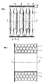
- FIG. 1 to 3 illustrate the invention.
- Figure 1 shows in section a straight portion of corrugated tube, along the longitudinal axis XX 'of this tube.
- Figure 2 shows in section the same portion of corrugated tube after winding around a Z axis.
- Figure 3 shows a fluid storage structure as obtained by the method of the invention.
- the crosses locate the centers of the successive circle portions which make up the wave, these circle portions possibly or not being separated by substantially rectilinear portions seen in section, and corresponding to substantially conical zones, in spatial representation.
- the hollow portion can be filled over substantially its entire height.
- successive hollow and raised portions can constitute successive rings, or adopt a helical shape.
- the support form of the winding when it is material, can take the form of a drum with a constant radius, but can also take different shapes, such as an oval drum, a mannequin, or even have straight portions followed by portions with a large radius of curvature, such as a frame hollow metal or a trench dug in an urban environment.
- the whole can be covered with a protective layer, for example a thin strip of helically wound rubber (3a) and a longitudinal reinforcing frame, for example a braid of metal wires (3b).
- the tube 1 is wound around a drum whose axis, perpendicular to the figure, passes through point Z (fig 2) of the axis Y′Y (fig 3).
- the impregnated reinforcing element is still deformable, and the shape of its section, initially as in FIG. 1, takes on an appearance similar to that of FIG. 2.
- the support drum assembly when it is present, and the wound tube is then subjected to the hardening treatment.
- the hardening treatment when it results from a temporary rise in temperature, can be carried out by enclosing the assembly thus constituted in an oven, but it can also be carried out, for example, by sending inside the tube. a fluid at the treatment temperature and under a pressure such that the sheath alone, reinforced only by the longitudinal reinforcement such as the metal braid, can support it, for the time necessary for the treatment.
- this same tube manufactured with the same materials, and maintained in the same curved position, had a burst pressure of 12 MPa (15% loss only instead of 50%), if the stabilization process (hardening) of the epoxy resin, in this case heating in an oven, was carried out by positioning the uncooked hose in an oven, in the position in which the test would be carried out, and by stabilizing the resin in this position .
- This tube wound on a reel with a barrel outside diameter of 0.5 m and a barrel length of 1.85 meters, is distributed over six layers for an external diameter slightly less than 1.2 m.
- This coil whose barrel and cheeks are made of sheet steel 5 mm thick, weighs itself 186 daN. With its stiffeners and its handling hooks, the carrying device reaches a weight of 235 daN, which makes a total curb weight of 858 daN, comparing advantageously with the curb weight of 1784 daN of the classic "frame", however of lower capacity.
- connection devices as described in the French patent FR-2,604,768 cited above, are intended to ensure the constancy of the diameter over the entire length of the tube, to avoid any pressure drop detrimental to the proper flow of fluids. They will preferably be used when the purpose of the tube is to transfer fluids.
- connection systems less costly and providing only a passage of reduced section compared to the section of the tube, but of the same order of magnitude as the section of the compressed gas supply pipes, can be used without depart from the scope of the invention, when the structure according to the invention is intended for the storage of compressed gases.
- the structure according to the invention results from the winding around an axis of corrugated tube packed in the hollow external portions of curable composition, and before or after the hardening treatment, to introduce a composition capable of expand around the turns of the winding, and foam this composition. If such a foaming composition is produced from phenolic resins or other resins having good behavior in the event of fire, the storage thus carried out will be, at least temporarily, protected from overheating in the event of fire.
- a corrugated tube is produced, the circumferential wave of which has the following characteristics:
- a strand of glass fiber primed in vacuo with an epoxy composition consisting of 100 parts of bisphenol A diglycidyl ether, to which 90 parts have been added, is continuously wound in the hollow of the waves.
- This prepreg has been stored in the freezer at a temperature of -18 ° C since its manufacture and allowed to warm to room temperature one hour before use.
- the filled corrugated tube After filling the waves, the filled corrugated tube passes through a banding machine which garnishes it with a thin sheet of a vulcanized elastomer of the EPDM type.
- the product thus protected against the flow of resin passes through a braiding machine which forms an aramid braid around it, then through a banding machine which deposits a ribbon of vulcanized rubber of the nitrile rubber type, 1 mm thick.
- the tube thus formed, and equipped at its first end with a plugged connection, is wound on a steel drum with an internal diameter of 0.5 m and a length of 1.85 m, equipped with circular cheeks of 1.2 m external diameter.
- a length of tube of nearly 500 meters is placed with a total internal volume of 1000 dm3.
- the second end is equipped with a connector provided with a threaded hole allowing to receive a valve, and arranged in such a way that this threaded hole is subsequently accessible without difficulty, and the assembly is placed in an oven of sufficient dimensions, then brought gradually, at a temperature rise rate of 2 ° C per minute, to a temperature of 140 ° C. This temperature is maintained for a period of one hour, then the heating is switched off and the assembly is removed from the oven.
- a threaded plug is then placed in the threaded hole of the fitting.
- a polyethylene tube 2 mm thick and 1.3 meters in diameter is placed around this assembly, and an expandable composition based on phenolic resin is poured between the packed drum and the polyethylene tube. occupy the space available between the tube serving as a reservoir and the polyethylene tube, and part of the free space between the different turns of the tube.
- the tank thus formed is then emptied of most of its water, then returned to the oven which served for its cooking so as to heat it, and connected to a source of vacuum to allow the complete drying of the pipe. , before being usable as storage of compressed gas under 20 MPa of pressure.
- the rings of epoxy glass composite material formed by the winding of the composition are not of constant shape where the tube is folded. They are of substantially constant section, but their width (measured in the longitudinal direction of the tube) and their height (measured in the radial direction of the tube) vary substantially inversely proportional to each other, the area of the ring being in the portion of tube directed towards the center of the curvature having the section having the greatest height and the smallest width, and the zone directed towards the outside of the tube having the greatest width and the lowest height.
- the variation in width and, correspondingly, in height is substantially periodic.
Landscapes
- Engineering & Computer Science (AREA)
- General Engineering & Computer Science (AREA)
- Mechanical Engineering (AREA)
- Moulding By Coating Moulds (AREA)
- Rigid Pipes And Flexible Pipes (AREA)
- Filling Or Discharging Of Gas Storage Vessels (AREA)
Abstract
La structure peut être utilisée comme conteneur de gaz comprimés.
Description
- Il est connu de transporter des gaz comprimés dans des bouteilles étanches résistant à la pression. Ces bouteilles sont le plus souvent en acier, et le poids des récipients représente de près de 10 à plus de 15 fois le poids du gaz comprimé transporté lorsque la bouteille est pleine. Le poids d'une bouteille unitaire est limité par la nécessité de pouvoir la manipuler manuellement, lorsqu'elle doit pouvoir être placée dans des lieux non accessibles par des moyens mécaniques.
- Lorsque l'utilisateur dispose de moyens mécaniques de manutention, ou lorsque l'emplacement d'utilisation est directement accessible par les camions de livraison, ces bouteilles sont souvent rassemblées en un ensemble compact appelé "CADRE". De tels cadres ont des poids très importants, par exemple un peu plus de 20 kN pour un cadre contenant 189 m³ TPN d'azote sous 20 MPa de pression (poids de l'azote contenu : 236 daN).
- De tels cadres constituant des ensembles unitaires non dissociables, il apparaît qu'ils peuvent être réalisés de façon totalement différente, et non par rassemblement de bouteilles unitaires standard.
- Un des problèmes que l'on rencontre lorsque l'on désire augmenter le diamètre des bouteilles pour accroître leur capacité à longueur constante est celui des fonds, qui doivent être hémisphériques pour présenter un poids minimum à capacité donnée, et plats pour la facilité de manutention, au moins en ce qui concerne le fond inférieur.
- Comme la facilité de manutention est l'impératif dominant, le fond inférieur est donc plat ou quasiment plat, et son épaisseur ne croît pas comme le diamètre du récipient, mais comme son cube, pour conserver des déformations acceptables. Par suite, le poids du récipient croît beaucoup plus vite que la capacité unitaire de la bouteille.
- Le procédé selon l'invention permet d'obtenir des cadres de même capacité mais beaucoup plus légers avec un encombrement comparable, ou des cadres de même poids, mais de capacité très largement supérieure.
- D'autres applications des structures obtenues conformément au procédé selon l'invention peuvent bien entendu être réalisées sans sortir du cadre de l'invention.
- Il est basé sur l'utilisation d'un récipient de grande longueur et de faible diamètre, pouvant être enroulé hélicoïdalement sur une bobine, dont le noyau central peut lui même être une bouteille standard, ou un récipient léger de conception plus récente.
- Un des problèmes que l'on rencontre lors de l'utilisation d'un tube enroulé lorsqu'on le soumet à une pression interne est sa tendance naturelle à se redresser, ce phénomène étant lié à l'ovalisation que prend le tube lorsqu'on le cintre pour le mettre en place sur la bobine.
- Sous l'effet de la pression interne, il cherche à retrouver une section de forme circulaire, ceci ne pouvant être obtenu que par ouverture des spires.
- Il est pratiquement impossible d'enrouler un tube en matériau homogène sans l'ovaliser, ce qui en fait un ressort extrèmement dangereux s'il est maintenu en position courbe sous pression. Par ailleurs, même maintenu courbe, le petit axe de l'ellipse correspondant à une section droite du tube ovalisé a tendance à gonfler de façon importante pour rechercher la section circulaire lorsqu'il est mis sous pression interne, ce qui fait que le gonflement radial (par rapport à la bobine) est très important.
- Il est par suite nécessaire de réserver des espaces importants entre deux couches de tube pour permettre la respiration de ce genre de tube.
- Ces limitations font qu'un tel stockage, sous forme d'un tube enroulé sur une bobine, n'a jamais été utilisé.
- Les tubes onduleux armés, tels que décrits dans le brevet français FR-2.553.860 (US-4.811.761), présentent la particularité de conserver une section circulaire lorsqu'ils sont courbés, et ne développent par conséquent pas de couple de redressement lorsqu'ils sont mis sous pression en position courbe.
- Pour la même raison, leur variation de diamètre dans le sens radial de la bobine se limite à l'allongement du renfort circonférenciel du tube onduleux, de l'ordre de 1 % dans le cas où le renfort est constitué de fibres de verre E, et plus faible en cas d'utilisation de fibres de carbone.
- Les espaces à réserver diamétralement seront donc beaucoup plus faibles, et l'interposition, entre le noyau et la première couche de tube, d'une couche d'un élastomère, puis entre la première et la deuxième couche, et ainsi de suite, permettra la respiration normale du tube. Si le tube renforcé comporte une gaine élastomèrique d'étanchéité, celle-ci pourra, par sa déformation locale, assurer la compensation des variations de diamètre du tube entre son état au repos et son état sous pression.
- Il a toutefois été constaté qu'un tel tube ondulé armé circonférenciellement et longitudinalement voyait ses propriétés de résistance à la pression interne baisser de façon importante lorsqu'il est fabriqué en position droite comme décrit dans le brevet précité et utilisé en position très fortement courbée, comme c'est le cas pour les couches internes dans une installation de stockage transportable telle qu'elle peut être obtenue selon l'invention.
- Le procédé de l'invention permet de fabriquer une structure creuse, utilisable notamment pour le stockage de fluides sous pression qui, bien que se présentant sous forme d'une pluralité de spires d'un tube courbé, présente une résistance à la pression interne élevée.
- Il permet également la réalisation de tubes de transfert de fluides sous pression ne présentant que très peu de pertes de résistance à la pression lorsqu'ils comportent des zones présentant de très faibles rayons de courbure, lorsque ces zones peuvent être déterminées à l'avance, ce qui est le cas, par exemple, de tubes destinés à être placés de façon définitive dans une structure telle qu'une tranchée ou l'ossature d'un bâtiment ou de stockage de fluide sous pression dans un véhicule par exemple en utilisant les espaces creux de l'ossature d'un véhicule.
- Le procédé de fabrication comprend les étapes successives suivantes:
- a) on garnit, sur au moins une partie de leur hauteur, les portions externes creuses d'un tube flexible de structure ondulées, par une composition comportant une résine durcissable renforcée de fibres,
- b) on courbe le tube ainsi garni sur au moins une partie de sa longueur de manière à le disposer selon une forme correspondant à l'utilisation qui en sera faite, et
- c) on soumet le tube ainsi courbé sur au moins une partie de sa longueur à un traitement permettant le durcissement de la composition durcissable.
- Selon des modalités préférées de réalisation, dont certaines peuvent être réalisées simultanément:
- on recouvre le tube flexible garni de la composition durcissable d'une gaine (G) de matériau substantiellement non perméable à ladite résine, de manière à maintenir celle-ci sensiblement en place dans lesdites portions externes creuses du tube ondulé, avant de procéder à l'enroulement dudit tube,
- la résine est une résine thermodurcissable et l'étape (c) est réalisée par chauffage dudit ensemble jusqu'à une température permettant le durcissement de la résine.
- La résine, lors de l'imprégnation, renferme un matériau de réticulation, et l'ensemble est maintenu à l'étape (c) dans des conditions permettant à la réticulation de se produire
- après l'étape (a) et avant l'étape (b), on dispose autour du tube garni de composition durcissable et muni ou non de la gaine (G) de matière substantiellement non perméable à la résine, une couche (H) de résistance mécanique plus élevée que celle de la gaine (G)
- la couche (H) est constituée d'une tresse de fibres de résistance mécanique élevée
- la forme d'utilisation peut être constituée d'une pluralité de spires enroulées sur un tambour
- le rayon de courbure du tube, lors de la formation des spires, est choisi de manière à rapprocher les ondulations les plus proches de l'axe d'enroulement et à écarter les ondulations les plus éloignées dudit axe, sans provoquer toutefois un écrasement du tube réduisant sensiblement son diamètre dans une direction perpendiculaire audit axe
- l'enroulement est effectué autour d'un conteneur creux sensiblement cylindrique, en communication avec ledit enroulement et pouvant constituer une partie du volume de stockage
- les extrémités du tube sont pourvues de systèmes permettant la communication avec l'extérieur ou la fermeture étanche.
- L'invention n'est pas limitée à l'emploi d'une résine thermodurcissable particulière. On pourra par exemple mélanger une résine avec son durcisseur pour imprégner les filaments qui serviront à garnir les portions externes creuses du tube ondulé, et chauffer ensuite, en position courbe du tube. On peut aussi réaliser une vulcanisation en garnissant les ondes de filaments préalablement imprégnés de latex additionné de soufre et en chauffant après enroulement du tube. On peut ainsi utiliser une résine formo-phénolique, une résine mélamine formaldéhyde, une résine urée-formaldéhyde, une résine époxyde, une résine polyester ou vinylester, ou une résine alkyde, ou mettre en place dans les portions externes creuses du tube ondulé des mèches constituées d'un mélange de fibres renforçantes et de fibres thermoplastiques fusibles telles que des fibres de polyamide ou de polyéthylène, ou des mèches de fibres renforçantes garnies de poudre de résine thermoplastique fusible, puis, après enroulement, procéder à un traitement thermique permettant d'obtenir la fusion du thermoplastique avant de procéder au refroidissement assurant le durcissement de l'ensemble.
- La gaine (G) déposée éventuellement peut être un simple enroulement hélicoïdal d'une bande de matériau plastique ou élastomèrique dont l'épaisseur peut être faible, puisque cette bande, après durcissement de la résine, n'a normalement plus de rôle à jouer.
- Les figures 1 à 3 illustrent l'invention.
- La figure 1 montre en coupe une portion droite de tube ondulé, selon l'axe longitudinal XX′ de ce tube.
- La figure 2 montre en coupe la même portion de tube ondulé après enroulement autour d'un axe Z.
- La figure 3 montre une structure de stockage de fluides telle qu'obtenue par le procédé de l'invention.
- Sur ces figures, dans un but de simplification, on n'a pas représenté les extrémités libres du tube, qui peuvent être équipées de raccords, tels ceux du brevet Français FR-2.604.768.
- Sur la figure 1, la totalité des portions creuses (2a, 2b, 2c) du tube ondulé droit sont remplies de résine, mais on peut également ne remplir qu'une partie, à partir du fond, jusqu'à la zone où le rayon de courbure de la zone externe de l'ondulation de la gaine devient sensiblement constant.
- Les croix situent les centres des portions de cercle successives qui contituent l'onde, ces portions de cercle pouvant être séparées, ou non, par des portions sensiblement rectilignes vues en coupe, et correspondant à des zones sensiblement coniques, en représentation spatiale.
- La forme représentée, en demi cercles successifs, n'est pas obligatoire et toute autre forme peut être utilisée, pourvu qu'elle présente des cannelures. Une structure de type "accordéon" peut ainsi être utilisée.
- Dans ce cas, la portion creuse pourra être garnie sur sensiblement toute sa hauteur.
- Si l'on considère les portions creuses et en relief successives, elles peuvent constituer des anneaux successifs, ou adopter une forme hélicoïdale.
La forme support de l'enroulement, lorsqu'elle est matérielle, peut prendre la forme d'un tambour présentant un rayon constant, mais peut également prendre des formes différentes, telle qu'un tambour ovale, un mannequin, ou même présenter des portions droites suivies de portions à fort rayon de courbure, telle qu'un cadre métallique creux ou une tranchée creusée en environnement urbain. - Lors de la fabrication, on part du tube ondulé droit 1, et on dépose au moins un élément de renfort imprégné d'une résine durcissable dans les portions creuses (2a,2b,2c) de ce tube. On peut recouvrir le tout d'une couche protectrice, par exemple une bande mince de caoutchouc enroulée hélicoïdalement(3a) et une armature de renfort longitudinal, par exemple une tresse de fils métalliques (3b).
- On enroule le tube 1 autour d'un tambour dont l'axe, perpendiculaire à la figure, passe par le point Z (fig 2) de l'axe Y′Y (fig 3). Comme la résine n'a pas pris sa forme définitive, l'élément de renfort imprégné est encore déformable, et la forme de sa section, initialement telle que sur la figure 1, prend un aspect semblable à celui de la figure 2.
- L'ensemble tambour support quand il est présent, et tube enroulé est alors soumis au traitement de durcissement.
- Le traitement de durcissement, lorsqu'il résulte d'une élévation temporaire de la température, peut être effectué en enfermant l'ensemble ainsi constitué dans une étuve, mais il peut aussi être effectué, par exemple, en envoyant à l'intérieur du tube un fluide à la température de traitement et sous une pression telle que la gaine seule, renforcée seulement par l'armature longitudinale telle que la tresse métallique, puisse la supporter, pendant la durée nécessaire au traitement.
- A titre d'élément de comparaison de l'art antérieur, un tube de diamètre intérieur 49 mm, de diamètre extérieur 56 mm, constitué d'une feuille ondulée de polyfluorure de vinylidène de 0,5 mm d'épaisseur, dont les portions creuses externes sont garnies sur la presque totalité de leur hauteur, de fibres de verre E imprégnées d'une composition époxyde, l'imprégnation ayant été réalisée conformément au procédé décrit dans le brevet français FR-2.630.464, le durcissement ayant été effectué de façon conventionnelle, ledit tube ayant été ensuite armé longitudinalement d'une tresse d'aramide, et équipé de raccords suivant le brevet français FR-2.604.768, présente une pression d'éclatement de 14 MPa lorsqu'il est sollicité en position droite (linéaire). L'éclatement intervient par percement de la gaine de polyfluorure de vinylidène au sommet de l'onde externe.
- Fabriqué de la même façon, avec les mêmes produits, sa pression d'éclatement n'est plus que de 7 MPa lorsqu'il est sollicité en position courbe, avec un rayon de courbure de 35 cm (posé sur une bobine de diamètre de fût de 70 cm).
- Il a été constaté que ce même tube, fabriqué avec les mêmes matériaux, et maintenu dans la même position courbe, avait une pression d'éclatement de 12 MPa (15 % de perte seulement au lieu de 50 %), si le processus de stabilisation (durcissement) de la résine époxyde, en l'occurence un chauffage en étuve, était effectué en positionnant le flexible non cuit en étuve, dans la position dans laquelle l'essai serait effectué, et en effectuant la stabilisation de la résine dans cette position.
- Un flexible de même diamètre, réalisé avec une gaine d'acier inoxydable ondulée de 0,25 mm d'épaisseur, fabriqué, stabilisé et essayé en position droite, présente une pression d'éclatement de 63 MPa. Il est donc envisageable de s'en servir comme tube de stockage travaillant sous 20 à 21 MPa. Fabriqué et stabilisé droit, mais essayé courbe (même rayon de courbure que ci-dessus), sa pression d'éclatement est ramenée à 35 MPa, ce qui est trop peu pour une utilisation sous 20 à 21 MPa. Fabriqué droit, mais stabilisé après courbure, ce même flexible présente une pression d'éclatement de 60 MPa (la perte n'est plus que de 5 %), et peut être utilisé, avec une telle courbure, comme récipient de stockage pour des gaz comprimés sous 20 MPa.
- Son poids, équipé de la tresse d'aramide et d'une gaine externe en caoutchouc de 1 mm d'épaisseur, est de 12,55 N/m, pour un volume interne de 2,015 dm³/m. Pour disposer d'un volume interne de stockage de 1 m3, il faut utiliser 496 mètres de ce tube, représentant un poids de 623 daN.
- Ce tube, enroulé sur une bobine de diamètre extérieur de fût de 0,5 m et de longueur de fût 1,85 mètre, se repartit sur six couches pour un diamètre externe légèrement inférieur à 1,2 m. Cette bobine, dont le fût et les joues sont réalisés en tôle d'acier de 5 mm d'épaisseur, pèse elle-même 186 daN. Avec ses raidisseurs et ses crochets de manutention, le dispositif porteur atteint un poids de 235 daN, ce qui fait un poids à vide total de 858 daN, se comparant avantageusement avec le poids à vide de 1784 daN du "cadre" classique, pourtant de capacité inférieure.
- Les dispositifs de raccordement tels que décrits dans le brevet français FR-2.604.768 cité ci-dessus, sont destinés à assurer la constance du diamètre sur toute la longueur du tube, pour éviter toute perte de charge préjudiciable au bon écoulement des fluides. Ils seront utilisés préférentiellement lorsque le but du tube est de transférer des fluides.
- D'autres systèmes de raccordement, moins coûteux et n'assurant qu'un passage de section réduite par rapport à la section du tube, mais du même ordre de grandeur que la section des conduites d'alimentation en gaz comprimés, peuvent être utilisés sans sortir du cadre de l'invention, lorsque la structure suivant l'invention est destinée au stockage de gaz comprimés.
- Il est possible, lorsque la structure selon l'invention résulte de l'enroulement autour d'un axe de tube ondulé garni dans les portions externes creuses de composition durcissable, et avant ou après le traitement de durcissement, d'introduire une composition susceptible de s'expanser autour des spires de l'enroulement, et de procéder au moussage de cette composition. Si une telle composition moussante est réalisée à partir de résines phénoliques ou d'autres résines ayant un bon comportement en cas d'incendie, le stockage ainsi réalisé sera, au moins temporairement, protégé de l'échauffement en cas d'incendie.
- L'invention sera mieux comprise en suivant l'exemple de réalisation ci-dessous indiqué.
- Par des procédés connus par ailleurs, on réalise un tube ondulé dont l'onde, circonférencielle, présente les caractéristiques suivantes:

- Au moyen d'un dispositif sans centre, on bobine en continu, dans le creux des ondes, une mèche de fibres de verre primprégnée sous vide d'une composition époxyde constituée de 100 parties de diglycidyléther de bisphénol A, auxquelles ont été ajoutées 90 parties d'anhydride méthylendométhylènetétrahydrophtalique et 2 parties de benzyldiméthylamine. Ce préimprégné a été conservé au congélateur à une température de -18°C depuis sa fabrication et mis à réchauffer à température ambiante une heure avant son utilisation.
- On effectue autour de chaque onde un nombre de tours suffisant pour la remplir de manière pratiquement complète, puis on passe à l'onde suivante.
- Après remplissage des ondes, le tube ondulé garni passe dans une rubanneuse qui le garnit d'une feuille mince d'un élastomère vulcanisé du type EPDM.
- Le produit ainsi protégé contre l'écoulement de la résine passe dans une tresseuse qui forme autour de lui une tresse d'aramide, puis dans une rubanneuse qui dépose à sa surface un ruban de caoutchouc vulcanisé du type caoutchouc nitrile de 1 mm d'épaisseur.
- Le tube ainsi constitué, et équipé à sa première extrémité d'un raccord bouché, est enroulé sur un tambour d'acier de diamètre intérieur 0,5 m et de longueur 1,85 m, équipé de joues circulaires de 1,2 m de diamètre externe. On place ainsi, en six couches, une longueur de tube de près de 500 mètres ayant un volume interne total de 1000 dm³. La seconde extrémité est équipée d'un raccord muni d'un trou fileté permettant de recevoir une vanne, et disposé de facon à ce que ce trou fileté soit ultérieurement accessible sans difficulté, et l'ensemble est placé dans une étuve de dimensions suffisante, puis porté progressivement, à une vitesse de montée en température de 2°C par minute, jusqu'à une température de 140°C. Cette température est maintenue pendant une durée d'une heure, puis le chauffage est coupé et l'ensemble sorti de l'étuve. On place alors un bouchon fileté dans le trou fileté du raccord.
- On place autour de cet ensemble un tube de polyéthylène de 2 mm d'épaisseur et de 1,3 mètre de diamètre, et l'on coule entre le tambour garni et le tube de polyéthylène une composition expansible à base de résine phénolique, qui vient occuper l'espace disponible entre le tube servant de réservoir et le tube de polyéthylène, et une partie de l'espace libre entre les différentes spires du tube.
- On enlève alors le bouchon protecteur du trou fileté et place une vanne permettant un raccordement à un réseau d'eau pour garnir l'ensemble d'eau et effectuer un essai de pression interne à une pression de 30 MPa. Cette pression est soutenue sans modification dimensionnelle apparente de l'ensemble.
- Le réservoir ainsi constitué est ensuite vidé de la plus grande partie de son eau, puis remis dans l'étuve qui a servi pour sa cuisson de façon à l'échauffer, et raccordé à une source de vide pour permettre le séchage total de la canalisation, avant d'être utilisable comme stockage de gaz comprimé sous 20 MPa de pression.
- Les anneaux de matériau composite verre époxy constitués par l'enroulement de la composition ne sont pas de forme constante là où le tube est replié. Ils sont de section sensiblement constante, mais leur largeur (mesurée dans le sens longitudinal du tube) et leur hauteur (mesurée dans le sens radial du tube) varient de façon sensiblement inversement proportionnelle l'une par rapport à l'autre, la zone de l'anneau se trouvant dans la portion de tube dirigée vers le centre de la courbure ayant la section présentant la plus grande hauteur et la plus faible largeur, et la zone dirigée vers l'extérieur du tube présentant la plus grande largeur et la plus faible hauteur.
- Dans le cas d'ondulations hélicoïdales la variation de largeur et, corrélativement, de hauteur, est sensiblement périodique.
Claims (12)
Applications Claiming Priority (2)
| Application Number | Priority Date | Filing Date | Title |
|---|---|---|---|
| FR9005507A FR2661477B1 (fr) | 1990-04-26 | 1990-04-26 | Procede de fabrication d'une structure creuse utilisable notamment pour le stockage de fluides sous pression et structure resultante. |
| FR9005507 | 1990-04-26 |
Publications (2)
| Publication Number | Publication Date |
|---|---|
| EP0458666A1 true EP0458666A1 (fr) | 1991-11-27 |
| EP0458666B1 EP0458666B1 (fr) | 1995-07-05 |
Family
ID=9396243
Family Applications (1)
| Application Number | Title | Priority Date | Filing Date |
|---|---|---|---|
| EP91401030A Expired - Lifetime EP0458666B1 (fr) | 1990-04-26 | 1991-04-18 | Procédé de fabrication d'une structure creuse utilisable notamment pour le stockage de fluides sous pression |
Country Status (8)
| Country | Link |
|---|---|
| US (1) | US5830400A (fr) |
| EP (1) | EP0458666B1 (fr) |
| JP (1) | JP3251948B2 (fr) |
| CA (1) | CA2041291C (fr) |
| DE (1) | DE69110981T2 (fr) |
| DK (1) | DK0458666T3 (fr) |
| ES (1) | ES2077191T3 (fr) |
| FR (1) | FR2661477B1 (fr) |
Cited By (1)
| Publication number | Priority date | Publication date | Assignee | Title |
|---|---|---|---|---|
| EP0946387A4 (fr) * | 1996-10-01 | 2002-10-09 | Williams Energy Marketing & Trading | Systeme de transport de gaz par bateau |
Families Citing this family (25)
| Publication number | Priority date | Publication date | Assignee | Title |
|---|---|---|---|---|
| FR2669396B1 (fr) * | 1990-11-19 | 1997-05-09 | Inst Francais Du Petrole | Reservoir de poids unitaire faible utilisable notamment pour le stockage de fluides sous pression et son procede de fabrication. |
| FR2706578B1 (fr) * | 1993-06-18 | 1995-09-01 | Inst Francais Du Petrole | Réservoir de stockage d'hydrocarbures sous pression. |
| FR2720142B1 (fr) * | 1994-05-20 | 1996-06-28 | Inst Francais Du Petrole | Structure légère PA-12-carbone pour le stockage de fluides sous pression. |
| US6513522B1 (en) | 2000-06-13 | 2003-02-04 | Mallinckrodt Inc. | Wearable storage system for pressurized fluids |
| US6502571B1 (en) | 2000-06-13 | 2003-01-07 | Mallinckrodt Inc. | High pressure fitting with dual locking swaging mechanism |
| US6345730B1 (en) | 2000-06-13 | 2002-02-12 | Mallinckrodt Inc. | Adhesively connected polymeric pressure chambers and method for making the same |
| US6412484B1 (en) | 2000-06-13 | 2002-07-02 | Mallinckrodt Inc. | Fluid control valve for pressure vessel |
| US6412801B1 (en) | 2000-11-01 | 2002-07-02 | Mallinckrodt Inc. | Wheeled personal transport device incorporating gas storage vessel comprising a polymeric container system for pressurized fluids |
| US6579401B1 (en) | 2000-11-01 | 2003-06-17 | Mallinckrodt, Inc. | Method for forming a polymeric container system for pressurized fluids |
| US6536425B1 (en) | 2000-11-01 | 2003-03-25 | Mallinckrodt Inc. | Litter incorporating gas storage vessel comprising a polymeric container system for pressurized fluids |
| US6526968B1 (en) | 2000-11-08 | 2003-03-04 | Mallinckrodt Inc. | Utility belt incorporating a gas storage vessel |
| US6453920B1 (en) | 2000-11-08 | 2002-09-24 | Mallinckrodt Inc. | Walking assistance device incorporating gas storage vessel comprising a polymeric container system for pressurized fluids |
| US6510850B1 (en) | 2000-11-08 | 2003-01-28 | Mallinckrodt Inc. | Emergency breathing apparatus incorporating gas storage vessel comprising a polymeric container system for pressurized fluids |
| US6513523B1 (en) | 2000-11-08 | 2003-02-04 | Mallinckrodt Inc. | Wearable belt incorporating gas storage vessel comprising a polymeric container system for pressurized fluids |
| US6527075B1 (en) | 2000-11-08 | 2003-03-04 | Mallinckrodt Inc. | Vehicle incorporating gas storage vessel comprising a polymeric container system for pressurized fluids |
| US6983769B2 (en) * | 2003-06-23 | 2006-01-10 | Tokai Rubber Industries, Ltd. | Vibration absorbing hose |
| WO2012171832A1 (fr) * | 2011-06-16 | 2012-12-20 | Reinhardt, Gaby Traute | Dispositif d'accumulation de pression |
| WO2016205372A2 (fr) * | 2015-06-15 | 2016-12-22 | Other Lab Llc | Système et procédé pour récipient de pression adaptable |
| CN108431486A (zh) | 2015-12-02 | 2018-08-21 | 奥特尔实验室有限责任公司 | 用于衬筒编织和树脂涂敷的系统和方法 |
| US10054267B2 (en) | 2016-05-27 | 2018-08-21 | GM Global Technology Operations LLC | Pressure vessel array |
| WO2018081107A1 (fr) | 2016-10-24 | 2018-05-03 | Other Lab Llc | Raccords pour récipients de stockage de gaz comprimé |
| WO2018183767A1 (fr) | 2017-03-31 | 2018-10-04 | Other Lab, Llc | Système et procédé de remplissage de réservoir |
| RU2665564C1 (ru) * | 2017-07-28 | 2018-08-31 | Общество с ограниченной ответственностью "Инжиниринговый сервис и консалтинг" (ООО "ИнСК") | Система для хранения топливных газов |
| CN109624301B (zh) * | 2018-12-29 | 2020-10-30 | 重庆赛格尔汽车配件有限公司 | 波纹管穿合装置 |
| EP3935306A2 (fr) * | 2019-03-05 | 2022-01-12 | Linamar Corporation | Procédés de prévention contre une défaillance de tuyau annelé dans des récipients sous pression de type iv |
Citations (2)
| Publication number | Priority date | Publication date | Assignee | Title |
|---|---|---|---|---|
| DE8518194U1 (de) * | 1985-06-22 | 1985-09-12 | Witzenmann GmbH, Metallschlauch-Fabrik Pforzheim, 7530 Pforzheim | Biegbarer, fluiddichter Schlauch oder Balg mit einer Umhüllung zur Längsabstützung |
| US4576015A (en) * | 1983-04-14 | 1986-03-18 | Crawford A Gerrit | Lightweight high pressure tubular storage system for compressed gas and method for cryogenic pressurization |
Family Cites Families (15)
| Publication number | Priority date | Publication date | Assignee | Title |
|---|---|---|---|---|
| US2998985A (en) * | 1958-05-02 | 1961-09-05 | Mc Graw Edison Co | Short radius, fibre, pipe bend |
| GB1491206A (en) * | 1973-11-08 | 1977-11-09 | Atomic Energy Authority Uk | Catalyst bodies |
| US4091063A (en) * | 1974-07-11 | 1978-05-23 | Dayco Corporation | Hose construction and method of making same |
| US4205034A (en) * | 1975-06-02 | 1980-05-27 | The Gates Rubber Company | Method for making a reinforced tubular article |
| US4158586A (en) * | 1976-08-25 | 1979-06-19 | Fumio Usui | Method for producing bent pipe of reinforced synthetic resin |
| US4360493A (en) * | 1981-07-09 | 1982-11-23 | Kramer Sr Vance M | Flexible corrugated rubber tubing of dual composition |
| US4400338A (en) * | 1982-02-16 | 1983-08-23 | Tremco, Incorporated | Method for making sealant |
| NZ207219A (en) * | 1984-02-20 | 1988-10-28 | Rib Loc Int Ltd | Helically wound tube formed from flat strip with interlocking edge ribs |
| NL8502327A (nl) * | 1985-08-23 | 1987-03-16 | Wavin Bv | Kunststofbuis bestaande uit een buitenhuis met ribbels en gladde binnenwand, alsmede werkwijze voor het herstellen resp. verbeteren van een rioleringsbuis. |
| US4780946A (en) * | 1985-09-12 | 1988-11-01 | Palazzo David T | Method of making double wall storage tank with beaded spacer means |
| JPS6292833A (ja) * | 1985-10-19 | 1987-04-28 | Nitto Boseki Co Ltd | 湾曲した連続繊維強化樹脂管の製造法 |
| FR2600747B1 (fr) * | 1986-06-30 | 1988-12-30 | Inst Francais Du Petrole | Tube flexible utilisable notamment pour le transport de fluides caloporteurs ou frigorifiques |
| FR2604768B1 (fr) * | 1986-10-07 | 1988-12-30 | Inst Francais Du Petrole | Raccord et procede de fabrication de ce raccord pour arbre comportant une armature de renfort |
| US4804019A (en) * | 1987-02-12 | 1989-02-14 | Kramer Jr Vance M | End adaptor for flexible corrugated tube |
| FR2630464B1 (fr) * | 1988-04-22 | 1990-09-28 | Inst Francais Du Petrole | Procede et dispositif pour preimpregner des elements de renfort utilisables pour realiser un materiau composite, produit obtenu |
-
1990
- 1990-04-26 FR FR9005507A patent/FR2661477B1/fr not_active Expired - Lifetime
-
1991
- 1991-04-18 EP EP91401030A patent/EP0458666B1/fr not_active Expired - Lifetime
- 1991-04-18 DK DK91401030.1T patent/DK0458666T3/da active
- 1991-04-18 ES ES91401030T patent/ES2077191T3/es not_active Expired - Lifetime
- 1991-04-18 DE DE69110981T patent/DE69110981T2/de not_active Expired - Fee Related
- 1991-04-26 CA CA002041291A patent/CA2041291C/fr not_active Expired - Fee Related
- 1991-04-26 JP JP13066891A patent/JP3251948B2/ja not_active Expired - Fee Related
-
1995
- 1995-12-06 US US08/568,360 patent/US5830400A/en not_active Expired - Fee Related
Patent Citations (2)
| Publication number | Priority date | Publication date | Assignee | Title |
|---|---|---|---|---|
| US4576015A (en) * | 1983-04-14 | 1986-03-18 | Crawford A Gerrit | Lightweight high pressure tubular storage system for compressed gas and method for cryogenic pressurization |
| DE8518194U1 (de) * | 1985-06-22 | 1985-09-12 | Witzenmann GmbH, Metallschlauch-Fabrik Pforzheim, 7530 Pforzheim | Biegbarer, fluiddichter Schlauch oder Balg mit einer Umhüllung zur Längsabstützung |
Cited By (1)
| Publication number | Priority date | Publication date | Assignee | Title |
|---|---|---|---|---|
| EP0946387A4 (fr) * | 1996-10-01 | 2002-10-09 | Williams Energy Marketing & Trading | Systeme de transport de gaz par bateau |
Also Published As
| Publication number | Publication date |
|---|---|
| FR2661477B1 (fr) | 1992-07-10 |
| JPH04228998A (ja) | 1992-08-18 |
| DK0458666T3 (da) | 1995-08-21 |
| FR2661477A1 (fr) | 1991-10-31 |
| DE69110981D1 (de) | 1995-08-10 |
| ES2077191T3 (es) | 1995-11-16 |
| CA2041291A1 (fr) | 1991-10-27 |
| CA2041291C (fr) | 2002-01-22 |
| EP0458666B1 (fr) | 1995-07-05 |
| JP3251948B2 (ja) | 2002-01-28 |
| US5830400A (en) | 1998-11-03 |
| DE69110981T2 (de) | 1995-11-16 |
Similar Documents
| Publication | Publication Date | Title |
|---|---|---|
| EP0458666B1 (fr) | Procédé de fabrication d'une structure creuse utilisable notamment pour le stockage de fluides sous pression | |
| EP0487374B1 (fr) | Réservoir de poids unitaire faible utilisable notamment pour le stockage de fluides sous pression et son procédé de fabrication | |
| EP0497687B1 (fr) | Procédé de fabrication d'une structure légère par expansion d'un réservoir métallique dans un tube ondulé armé | |
| CA2515023C (fr) | Manchon a insert pour la reparation d'une canalisation de transport de fluide a haute pression. | |
| EP0060856B1 (fr) | Procede pour renforcer un corps creux realise par enroulements d'un profile, profile pour sa mise en oeuvre et canalisations renforcees obtenues | |
| EP0527932A1 (fr) | Preforme et procede pour tuber et/ou chemiser un volume cylindrique | |
| EP0067162A1 (fr) | Procede de formage d'une conduite laminee | |
| FR2937396A1 (fr) | Canalisation pour tuyauterie de transfert de fluides de vehicule aerien ou spatial, son procede de fabrication et structure aeronautique l'incorporant | |
| FR3028913A1 (fr) | Couche d'isolation thermique pour conduite tubulaire flexible sous-marine | |
| EP2949449A1 (fr) | Réservoir destiné au stockage de milieux liquides ou gazeux sous pression et son procédé de fabrication | |
| CN104094037A (zh) | 带有复合材料凸台的压力容器 | |
| US20150102037A1 (en) | Single-layer composite pressure vessel | |
| FR2720142A1 (fr) | Structure légère PA-12-carbone pour le stockage de fluides sous pression. | |
| EP1067300B1 (fr) | Réservoir en matériau composite destiné au stockage de gaz liquéfié sous pression | |
| WO2012072894A1 (fr) | Conduite rigide-déroulée avec gaine polymère et méthode de fabrication de la conduite rigide-déroulée | |
| WO2001027520A1 (fr) | Conteneur pour fluide sous pression et son procede de fabrication | |
| EP0618400B1 (fr) | Enceinte métallique pour fluide sous pression et procédé de renforcement d'une telle enceinte | |
| FR3030679A1 (fr) | Reservoir pour gaz sous pression a liner ultra mince | |
| FR2928439A1 (fr) | Reservoir de gaz sous pression et procede de fabrication d'un tel reservoir | |
| EP0481850B1 (fr) | Procédé pour fretter et maintenir sous pression un noyau par une enveloppe en matériau composite et appareillage pour la mise en oeuvre d'un tel procédé | |
| EP0075008A1 (fr) | Unites de reservoirs chemisees pour le transport de materiaux corrosifs | |
| FR2889285A1 (fr) | Canalisation stationnaire souterraine pour transport de carburant et procede de fabrication | |
| CA2576710A1 (fr) | Canalisation souterraine pour le transport de carburant | |
| FR3106185A1 (fr) | Embout pour un réservoir de fluide sous pression | |
| EP4136381A1 (fr) | Procede de realisation d'un reservoir de stockage composite |
Legal Events
| Date | Code | Title | Description |
|---|---|---|---|
| PUAI | Public reference made under article 153(3) epc to a published international application that has entered the european phase |
Free format text: ORIGINAL CODE: 0009012 |
|
| AK | Designated contracting states |
Kind code of ref document: A1 Designated state(s): BE DE DK ES GB IT LU NL SE |
|
| 17P | Request for examination filed |
Effective date: 19920320 |
|
| 17Q | First examination report despatched |
Effective date: 19940202 |
|
| ITF | It: translation for a ep patent filed | ||
| GRAA | (expected) grant |
Free format text: ORIGINAL CODE: 0009210 |
|
| AK | Designated contracting states |
Kind code of ref document: B1 Designated state(s): BE DE DK ES GB IT LU NL SE |
|
| GBT | Gb: translation of ep patent filed (gb section 77(6)(a)/1977) |
Effective date: 19950704 |
|
| REF | Corresponds to: |
Ref document number: 69110981 Country of ref document: DE Date of ref document: 19950810 |
|
| REG | Reference to a national code |
Ref country code: DK Ref legal event code: T3 |
|
| REG | Reference to a national code |
Ref country code: ES Ref legal event code: FG2A Ref document number: 2077191 Country of ref document: ES Kind code of ref document: T3 |
|
| PLBE | No opposition filed within time limit |
Free format text: ORIGINAL CODE: 0009261 |
|
| STAA | Information on the status of an ep patent application or granted ep patent |
Free format text: STATUS: NO OPPOSITION FILED WITHIN TIME LIMIT |
|
| 26N | No opposition filed | ||
| REG | Reference to a national code |
Ref country code: GB Ref legal event code: IF02 |
|
| PGFP | Annual fee paid to national office [announced via postgrant information from national office to epo] |
Ref country code: SE Payment date: 20020325 Year of fee payment: 12 |
|
| PGFP | Annual fee paid to national office [announced via postgrant information from national office to epo] |
Ref country code: GB Payment date: 20020328 Year of fee payment: 12 |
|
| PGFP | Annual fee paid to national office [announced via postgrant information from national office to epo] |
Ref country code: DK Payment date: 20020422 Year of fee payment: 12 |
|
| PGFP | Annual fee paid to national office [announced via postgrant information from national office to epo] |
Ref country code: LU Payment date: 20020425 Year of fee payment: 12 |
|
| PGFP | Annual fee paid to national office [announced via postgrant information from national office to epo] |
Ref country code: ES Payment date: 20020429 Year of fee payment: 12 Ref country code: BE Payment date: 20020429 Year of fee payment: 12 |
|
| PGFP | Annual fee paid to national office [announced via postgrant information from national office to epo] |
Ref country code: NL Payment date: 20020430 Year of fee payment: 12 |
|
| PGFP | Annual fee paid to national office [announced via postgrant information from national office to epo] |
Ref country code: DE Payment date: 20020503 Year of fee payment: 12 |
|
| PG25 | Lapsed in a contracting state [announced via postgrant information from national office to epo] |
Ref country code: LU Free format text: LAPSE BECAUSE OF NON-PAYMENT OF DUE FEES Effective date: 20030418 Ref country code: GB Free format text: LAPSE BECAUSE OF NON-PAYMENT OF DUE FEES Effective date: 20030418 |
|
| PG25 | Lapsed in a contracting state [announced via postgrant information from national office to epo] |
Ref country code: SE Free format text: LAPSE BECAUSE OF NON-PAYMENT OF DUE FEES Effective date: 20030419 Ref country code: ES Free format text: LAPSE BECAUSE OF NON-PAYMENT OF DUE FEES Effective date: 20030419 |
|
| PG25 | Lapsed in a contracting state [announced via postgrant information from national office to epo] |
Ref country code: DK Free format text: LAPSE BECAUSE OF NON-PAYMENT OF DUE FEES Effective date: 20030430 Ref country code: BE Free format text: LAPSE BECAUSE OF NON-PAYMENT OF DUE FEES Effective date: 20030430 |
|
| BERE | Be: lapsed |
Owner name: INSTITUT FRANCAIS DU *PETROLE Effective date: 20030430 |
|
| PG25 | Lapsed in a contracting state [announced via postgrant information from national office to epo] |
Ref country code: NL Free format text: LAPSE BECAUSE OF NON-PAYMENT OF DUE FEES Effective date: 20031101 Ref country code: DE Free format text: LAPSE BECAUSE OF NON-PAYMENT OF DUE FEES Effective date: 20031101 |
|
| NLV4 | Nl: lapsed or anulled due to non-payment of the annual fee |
Effective date: 20031101 |
|
| REG | Reference to a national code |
Ref country code: DK Ref legal event code: EBP |
|
| EUG | Se: european patent has lapsed | ||
| GBPC | Gb: european patent ceased through non-payment of renewal fee |
Effective date: 20030418 |
|
| REG | Reference to a national code |
Ref country code: ES Ref legal event code: FD2A Effective date: 20030419 |
|
| PG25 | Lapsed in a contracting state [announced via postgrant information from national office to epo] |
Ref country code: IT Free format text: LAPSE BECAUSE OF NON-PAYMENT OF DUE FEES;WARNING: LAPSES OF ITALIAN PATENTS WITH EFFECTIVE DATE BEFORE 2007 MAY HAVE OCCURRED AT ANY TIME BEFORE 2007. THE CORRECT EFFECTIVE DATE MAY BE DIFFERENT FROM THE ONE RECORDED. Effective date: 20050418 |