EP0458966B1 - Gemischte matrix-bildverarbeitung zur wiedergabe von halbtonbildern mit veränderlicher punktgrösse - Google Patents
Gemischte matrix-bildverarbeitung zur wiedergabe von halbtonbildern mit veränderlicher punktgrösse Download PDFInfo
- Publication number
- EP0458966B1 EP0458966B1 EP91907200A EP91907200A EP0458966B1 EP 0458966 B1 EP0458966 B1 EP 0458966B1 EP 91907200 A EP91907200 A EP 91907200A EP 91907200 A EP91907200 A EP 91907200A EP 0458966 B1 EP0458966 B1 EP 0458966B1
- Authority
- EP
- European Patent Office
- Prior art keywords
- matrix
- elements
- threshold values
- density
- series
- Prior art date
- Legal status (The legal status is an assumption and is not a legal conclusion. Google has not performed a legal analysis and makes no representation as to the accuracy of the status listed.)
- Expired - Lifetime
Links
- 239000011159 matrix material Substances 0.000 title claims abstract description 44
- 238000012545 processing Methods 0.000 title abstract description 8
- 238000009877 rendering Methods 0.000 title description 2
- 230000003287 optical effect Effects 0.000 claims abstract description 12
- 238000005070 sampling Methods 0.000 claims description 2
- 238000012935 Averaging Methods 0.000 claims 1
- 238000000034 method Methods 0.000 description 15
- 238000012216 screening Methods 0.000 description 10
- 239000006185 dispersion Substances 0.000 description 5
- 239000004020 conductor Substances 0.000 description 3
- 238000007639 printing Methods 0.000 description 3
- 230000012010 growth Effects 0.000 description 2
- 230000003044 adaptive effect Effects 0.000 description 1
- 238000010009 beating Methods 0.000 description 1
- 238000004891 communication Methods 0.000 description 1
- 230000007423 decrease Effects 0.000 description 1
- 238000005516 engineering process Methods 0.000 description 1
- 230000007773 growth pattern Effects 0.000 description 1
- 238000012986 modification Methods 0.000 description 1
- 230000004048 modification Effects 0.000 description 1
- 238000013139 quantization Methods 0.000 description 1
- 238000012552 review Methods 0.000 description 1
- 239000007787 solid Substances 0.000 description 1
- 230000001360 synchronised effect Effects 0.000 description 1
- 230000000007 visual effect Effects 0.000 description 1
Images


Classifications
-
- H—ELECTRICITY
- H04—ELECTRIC COMMUNICATION TECHNIQUE
- H04N—PICTORIAL COMMUNICATION, e.g. TELEVISION
- H04N1/00—Scanning, transmission or reproduction of documents or the like, e.g. facsimile transmission; Details thereof
- H04N1/40—Picture signal circuits
- H04N1/405—Halftoning, i.e. converting the picture signal of a continuous-tone original into a corresponding signal showing only two levels
Definitions
- This invention relates generally to encoding pictorial imagery for reproduction on binary display and/or printing systems, and more particularly to increasing the number of discernible gray levels in halftone reproduction.
- Binary displays and printers are capable of making a mark, usually in the form of a dot, of a given, uniform size and at a specified resolution in marks per unit length, typically dots per inch. It has been common to place the marks according to a variety of geometrical patterns such that a group of marks when seen by the eye gives a rendition of an intermediate color tone between the color of the background (usually white paper stock) and total coverage, or solid density.
- Continuous tone images contain an apparent continuum of gray levels. Some scenes, when viewed by humans, may require more than 256 discrete gray levels to give the appearance of a continuum of gray levels from one shade to another.
- one picture element on the recording or display surface consists of a j x k matrix of sub-elements where j and k are positive integers.
- a halftone image is reproduced by printing the respective sub-elements or leaving them blank. That is, by suitably distributing the printed marks.
- Halftone image processing algorithms are evaluated in part, by their capability of delivering a complete gray scale at normal viewing distances.
- the capability of a particular process to reproduce high frequency renditions (fine detail) with high contrast modulation makes that procedure superior to one which reproduces such fine detail with lesser or no output contrast.
- Another measure of image processing algorithm merit is the tendency to produce visual details in the output image that are not part of the original image, but are the result of the image processing algorithm. Such details are called artifacts, and include moire patterns, false contours, and false textures. Moire patterns are false details created most often by the beating between two relatively high frequency processes resulting in a signal whose spacial frequency is low enough to be seen by the viewer. False contours are the result of gray scale quantization steps which are sufficiently large to create a visible contour when the input image is truly a smooth, gradual variation from one to the other. False textures are artificial changes in the image texture which occur when input gray levels vary slowly and smoothly and the output generates an artificial boundary between the textural patterns for one gray level and the textural patterns for the next gray level.
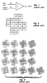
- Figure 1 shows a schematic view of the electronic screening process.
- Signal X i represents the lightness or gray level information at a sampling point i of an image.
- Input signal X i of sample image picture elements is compared with a series of threshold values C i selected in sequential order from a two-dimensional matrix defined to be the halftone cell threshold set, and a print/no-print decision is made.
- the series of threshold values and their arrangement within the threshold set determine the gray scale range, the frequency, angle, and other properties of the halftone pictorial image.
- Each threshold level C i is determined by a comparison j x k matrix.
- the input signal X i exceeds the threshold level C i , the corresponding sub-element is determined to have a print level or logic level "ONE".
- a density pattern consisting of a combination of j x k sub-elements is obtained by dividing each picture element into j x k sub-elements and systematically printing them or leaving them blank.
- Figure 2 shows a typical two dimensional matrix halftone cell for electronic halftoning with 18 possible gray levels, used as a 45° angular screen. When the cell is repeated horizontally and vertically, it creates the entire screen function.
- Figure 3 shows the possible "nonwhite" halftone sub-elements which may be generated by the screen function of Figure 2.
- a 94.5 lines per inch, 45° screen using a 400 dpi system results in nineteen level halftoning, including white.
- Nineteen levels is not generally sufficient; more gradations being preferred.
- One way to get more gray levels is to reduce the number of lines per inch, but this decreases the screen frequency to a visible level.
- threshold value matrices are roughly divided into the following two groups: (1) those in which sub-elements grow around the center core and (2) those in which the spatial frequency of the sub-elements is made to be as high as possible.
- Group-1 screen functions are generally known as "fattening” or "dot concentration” type functions.
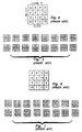
- Figure 4 is a 4 x 4 group-1 matrix. As shown in Figure 5, sixteen gray levels (plus all white) are obtained by sequentially increasing the number of sub-elements which are printed in black.
- Group-2 screen functions are known generally as "dot dispersion" type.
- the best known dot dispersion type screen functions were developed by Bayer, Lippel, and Jarvis.
- Figure 6 is typical a 4 x 4 group-2 matrix.
- sixteen gray levels (plus all white) are obtained by sequentially increasing the number of sub-elements which are printed.
- US-A-3 922 484 discloses a method of raster reproduction wherein, in response to increasing tone value steps, patterns are printed wherein at a lowest tone value a central area of a raster section is recorded with a minimal size dot. With increasing tone values, there is provided growth around the central area. At integral multiples of the lowest tone value, a dispersed growth pattern of dots is provided wherein each dot is a corresponding integral multiple of the smallest sized dot. However, further dispersion of dots ends while the tone values are still in the lower density range. In the higher density range increasing tone values causes growth by fattening of the dispersed dots.
- RCA Review, vol. 31, no.3, Klensch et al.: "Electronically Generated Halftone Pictures” discloses a halftone system wherein a halftone is represented by relatively large minimal dots using a coarse screen pattern. In the lightest highlight regions minimal dots are provided to define a screened density pattern. As density increases, new dots are added halfway between original dots and at highest density, dots increase uniformly in size.
- the sub-elements are dispersed in a manner to create a high spacial frequency so that the overlap of the sub-elements are minimal, whereas in a group-1 matrix, the sub-elements are grouped together so that there is greater overlap. Therefore the sub-elements of a group-1 matrix will cover less area than an equal number of sub-elements in a group-2 matrix.
- a document copying apparatus which generates a plurality of electrical image signals of successive picture elements of an original document includes: means for comparing input image signals representing low optical density picture elements to a series of threshold values selected from a two dimensional matrix halftone cell in which an output signal density pattern grows in a low spacial frequency manner; and means for comparing input image signals representing high optical density picture elements to a series of threshold values selected from a two dimensional matrix halftone cell in which an output signal density pattern grows in a high spacial frequency manner.
- Figure 8 is a comparison of the apparent density produced by group-1 and group-2 matrices as a function of the number of sub-elements which are printed. As can be seen from the figure, the slope of the group-1 matrix curve is greater in the high density portion of the curve, and the slope of the group-2 matrix curve is greater in the low density portion of the curve.
- group-1 matrices Since their density slopes are less in low density regions, group-1 matrices exhibit more observable density levels, and therefore less density contouring, at low densities than group-2 matrices because the group-2 matrix tone scale is compressed, resulting in rapid low density rise (high contrast). Accordingly, group-1 matrices would be preferred at low densities.
- group-2 matrices exhibit more observable density levels, and therefore less density contouring, at high densities than group-1 matrices because the type 1 matrix tone scale is compressed at these densities, resulting in rapid high density rise (high contrast). Accordingly, group-2 matrices would be preferred at high densities.
- the present invention provides for mixing group-1 and group-2 matrices so that a group-1 matrix is used in low density areas of the image and a group-2 matrix is used in high density areas of the image. Good results have been observed when the cut between group-1 and group-2 matrices have been made at density levels of between 60 and 80 on a 255 gray level scale.
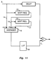
- Figure 9 is a schematic view of the electronic screening process for switching between group-1 and group-2 matrices according to the average density of an area.
- a scan line, designated (J-1) of the input signal X i is scanned, the electrical signals representing the density for each successive picture element along the scan line are stored in an analog shift register 12.
- the electrical signals from that line replace those of the preceding scan line in register 12, and the replaced signals are shifted into a second shift register 13.
- averager 15 of Figure 9 serially receives the electrical signals from scan lines (J+1), J, and (J-1), with all three inputs synchronized such that the corresponding samples from each scan line arrive simultaneously.
- Figure 10 depicts samples (J+1,K+1), (J+1,K), and (J+1,K-1) from scan line (J+1); samples (J,K+1), (J,K), and (J,K-1) from scan line J; and (J-1,K+1), (J-1,K), and (J-1,K-1) from scan line (J-1).
- a comparator 20 compares the averaged density signal from averager 15 with a reference threshold level determined on the basis of the density level selected for switching between group-1 and group-2 matrices.
- the output of comparator 20 is a logical zero which, when inverted and applied to an AND gate 22, causes the threshold level C i to be selected in sequential order from a two-dimensional group-1 matrix 24.
- the output of comparator 20 is a logical "ONE" which when applied to AND gate 22 causes the threshold level C i to be selected in sequential order from a two-dimensional group-2 matrix 28.
- Figure 8 which is not to scale, shows this graphically by plotting the apparent density verses the number of printed sub-elements for group-l and group-2 matrices.
- group-2 matrices the density rises quickly at low densities and has a lower slope at maximum densities.
- group-1 matrices the density rises more slowly at low densities and has a greater slope at maximum densities.
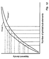
- Figure 12 there are illustrated in Figure 12, six different vertical lines representing different number of printed sub-elements.
- the intersections of the vertical lines with the density curves for group-1 and group-2 matrices are brought to the density scale where, going from bottom to top, eleven different densities are attainable by switching between matrices in the sequence 1,2,1,2,1,1 or 2,2,1,2,1,1.
- eleven different densities are attainable by switching between matrices in the sequence 1,2,1,2,1,1 or 2,2,1,2,1,1.
- it should be noted that as many as twelve different densities are theoretically possible, but it is at least possible that there will be overlap between a dot pattern of one matrix and a dot pattern of the other matrix, as is seen between the third vertical line of the group-2 matrix and the forth vertical line of the group-1 matrix.
- both groups are mixed in accordance with a look up table 30 of Figure 11.
- the input to the table is the average gray level value of a sample image picture elements.
- the look up table will provide an output indicating the number of sub-elements to be printed and the matrix to be used for that gray level value.
Landscapes
- Engineering & Computer Science (AREA)
- Multimedia (AREA)
- Signal Processing (AREA)
- Facsimile Image Signal Circuits (AREA)
- Image Processing (AREA)
Claims (9)
- Vorrichtung zum Herstellen einer Rasteraufnahme von einem Originalbild, mit
Mitteln (12, 13, 15) zum Erzeugen einer Reihe von Eingangsbildsignalwerten, die die Tonwerte von Bildelementen des Originalbildes darstellen,
einer Einrichtung (24) zum Erzeugen einer ersten Reihe unterschiedlicher Schwellenwerte von einer ersten Matrix mit einer Vielzahl von Unterelementen mit einem Schwellenwertmuster, das um einen Kern herum wächst und die erste Reihe von Schwellenwerten bildet,
einer Einrichtung (28) zum Erzeugen einer zweiten Reihe unterschiedlicher Schwellenwerte von einer zweiten Matrix mit einer Vielzahl von Unterelementen mit einem Schwellenwertmuster, das in einer hohen Raumfrequenz wächst und die zweite Reihe von Schwellenwerten bildet,
gekennzeichnet durch Mittel (22; 30) zum Vergleichen zugeordneter Eingangsbildsignalwerte der jeweiligen Bildelemente mit jeweils unterschiedlichen Schwellenwerten der ersten Matrix, wenn sich die Bildelemente im niedrigsten optischen Dichtebereich befinden,
Mittel (26; 30) zum Vergleichen zugeordneter Eingangsbildsignale der jeweiligen Bildelemente der Gruppe mit jeweils unterschiedlichen Schwellenwerten der zweiten Matrix, wenn sich die Bildelemente im höchsten optischen Dichtebereich befinden, und
auf die Vergleichsmittel reagierende Mittel zum Erzeugen von Ausgangssignalen, die ein Bild mit einem Ausgangsdichtemuster darstellen, das auf niederfrequente Weise wächst, wenn Schwellenwerte der ersten Matrix verwendet werden, und zum Abgeben von Signalen, die ein Ausgangsdichtemuster haben, das auf hochfrequente Weise wächst, wenn Schwellenwerte der zweiten Matrix verwendet werden. - Vorrichtung nach Anspruch 1, dadurch gekennzeichnet, daß gedruckte Unterelemente einer Matrix-Rasterzelle, in der ein Ausgangsdichtemuster auf niederfrequente Weise wächst, um einen Kern herum wachsen.
- Vorrichtung nach Anspruch 1, dadurch gekennzeichnet, daß gedruckte Unterelemente einer Matrix-Rasterzelle, in der ein Ausgangsdichtemuster auf niederfrequente Weise wächst, um einen mittig zur Zelle angeordneten Kern herum wachsen.
- Vorrichtung nach Anspruch 1, 2 oder 3, gekennzeichnet durch eine Einrichtung (15) zum Mitteln der optischen Dichte von Bildelementen in Bereichen einer Originalvorlage.
- Vorrichtung nach Anspruch 1, 2, 3 oder 4, dadurch gekennzeichnet, daß der Bereich geringster Dichte optischen Dichtewerten von unter 60 auf einer 256 Grauwertskala entspricht.
- Vorrichtung nach Anspruch 1, 2, 3 oder 4, dadurch gekennzeichnet, daß der Bereich geringster Dichte optischen Dichtewerten von unter 80 auf einer 256 Grauwertskala entspricht.
- Vorrichtung nach Anspruch 1 bis 6, gekennzeichnet durch eine Einrichtung (30), die Eingangsbildsignale, welche Bildelemente der Originalvorlage in einem mittleren optischen Dichtebereich darstellen, mit einer Reihe von Schwellenwerten vergleicht, die gemäß der optischen Dichte des Bildelements der Reihe nach aus der ersten (24) oder der zweiten Matrix (28) ausgewählt werden.
- Vorrichtung nach Anspruch 1 bis 7, dadurch gekennzeichnet, daß die auf die Vergleichsmittel reagierende Einrichtung Ausgangssignale erzeugt, von denen jedes eine von einem von zwei Druckwerten gekennzeichnete Entscheidung "drucken" oder "nicht drucken" darstellt.
- Vorrichtung nach Anspruch 1, dadurch gekennzeichnet, daß ein Eingangssignal X₁ die Helligkeits- oder Grauwertinformationen an einem Abtastpunkt i eines Bildes darstellt, daß die Eingangssignale X₁ der Bildelemente des abgetasteten Bildes mit einer Reihe von Schwellenwerten C₁ verglichen werden, die in einer Reihenfolge aus einer zweidimensionalen, als Rasterschwellensatz definierten Matrix ausgewählt werden, und die Ausgangssignale eine Entscheidung "drucken"/"nicht drucken" darstellen, und daß die Reihen von Schwellenwerten und ihre Anordnung innerhalb des Schwellenwertsatzes den Grauwertbereich, die Frequenz, den Winkel und andere Eigenschaften eines Rasterbildes bestimmen, wobei jeder Schwellenwertpegel C₁ bestimmt ist durch eine j x k Vergleichsmatrix und wobei das entsprechende Unterelement, wenn das Eingangssignal X₁ den Schwellenwertpegel C₁ übersteigt, einen Logikpegel mit der Entscheidung "drucken" hat, so daß bei einem Vergleich der Eingangssignale X₁ mit den Schwellenwertpegeln j x k Ausgangssignale O₁ erzeugt werden und ein Dichtemuster aus einer Kombination von j x k Unterelementen gebildet wird, wobei die j x k Unterelemente systematisch gedruckt oder frei gelassen werden.
Applications Claiming Priority (3)
| Application Number | Priority Date | Filing Date | Title |
|---|---|---|---|
| US45079589A | 1989-12-14 | 1989-12-14 | |
| US450795 | 1989-12-14 | ||
| PCT/US1990/007037 WO1991009489A2 (en) | 1989-12-14 | 1990-12-03 | Mixed matrix image processing for rendering halftone images with variable dot sizes |
Publications (2)
| Publication Number | Publication Date |
|---|---|
| EP0458966A1 EP0458966A1 (de) | 1991-12-04 |
| EP0458966B1 true EP0458966B1 (de) | 1995-07-19 |
Family
ID=23789514
Family Applications (1)
| Application Number | Title | Priority Date | Filing Date |
|---|---|---|---|
| EP91907200A Expired - Lifetime EP0458966B1 (de) | 1989-12-14 | 1990-12-03 | Gemischte matrix-bildverarbeitung zur wiedergabe von halbtonbildern mit veränderlicher punktgrösse |
Country Status (4)
| Country | Link |
|---|---|
| EP (1) | EP0458966B1 (de) |
| JP (1) | JPH04504797A (de) |
| DE (1) | DE69021046T2 (de) |
| WO (1) | WO1991009489A2 (de) |
Families Citing this family (4)
| Publication number | Priority date | Publication date | Assignee | Title |
|---|---|---|---|---|
| US5291311A (en) * | 1992-06-29 | 1994-03-01 | Eastman Kodak Company | Apparatus and method for generating multi-level output values for pixels in a halftone cell |
| TW305951B (de) * | 1995-02-27 | 1997-05-21 | Toray Industries | |
| US5911009A (en) * | 1996-01-25 | 1999-06-08 | Dainippon Screen Mfg. Co., Ltd. | Method and apparatus for binary coding of image data including adding error accumulated for a target pixel and a pixel in the vicinity to be later coded |
| JP5038763B2 (ja) | 2006-04-04 | 2012-10-03 | 株式会社リコー | インクジェット記録装置と画像処理方法、画像処理制御プログラムと記録媒体および高浸透性顔料インク |
Family Cites Families (4)
| Publication number | Priority date | Publication date | Assignee | Title |
|---|---|---|---|---|
| DE2262824C3 (de) * | 1972-12-22 | 1975-07-10 | Dr.-Ing. Rudolf Hell Gmbh, 2300 Kiel | Verfahren zur gerasterten Reproduktion farbiger Halbtonbilder im Ein- oder Mehrfarbendruck |
| US4449150A (en) * | 1981-01-19 | 1984-05-15 | Ricoh Company, Ltd. | Method of processing medium tone picture |
| EP0126782B1 (de) * | 1983-05-02 | 1987-09-16 | Ibm Deutschland Gmbh | Verfahren für die Bildwiedergabe mit Grauwerten |
| EP0248616A3 (de) * | 1986-06-02 | 1990-03-07 | Kabushiki Kaisha Toshiba | Bilddruckgerät |
-
1990
- 1990-12-03 WO PCT/US1990/007037 patent/WO1991009489A2/en not_active Ceased
- 1990-12-03 JP JP91507975A patent/JPH04504797A/ja active Pending
- 1990-12-03 EP EP91907200A patent/EP0458966B1/de not_active Expired - Lifetime
- 1990-12-03 DE DE69021046T patent/DE69021046T2/de not_active Expired - Lifetime
Also Published As
| Publication number | Publication date |
|---|---|
| WO1991009489A3 (en) | 1991-08-22 |
| DE69021046D1 (de) | 1995-08-24 |
| WO1991009489A2 (en) | 1991-06-27 |
| JPH04504797A (ja) | 1992-08-20 |
| DE69021046T2 (de) | 1996-02-29 |
| EP0458966A1 (de) | 1991-12-04 |
Similar Documents
| Publication | Publication Date | Title |
|---|---|---|
| US5200831A (en) | Method and arrangement for locally switching gray dot types to reproduce an image with gray level printing | |
| US6775032B2 (en) | Apparatus and method for halftone hybrid screen generation | |
| US5694224A (en) | Method and apparatus for tone adjustment correction on rendering gray level image data | |
| DE69521381T2 (de) | Fehlerdiffusionhalbtonrasterung mit homogener Ausgabe in Bildbereichen hoher/niedriger Intensität | |
| US5729632A (en) | Reproduction apparatus and method for adjusting rendering with toners of different particle sizes | |
| US4668995A (en) | System for reproducing mixed images | |
| US5625460A (en) | Method and apparatus for locally switching gray dot types to reproduce an image with gray level printing | |
| US5107349A (en) | Multiple screen frequency half-toning with one screen angle | |
| DE69309409T2 (de) | Gruppierte Halbtönung mit Punkt-zu-Punkt-Fehlerdiffusion | |
| US5325211A (en) | Error diffusion with output and input based feedback | |
| US5956157A (en) | Method and apparatus for locally blending gray dot types of the same or different types to reproduce an image with gray level printing | |
| US6285464B1 (en) | Apparatus and method for producing a half-tone image | |
| US5239390A (en) | Image processing method to remove halftone screens | |
| US5258850A (en) | Line screen design for gray scale rendering | |
| US5313309A (en) | Method and apparatus for printing halftones with a gray level printer with contour suppression and/or minimization of moire patterns | |
| US5258849A (en) | Halftone dot arrangement in gray level halftone printing | |
| US5204753A (en) | Multi-bit rendering method and arrangement for continuous tone picture representation and printing | |
| US7262879B2 (en) | Method for screening of halftone images | |
| US5598204A (en) | Image halftoning system capable of producing additional gradations | |
| US5198910A (en) | Mixed matrix image processing for rendering halftone images with variable dot sizes | |
| EP0461250B1 (de) | Fehlerhafte dichtekonturunterdrückung, die zufallsmodifizierte eingangssignale für den vergleich mit schwellenwerten benutzt | |
| US6002493A (en) | Method for reproducing an image | |
| US5359431A (en) | Classification to change exposure within a cell of different pixels | |
| US20040090654A1 (en) | FM screening with sub-dot phase modulation | |
| US6141121A (en) | Method and apparatus for color halftoning |
Legal Events
| Date | Code | Title | Description |
|---|---|---|---|
| PUAI | Public reference made under article 153(3) epc to a published international application that has entered the european phase |
Free format text: ORIGINAL CODE: 0009012 |
|
| AK | Designated contracting states |
Kind code of ref document: A1 Designated state(s): DE FR GB |
|
| 17P | Request for examination filed |
Effective date: 19911202 |
|
| 17Q | First examination report despatched |
Effective date: 19940217 |
|
| GRAA | (expected) grant |
Free format text: ORIGINAL CODE: 0009210 |
|
| AK | Designated contracting states |
Kind code of ref document: B1 Designated state(s): DE FR GB |
|
| REF | Corresponds to: |
Ref document number: 69021046 Country of ref document: DE Date of ref document: 19950824 |
|
| ET | Fr: translation filed | ||
| PLBE | No opposition filed within time limit |
Free format text: ORIGINAL CODE: 0009261 |
|
| STAA | Information on the status of an ep patent application or granted ep patent |
Free format text: STATUS: NO OPPOSITION FILED WITHIN TIME LIMIT |
|
| 26N | No opposition filed | ||
| REG | Reference to a national code |
Ref country code: GB Ref legal event code: 732E |
|
| REG | Reference to a national code |
Ref country code: GB Ref legal event code: IF02 |
|
| REG | Reference to a national code |
Ref country code: GB Ref legal event code: 732E |
|
| PGFP | Annual fee paid to national office [announced via postgrant information from national office to epo] |
Ref country code: GB Payment date: 20061106 Year of fee payment: 17 |
|
| PGFP | Annual fee paid to national office [announced via postgrant information from national office to epo] |
Ref country code: FR Payment date: 20061201 Year of fee payment: 17 |
|
| GBPC | Gb: european patent ceased through non-payment of renewal fee |
Effective date: 20071203 |
|
| REG | Reference to a national code |
Ref country code: FR Ref legal event code: ST Effective date: 20081020 |
|
| PG25 | Lapsed in a contracting state [announced via postgrant information from national office to epo] |
Ref country code: GB Free format text: LAPSE BECAUSE OF NON-PAYMENT OF DUE FEES Effective date: 20071203 |
|
| PG25 | Lapsed in a contracting state [announced via postgrant information from national office to epo] |
Ref country code: FR Free format text: LAPSE BECAUSE OF NON-PAYMENT OF DUE FEES Effective date: 20071231 |
|
| PGFP | Annual fee paid to national office [announced via postgrant information from national office to epo] |
Ref country code: DE Payment date: 20091230 Year of fee payment: 20 |
|
| PG25 | Lapsed in a contracting state [announced via postgrant information from national office to epo] |
Ref country code: DE Free format text: LAPSE BECAUSE OF EXPIRATION OF PROTECTION Effective date: 20101203 |