EP0458992B2 - Dispositif de pulvérisation de liquide de sel à dégeler immobile pour chaussées et aéroports - Google Patents
Dispositif de pulvérisation de liquide de sel à dégeler immobile pour chaussées et aéroports Download PDFInfo
- Publication number
- EP0458992B2 EP0458992B2 EP90110003A EP90110003A EP0458992B2 EP 0458992 B2 EP0458992 B2 EP 0458992B2 EP 90110003 A EP90110003 A EP 90110003A EP 90110003 A EP90110003 A EP 90110003A EP 0458992 B2 EP0458992 B2 EP 0458992B2
- Authority
- EP
- European Patent Office
- Prior art keywords
- conduit
- deicing
- deicing medium
- storage means
- hydraulic storage
- Prior art date
- Legal status (The legal status is an assumption and is not a legal conclusion. Google has not performed a legal analysis and makes no representation as to the accuracy of the status listed.)
- Expired - Lifetime
Links
Images

Classifications
-
- B—PERFORMING OPERATIONS; TRANSPORTING
- B05—SPRAYING OR ATOMISING IN GENERAL; APPLYING FLUENT MATERIALS TO SURFACES, IN GENERAL
- B05B—SPRAYING APPARATUS; ATOMISING APPARATUS; NOZZLES
- B05B9/00—Spraying apparatus for discharge of liquids or other fluent material, without essentially mixing with gas or vapour
- B05B9/03—Spraying apparatus for discharge of liquids or other fluent material, without essentially mixing with gas or vapour characterised by means for supplying liquid or other fluent material
- B05B9/04—Spraying apparatus for discharge of liquids or other fluent material, without essentially mixing with gas or vapour characterised by means for supplying liquid or other fluent material with pressurised or compressible container; with pump
- B05B9/047—Spraying apparatus for discharge of liquids or other fluent material, without essentially mixing with gas or vapour characterised by means for supplying liquid or other fluent material with pressurised or compressible container; with pump supply being effected by follower in container, e.g. membrane or floating piston, or by deformation of container
-
- E—FIXED CONSTRUCTIONS
- E01—CONSTRUCTION OF ROADS, RAILWAYS, OR BRIDGES
- E01H—STREET CLEANING; CLEANING OF PERMANENT WAYS; CLEANING BEACHES; DISPERSING OR PREVENTING FOG IN GENERAL CLEANING STREET OR RAILWAY FURNITURE OR TUNNEL WALLS
- E01H10/00—Improving gripping of ice-bound or other slippery traffic surfaces, e.g. using gritting or thawing materials ; Roadside storage of gritting or solid thawing materials; Permanently installed devices for applying gritting or thawing materials; Mobile apparatus specially adapted for treating wintry roads by applying liquid, semi-liquid or granular materials
- E01H10/005—Permanently-installed devices for applying gritting or thawing materials, e.g. for spreading grit, for spraying de-icing liquids
Definitions
- the invention relates to a stationary deicing agent spraying device according to the preamble of claim 1.
- Such devices are known and are e.g. used for bridges and viaducts, tunnel entrances and exits, other particularly ice-free highway sections, as well as taxiways and airport runways.
- the de-icing agent is guided to the individual spray nozzles through a pressure line line arranged along the roadway or slope.
- the number of spray nozzles varies depending on the system, but the de-icing agent usually has to be pumped over several hundred meters or several kilometers. To ensure that the pressure drop along the line does not become too great and to supply the spray nozzles in the end area of the line with sufficient pressure, lines with a large internal diameter are necessary for the line string. This is disadvantageous for several reasons.
- the line is expensive per se and it is also too expensive to lay it on the ground or on the road, particularly with regard to compensating for the change in length in the event of temperature variation.
- the cables are therefore routed above ground next to the road. This increases the risk of damage to the line, especially in the event of an accident on the road. In the event of damage, such a large line also releases large amounts of de-icing agent, which is to be avoided for environmental reasons and can also lead to subsequent accidents on the road.
- the amount of de-icing agent sprayed per nozzle is metered via the spraying time; a more precise, volumetric dosage of the de-icing agent would be desirable.
- the invention is therefore based on the object of creating a de-icing spray device which avoids the disadvantages mentioned.
- the plurality of hydraulic accumulators each with its own non-return valve, which stores de-icing agents along the pipeline or the web along with the pressure of the pipeline and from which the nozzles are fed, results in the following advantages: Since the pipeline only for filling the accumulator is used, for which sufficient time is available, small cable diameters can be used; this makes it possible to lay the wiring harness in the ground at low cost. The pump delivery rate can be reduced. Since a defined amount of de-icing agent is stored in the individual hydraulic accumulators, it can be dosed on a quantity basis and not on a time basis. With the hydraulic accumulators, the de-icing agent can be applied as before by successively actuating the spray nozzle. The hydraulic accumulators also offer the option of activating a large number of spray nozzles at the same time.
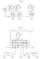
- the de-icing agent spray device shown schematically as an example is divided into three spray sections A, B and C, each 600 meters long. Each section A, B, C has a line 4 for the de-icing agent along each lane 1, 2. This is carried out in a generally known manner from de-icing tanks 5 via a line network 7 by means of pumps 6 to the respective line section 4, various controllable valves, pressure monitors etc. making it possible to influence, monitor and display the status of the device in a manner known per se.
- the device is controlled in a manner which is also fundamentally known by means of a program-controlled one electronic control. It was known in such devices to connect individual spray nozzles to the line 4 each via a valve (not shown) which can be activated by the control and in this way to spray the de-icing agent for a predetermined time.
- a plurality of hydraulic accumulators 10 are now connected to line 4 via a check valve 11.
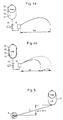
- a hydraulic accumulator is a known element for storing hydraulic energy (see e.g. Lueger Lexikon dertechnik, Stuttgart 1967, Vol. 8, page 466). Hydropneumatic pressure accumulators with a separation 12 between a gas space 13 and the liquid space 14 are used. The hydraulic accumulators are fed through the pressure line 4 until an equilibrium between the gas bubble pressure and the static liquid pressure, caused by the pump 6, is reached in each accumulator. The line diameter of line 4 plays no role in achieving the static pressure equilibrium.
- the pressure accumulator 10 which is furthest away from the pump 6 also stores practically the same hydraulic energy as the accumulators 10 located closer to the pump 10.
- the spray nozzles 16 are fed from the accumulators 10 via controllable valves 15, as will be explained in more detail later.
- the pressure accumulators 10 allow the use of pipes with a small inner diameter for the line 4, e.g. of plastic pressure pipes with an inner diameter of 25 mm. Furthermore, since constrictions in connections etc. are irrelevant for the static pressure distribution, the expansion compensation elements required for such long pipelines 4 made of plastic pressure pipes can simply be implemented as hose loops connected between two pipe sections. The possibilities for the dimensioning of the lines given by the pressure accumulators 10 enable them to be laid in the ground with reasonable effort.
- the pressure accumulator 10 can be explained on the basis of the same figures.
- the stored amount of de-icing agent is known; e.g. a hydraulic accumulator 10 is used, the volume of the liquid space 14 in the loaded state (FIG. 4a) is 1 liter.
- the amount of de-icing agent applied is precisely known, namely 1 liter.
- FIG. 5 Another advantage can be explained with reference to FIG. 5.
- the situation of an ascending roadway or a correspondingly ascending line 4 is shown there.
- the pump pressure is again 8 bar, there is a static pressure of 7 bar (8 bar - 1 bar) at the end of the line for filling the store with a height difference delta H of 10 meters up to the store 10 shown.
- the gas pressure for the accumulator 10 is chosen so that the equilibrium position is established at 7 bar gas or liquid pressure, the liquid space having a volume of 1 liter. This compensation of the pressure loss on slopes makes it easier to arrange the pump on the lower part of a slope.
- FIG. 1 shows storage and valve cabinets 20 connected to the pressure line 4. Such a cupboard is located close to the carriageway (above or below ground) at a distance of 80 meters.
- Fig. 3 shows schematically the structure of such a cabinet 20.
- a branch of the preferably underground line 4 is guided in this.
- a distribution channel 21 is connected to the line via a check valve 11, which holds the storage charge even when the line pressure is lost.
- the memory 10 is connected to this channel 21 and can thus be fed from the line 4.
- the controllable valves 15 are connected to the distribution channel 21, each of which connects a spray head 16 (with one or more spray nozzles) to the accumulator in order to carry out the spraying process.
- the well-known control for the valves is not shown.
- valves per cabinet are shown. Since a cabinet is arranged every 80 meters, this results in an arrangement of 5 spray heads for each 80 meter street or one spray head for 16 meters street length.
- the device is controlled by an electronic black ice early warning system (GFS), so that the de-icing agent is switched on automatically in the event of danger and completes a program adapted to the use of pressure accumulators.
- GFS black ice early warning system
- the GFS system provides a precise overview of the status of the monitored routes and allows the device to be operated manually over longer distances (e.g. 20 km) from the location of the GFS screens.
- Activating a valve 15 in the valve cabinet or spraying through the spray nozzle takes place e.g. for 1 second.
- the liquid space 14 of the pressure accumulator 10 is emptied i.e. 1 liter of de-icing agent is sprayed.
- Spray heights of 40 cm and spray widths of up to 10 m are achieved with the spray nozzles.
- the accumulator 10 is recharged via the line 4.
- the filling time varies depending on the location of the memory. In practice it has been shown that a filling time of approximately 5 seconds to 15 seconds can be expected until a reservoir 10 is filled again with 1 liter of de-icing agent. After this filling time, the next valve 15 in the cabinet can be activated and another spray is carried out for one second.
- the prior art devices were sprayed sequentially, i.e. only one spray nozzle was active on each line strand 4 at the same time. Another nozzle was only activated when this nozzle was deactivated.
- the device according to the invention can also be operated in this way: First, for each section A, B, C, the first of the five valves 15 in the first cabinet is actuated for one second; then the first valve of the five valves in the second cabinet; then the first of the five valves in the third cabinet, etc., up to the first valve in the nth cabinet, then the second of the five valves of the first cabinet is activated and the de-icing medium content of the pressure reservoir of the first cabinet, which has meanwhile been refilled, is sprayed; the second valve of the second cabinet follows, etc.
- the device according to the invention now also enables a new mode of operation. Thanks to the hydraulic accumulator 10, several or all of the cabinets can be activated at the same time, i.e. At the same time, one of the valves, e.g. the first valve of the five valves 15 per cabinet are activated. This is only possible since, in the device according to the invention, each cupboard has a pressurized de-icing agent storage container, the store 10. With this mode of operation, extensive spraying of the web can be achieved very quickly, which e.g. may be desirable at airports.
Landscapes
- Engineering & Computer Science (AREA)
- Architecture (AREA)
- Civil Engineering (AREA)
- Structural Engineering (AREA)
- Application Of Or Painting With Fluid Materials (AREA)
- Materials Applied To Surfaces To Minimize Adherence Of Mist Or Water (AREA)
- Road Paving Structures (AREA)
- Agricultural Chemicals And Associated Chemicals (AREA)
- Nozzles (AREA)
- Road Paving Machines (AREA)
Claims (7)
- Installation stationnaire de pulvérisation d'un agent de déverglaçage pour routes, pistes de roulage et pistes de décollage et d'atterrissage, comprenant une station de pompage comportant au moins une pompe pour agent de déverglaçage (6) et au moins un réservoir pour agent de déverglaçage (5), un système de canalisations (7) pour l'agent de déverglaçage alimenté par la pompe (6) comportant au moins une canalisation (4) qui suit la chaussée, un grand nombre de pulvérisateurs (16) qui peuvent être alimentés en agent de déverglaçage par l'intermédiaire de la canalisation (4) et d'un dispositif de valves pouvant être commandé pour amener l'agent de déverglaçage sur la surface de la chaussée et une unité de commande électronique commandée par programme pour la station de pompage, et le dispositif de valves, par laquelle les valves du dispositif de valves peuvent être activées individuellement, sachant qu'à la canalisation (4) sont raccordés de nombreux accumulateurs hydrauliques (10) chaque fois associés à un pulvérisateur (16) ou à un groupe de pulvérisateurs (16) qui peuvent être alimentés en agent de déverglaçage à partir de la canalisation, lesdits accumulateurs hydrauliques (10) étant des accumulateurs hydropneumatiques pourvus d'une membrane de séparation (12) et pouvant être raccordés au pulvérisateur (16) ou bien au groupe de pulvérisateurs par le biais du dispositif de valves (15), lors de la mise en circulation de l'agent de déverglaçage, caractérisée en ce que chaque accumulateur hydraulique individuel est raccordé à la canalisation (4) par l'intermédiaire d'une valve antiretour (11) qui lui est propre.
- Installation de pulvérisation d'agent de déverglaçage suivant la revendication 1, caractérisée en ce que l'accumulateur hydraulique (10) et la valve antiretour (11) sont chaque fois raccordés à un organe de répartition, auquel un certain nombre de valves pouvant être commandées (15) du dispositif de valves sont raccordées.
- Installation de pulvérisation d'agent de déverglaçage suivant la revendication 2, caractérisée en ce que la canalisation (4) s'étend en substance sous le niveau de la chaussée, et que l'accumulateur hydraulique, la valve antiretour, l'organe de répartition et les valves sont disposés dans une chambre commune.
- Installation de pulvérisation d'agent de déverglaçage suivant l'une des revendications 1 à 3, caractérisée en ce que la canalisation est en substance constituée de tubes en matière plastique résistant à la pression, des éléments de tuyau souples étant prévus dans la canalisation pour compenser la dilatation.
- Installation de pulvérisation d'agent de déverglaçage suivant l'une quelconque des revendications 1 à 4, caractérisée en ce que plusieurs valves antiretour sont prévues le long de la canalisation.
- Procédé de mise en oeuvre d'une installation de pulvérisation d'agent de déverglaçage suivant l'une quelconque des revendications précédentes, caractérisé en ce que la pression de gaz dans chaque accumulateur hydraulique (10) est choisie telle qu'en substance, la même quantité d'agent de déverglaçage soit accumulée dans chaque accumulateur hydraulique (10).
- Procédé suivant la revendication 6, caractérisé en ce que, lors du processus de pulvérisation, chaque fois plusieurs accumulateurs hydrauliques (10) sont vidés simultanément.
Priority Applications (4)
| Application Number | Priority Date | Filing Date | Title |
|---|---|---|---|
| DK90110003.2T DK0458992T3 (da) | 1990-05-26 | 1990-05-26 | Stationært optøningsmiddelsprøjteapparat til veje og lufthavne |
| DE90110003T DE59002576D1 (de) | 1990-05-26 | 1990-05-26 | Stationäre Taumittelsprüheinrichtung für Strassenfahrbahnen und Flugplätze. |
| AT90110003T ATE93917T1 (de) | 1990-05-26 | 1990-05-26 | Stationaere taumittelsprueheinrichtung fuer strassenfahrbahnen und flugplaetze. |
| EP90110003A EP0458992B2 (fr) | 1990-05-26 | 1990-05-26 | Dispositif de pulvérisation de liquide de sel à dégeler immobile pour chaussées et aéroports |
Applications Claiming Priority (1)
| Application Number | Priority Date | Filing Date | Title |
|---|---|---|---|
| EP90110003A EP0458992B2 (fr) | 1990-05-26 | 1990-05-26 | Dispositif de pulvérisation de liquide de sel à dégeler immobile pour chaussées et aéroports |
Publications (3)
| Publication Number | Publication Date |
|---|---|
| EP0458992A1 EP0458992A1 (fr) | 1991-12-04 |
| EP0458992B1 EP0458992B1 (fr) | 1993-09-01 |
| EP0458992B2 true EP0458992B2 (fr) | 1996-10-16 |
Family
ID=8204029
Family Applications (1)
| Application Number | Title | Priority Date | Filing Date |
|---|---|---|---|
| EP90110003A Expired - Lifetime EP0458992B2 (fr) | 1990-05-26 | 1990-05-26 | Dispositif de pulvérisation de liquide de sel à dégeler immobile pour chaussées et aéroports |
Country Status (4)
| Country | Link |
|---|---|
| EP (1) | EP0458992B2 (fr) |
| AT (1) | ATE93917T1 (fr) |
| DE (1) | DE59002576D1 (fr) |
| DK (1) | DK0458992T3 (fr) |
Families Citing this family (7)
| Publication number | Priority date | Publication date | Assignee | Title |
|---|---|---|---|---|
| FR2729166A1 (fr) * | 1995-01-05 | 1996-07-12 | Lamy Perret Emile | Systeme d'arrosage automatise avec electrovannes |
| DK0947633T3 (da) | 1998-03-20 | 2000-09-25 | Fribair Sa | Fremgangsmåde og indretning til udspredning af flydende optøningsmidler |
| CZ300601B6 (cs) * | 1998-03-20 | 2009-06-24 | Fribair S. A. | Zpusob nanášení kapalného rozmrazovacího prostredku a rozstrikovací zarízení |
| DE10260934A1 (de) * | 2002-12-20 | 2004-07-01 | Andreas Leonhard | Streuanlage für Treppen, Gehwege odgl. zur Unterbindung von Glatteisrutschen |
| US7798432B2 (en) | 2008-03-25 | 2010-09-21 | Envirotech Services, Inc. | Device for spraying anti-icing agents on transport surface |
| WO2013121591A1 (fr) * | 2012-02-13 | 2013-08-22 | 北海道日油株式会社 | Dispositif d'alimentation en agent antigel liquide et procédé d'alimentation en agent antigel liquide |
| CA3016927C (fr) | 2017-09-08 | 2025-01-07 | F. Von Langsdorff Licensing Limited | Systeme de pavement integre servant a collecter et recycler du fluide de degivrage |
Family Cites Families (2)
| Publication number | Priority date | Publication date | Assignee | Title |
|---|---|---|---|---|
| US3403818A (en) * | 1966-09-30 | 1968-10-01 | Binks Res And Dev Corp | Portable airless sprayer |
| CH658411A5 (de) * | 1982-09-10 | 1986-11-14 | Boschung Mecatronic Ag | Elektromagnetisch steuerbares und kontrollierbares spruehventil fuer fluessigkeiten und anlage mit derartigen spruehventilen. |
-
1990
- 1990-05-26 AT AT90110003T patent/ATE93917T1/de not_active IP Right Cessation
- 1990-05-26 DK DK90110003.2T patent/DK0458992T3/da active
- 1990-05-26 DE DE90110003T patent/DE59002576D1/de not_active Expired - Lifetime
- 1990-05-26 EP EP90110003A patent/EP0458992B2/fr not_active Expired - Lifetime
Also Published As
| Publication number | Publication date |
|---|---|
| DK0458992T3 (da) | 1993-11-22 |
| EP0458992B1 (fr) | 1993-09-01 |
| DE59002576D1 (de) | 1993-10-07 |
| ATE93917T1 (de) | 1993-09-15 |
| EP0458992A1 (fr) | 1991-12-04 |
Similar Documents
| Publication | Publication Date | Title |
|---|---|---|
| EP3995217B1 (fr) | Dispositif pour appliquer des adhésifs à plusieurs composants sur un mélange granulaire, ainsi que procédé d'application et utilisation du dispositif | |
| DE19647160C5 (de) | Verfahren und Vorrichtung für Halbschildvortrieb | |
| EP3523057B1 (fr) | Dispositif et procédé pour agglomérer la poussière | |
| DE2842258A1 (de) | Verfahren und vorrichtung zur abgabe eines betriebsstoffes, insbesondere eines schmiermaterials | |
| EP0458992B2 (fr) | Dispositif de pulvérisation de liquide de sel à dégeler immobile pour chaussées et aéroports | |
| WO2017102059A1 (fr) | Station-service dotée d'un réservoir de stockage à pression constante | |
| WO2018065586A1 (fr) | Dispositif et procédé pour agglomérer la poussière | |
| EP0947633B1 (fr) | Procédé et dispositif stationnaire de distribution de solution de sel à dégel | |
| AT519211A2 (de) | Entstaubungsvorrichtung | |
| EP1729981A1 (fr) | Dispositif de sablage pour des vehicules sur rails | |
| DE202021004316U1 (de) | Einrichtung zum Austragen von Einkomponenten- oder Mehrkomponentenklebstoff auf ein körniges Gemenge | |
| DE69306955T2 (de) | Versenkbare und versteckbare kraftstoffabgabevorrichtung | |
| EP0461295B1 (fr) | Tête d'atomiseur pour un dispositif de pulvérisation de liquide de sel à dégeler immobile pour chaussées et pour pistes de roulage, d'atterrissage et d'envol | |
| DE4216628A1 (de) | Entwässerungsanlage | |
| DE69003982T2 (de) | Anlage zum Befüllen von Fahrzeugen mit Erdölprodukten. | |
| DE69032272T2 (de) | Verfahren und vorrichtung zur farbeisolierung für elektrostatische beschichtung | |
| EP4037949B1 (fr) | Dispositif pour introduire du sable, véhicule ferroviaire, et procédé pour faire fonctionner un dispositif pour introduire du sable | |
| AT519212B1 (de) | Vorrichtung und Verfahren zum Binden von Staub | |
| DD283432A5 (de) | Einrichtung zum verkleben eines, insbesondere aus y-schwellen und schienen gebildeten gleisrostes auf beton-gleisunterbau | |
| DE19639425C2 (de) | Nachträgliche grabenlose Flugplatzbefeuerung | |
| DE19604379A1 (de) | Verfahren und Anlage zur Herstellung gebrauchsfertiger HFA-Flüssigkeiten | |
| DE20314091U1 (de) | Stationäre Schmiermittelvorrichtung zum Aufbringen eines Schmiermittels an Schienen, die von gleisgebundenen Fahrzeugen befahrbar sind | |
| DE4439882A1 (de) | Verfahren und Vorrichtung zur Versorgung von Sprinkleranlagen in hohen Wohn- und/oder Bürogebäuden mit Löschflüssigkeit | |
| DE10010249A1 (de) | Sprühsystem für eine Salzteststraße | |
| DE3837033A1 (de) | System fuer die kuenstliche be- und entwaesserung einer vegetationsschicht |
Legal Events
| Date | Code | Title | Description |
|---|---|---|---|
| REG | Reference to a national code |
Ref country code: DK Ref legal event code: T4 |
|
| PUAI | Public reference made under article 153(3) epc to a published international application that has entered the european phase |
Free format text: ORIGINAL CODE: 0009012 |
|
| AK | Designated contracting states |
Kind code of ref document: A1 Designated state(s): AT BE CH DE DK ES FR GB GR IT LI LU NL SE |
|
| RBV | Designated contracting states (corrected) |
Designated state(s): AT BE CH DE DK FR GB IT LI LU NL SE |
|
| 17P | Request for examination filed |
Effective date: 19920121 |
|
| 17Q | First examination report despatched |
Effective date: 19930129 |
|
| GRAA | (expected) grant |
Free format text: ORIGINAL CODE: 0009210 |
|
| AK | Designated contracting states |
Kind code of ref document: B1 Designated state(s): AT BE CH DE DK FR GB IT LI LU NL SE |
|
| REF | Corresponds to: |
Ref document number: 93917 Country of ref document: AT Date of ref document: 19930915 Kind code of ref document: T |
|
| ITF | It: translation for a ep patent filed | ||
| REF | Corresponds to: |
Ref document number: 59002576 Country of ref document: DE Date of ref document: 19931007 |
|
| GBT | Gb: translation of ep patent filed (gb section 77(6)(a)/1977) |
Effective date: 19930921 |
|
| ET | Fr: translation filed | ||
| REG | Reference to a national code |
Ref country code: DK Ref legal event code: T3 |
|
| PLBI | Opposition filed |
Free format text: ORIGINAL CODE: 0009260 |
|
| 26 | Opposition filed |
Opponent name: NIDO -UNIVERSAL MACHINES BV Effective date: 19940531 Opponent name: SCHUH & CO. GMBH Effective date: 19940531 |
|
| EPTA | Lu: last paid annual fee | ||
| NLR1 | Nl: opposition has been filed with the epo |
Opponent name: SCHUH & CO. GMBH Opponent name: NIDO -UBIVERSAL MACHINES BV |
|
| EAL | Se: european patent in force in sweden |
Ref document number: 90110003.2 |
|
| PLAW | Interlocutory decision in opposition |
Free format text: ORIGINAL CODE: EPIDOS IDOP |
|
| PLAW | Interlocutory decision in opposition |
Free format text: ORIGINAL CODE: EPIDOS IDOP |
|
| REG | Reference to a national code |
Ref country code: FR Ref legal event code: CA |
|
| PUAH | Patent maintained in amended form |
Free format text: ORIGINAL CODE: 0009272 |
|
| STAA | Information on the status of an ep patent application or granted ep patent |
Free format text: STATUS: PATENT MAINTAINED AS AMENDED |
|
| 27A | Patent maintained in amended form |
Effective date: 19961016 |
|
| AK | Designated contracting states |
Kind code of ref document: B2 Designated state(s): AT BE CH DE DK FR GB IT LI LU NL SE |
|
| REG | Reference to a national code |
Ref country code: CH Ref legal event code: AEN Free format text: AUFRECHTERHALTUNG DES PATENTES IN GEAENDERTER FORM |
|
| GBTA | Gb: translation of amended ep patent filed (gb section 77(6)(b)/1977) |
Effective date: 19891224 |
|
| NLR2 | Nl: decision of opposition | ||
| ET3 | Fr: translation filed ** decision concerning opposition | ||
| ITF | It: translation for a ep patent filed | ||
| REG | Reference to a national code |
Ref country code: DK Ref legal event code: T4 |
|
| NLR3 | Nl: receipt of modified translations in the netherlands language after an opposition procedure | ||
| REG | Reference to a national code |
Ref country code: GB Ref legal event code: IF02 |
|
| REG | Reference to a national code |
Ref country code: CH Ref legal event code: PFA Owner name: BOSCHUNG MECATRONIC AG Free format text: BOSCHUNG MECATRONIC AG#RIED#3185 SCHMITTEN FR (CH) -TRANSFER TO- BOSCHUNG MECATRONIC AG#RIED#3185 SCHMITTEN FR (CH) |
|
| PGFP | Annual fee paid to national office [announced via postgrant information from national office to epo] |
Ref country code: DK Payment date: 20090513 Year of fee payment: 20 Ref country code: NL Payment date: 20090527 Year of fee payment: 20 |
|
| PGFP | Annual fee paid to national office [announced via postgrant information from national office to epo] |
Ref country code: FR Payment date: 20090513 Year of fee payment: 20 Ref country code: SE Payment date: 20090514 Year of fee payment: 20 Ref country code: DE Payment date: 20090525 Year of fee payment: 20 Ref country code: AT Payment date: 20090515 Year of fee payment: 20 Ref country code: LU Payment date: 20090602 Year of fee payment: 20 Ref country code: IT Payment date: 20090527 Year of fee payment: 20 |
|
| PGFP | Annual fee paid to national office [announced via postgrant information from national office to epo] |
Ref country code: BE Payment date: 20090622 Year of fee payment: 20 |
|
| PGFP | Annual fee paid to national office [announced via postgrant information from national office to epo] |
Ref country code: CH Payment date: 20090417 Year of fee payment: 20 |
|
| PGFP | Annual fee paid to national office [announced via postgrant information from national office to epo] |
Ref country code: GB Payment date: 20090522 Year of fee payment: 20 |
|
| BE20 | Be: patent expired |
Owner name: *BOSCHUNG MECATRONIC A.G. Effective date: 20100526 |
|
| REG | Reference to a national code |
Ref country code: CH Ref legal event code: PL |
|
| REG | Reference to a national code |
Ref country code: NL Ref legal event code: V4 Effective date: 20100526 |
|
| REG | Reference to a national code |
Ref country code: DK Ref legal event code: EUP |
|
| EUG | Se: european patent has lapsed | ||
| PG25 | Lapsed in a contracting state [announced via postgrant information from national office to epo] |
Ref country code: NL Free format text: LAPSE BECAUSE OF EXPIRATION OF PROTECTION Effective date: 20100526 |
|
| PG25 | Lapsed in a contracting state [announced via postgrant information from national office to epo] |
Ref country code: GB Free format text: LAPSE BECAUSE OF EXPIRATION OF PROTECTION Effective date: 20100525 |
|
| PG25 | Lapsed in a contracting state [announced via postgrant information from national office to epo] |
Ref country code: DE Free format text: LAPSE BECAUSE OF EXPIRATION OF PROTECTION Effective date: 20100526 |