EP0459026A1 - Ensemble fiche et prise - Google Patents
Ensemble fiche et prise Download PDFInfo
- Publication number
- EP0459026A1 EP0459026A1 EP90124143A EP90124143A EP0459026A1 EP 0459026 A1 EP0459026 A1 EP 0459026A1 EP 90124143 A EP90124143 A EP 90124143A EP 90124143 A EP90124143 A EP 90124143A EP 0459026 A1 EP0459026 A1 EP 0459026A1
- Authority
- EP
- European Patent Office
- Prior art keywords
- coding
- connector
- section
- halves
- plug
- Prior art date
- Legal status (The legal status is an assumption and is not a legal conclusion. Google has not performed a legal analysis and makes no representation as to the accuracy of the status listed.)
- Granted
Links
- 238000002347 injection Methods 0.000 description 4
- 239000007924 injection Substances 0.000 description 4
- 230000010196 hermaphroditism Effects 0.000 description 2
- 238000004519 manufacturing process Methods 0.000 description 2
- 230000013011 mating Effects 0.000 description 2
- 230000002349 favourable effect Effects 0.000 description 1
- 230000002035 prolonged effect Effects 0.000 description 1
- 239000000243 solution Substances 0.000 description 1
Images

Classifications
-
- H—ELECTRICITY
- H01—ELECTRIC ELEMENTS
- H01R—ELECTRICALLY-CONDUCTIVE CONNECTIONS; STRUCTURAL ASSOCIATIONS OF A PLURALITY OF MUTUALLY-INSULATED ELECTRICAL CONNECTING ELEMENTS; COUPLING DEVICES; CURRENT COLLECTORS
- H01R13/00—Details of coupling devices of the kinds covered by groups H01R12/70 or H01R24/00 - H01R33/00
- H01R13/64—Means for preventing incorrect coupling
- H01R13/645—Means for preventing incorrect coupling by exchangeable elements on case or base
- H01R13/6453—Means for preventing incorrect coupling by exchangeable elements on case or base comprising pin-shaped elements, capable of being orientated in different angular positions around their own longitudinal axes, e.g. pins with hexagonal base
Definitions
- the invention relates to a connector set with at least two connector halves and coding pins arranged in them, which cooperate in pairs, each coding pin having an essentially rectangular N-section coding section, which has an N-square recess of the corresponding connector half that is adapted to the outline of the coding section is held in a rotationally fixed manner about the coding pin axis, where N is an even number ⁇ 4.
- Such connector sets with coding pins are used, for example, as charging connectors in battery-operated vehicles, such as, for. B. forklift and the like. Since not all of these vehicles are operated with the same voltages, the charging connectors are coded with regard to the voltage.
- a so-called coding pin is inserted into the respective connector halves, which coding section has a polygonal cross section.
- hexagonal coding pins There are e.g. B. known in cross section hexagonal coding pins, which can therefore be used in six different angular positions in the connector halves, so that six different voltages can be encoded in this way. This ensures that the connector half attached to the battery of the forklift truck only fits together with such a connector half on the charging station which is coded for the same voltage. The same applies with regard to the charging connector half of the battery and that of the associated electric motor of the forklift.
- a connector set of the type mentioned is such. B. in the German utility model G 88 14 727 or G 88 13 930 or G 88 14 471.
- the invention has for its object to improve a connector set of the type mentioned so that, without having to adhere to tighter tolerances, incorrect mating of two connector halves is also excluded if more than six voltages are coded with the coding pins should be.
- the side edges of the coding section with an N-square cross section are each opposite an imaginary side edge connecting two adjacent corners in a straight line towards the coding pin axis.
- the N-cornered coding section has the shape of a star in cross section.
- the recess provided in the connector half for receiving the coding section has the corresponding negative shape. Because of this shape, the coding pin can hardly be moved in the recess of the connector half in the direction about its axis of rotation even if there is some play between the coding section and the recess. In particular, it is virtually impossible for the coding pin to slip in its recess even after prolonged use of the connector halves.
- the side edges between two of the corners are concavely curved at least in the central region between two corners.
- the side edges are designed as circular arc segments extending from corner to corner.
- the side edges of the cross-sectional shape are such that one in the corners of one Tangent created with the associated imaginary, straight side edge an angle includes. If one then places the division plane through two opposite corners of the cross-sectional shape, both mold halves have no undercuts despite the side edges that have fallen in toward the coding axis. It is particularly preferred here if the angle ⁇ enclosed between the tangent and the associated imaginary side edge corresponds exactly to this value. Then, with the greatest possible security against rotation, a good demoldability of the coding pin from the injection mold is still guaranteed during its manufacture.
- the selected cross-sectional shape is particularly favorable if the number of corners of the coding section is eight. In this case, the angle enclosed between the tangents applied at the corners to the side edges and the associated rectilinear side edges is 22.5 ° .
- the connector half at the charging station can be plugged directly onto the connector half on the motor of the forklift, it is particularly advantageous if the connector set has three identical connector halves that can be plugged in pairs and two types of coding pins that have different lengths are, a long coding pin and a short coding pin are arranged in two connector halves.
- a long coding pin is inserted in the charging connector half on the charging station and on the motor, while the connector half on the battery is provided with a short coding pin.
- the connector halves shown in the drawing are so-called hermaphrodite connectors. This means that the housing 2 of the connector halves are constructed identically and can be used both as a connector and as a socket housing.
- coding pins 3 and 4 are used in the housings 2 of the connector halves 1.
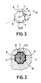
- These elongated coding pins have a coding section 5 with an N-cross section, in this case an octagonal coding section, which is held in a corresponding recess 6, the edge of which is adapted to the outline of the coding section 5, so that the coding pin is not concerned with it can turn its own axis.
- the side edges 7 of the cross-sectional shape running between two corners 8 are curved towards the axis 10 of the coding pin in relation to an imaginary straight line 9 connecting the same corners 8.
- the side edges 7 consist of circular arc sections which each extend from corner 8 to corner 8, so that the surface of the coding section 5 has concave-shaped recesses.
- the radii of the circular arc sections forming the side edges 7 are selected such that a tangent 11 applied to a side edge 7 in the area of the corners 8 encloses an angle * with the associated imaginary line 9, which is calculated as a function of the number of corners 8:
- the angle ⁇ is 22.5 o .
- the tangent 11 is then perpendicular to a line 12 which extends through the adjacent corner 8 and the diametrically opposite corner.
- the mold halves then have no undercuts, so that the coding pin can be easily removed from the mold. Due to its octagonal shape, the coding pin 3 or 4 can be inserted into the recess 6 of the housing 2 in eight different positions, so that a total of eight different voltages can be coded.
- the connector set comprises two types of coding pins 3 and 4, which are of different lengths. So z. B. in Fig. 1, the right connector half 1 with a long coding pin, while the left connector half 1 'is provided with a shorter coding pin. Both coding pins in their free end pointing towards the mating face have a flattened area in which the two ends of the coding pins overlap. This enables the two connector halves 1 and 1 'to be plugged together by pushing the two coding pins 3 and 4 over one another.
- FIG. 4 shows two connector halves 1 and 1 ′′, a long coding pin 3 being inserted in both connector halves. It can be seen that the connector halves 1 and 1 '' cannot therefore be plugged together.
- the length of the coding pins is dimensioned such that the contacts, not shown here for the sake of clarity, do not touch in the position shown in FIG. 4.
- the coding pins can be read into the housing 2 of the individual in eight different positions Insert connector halves 1, 1 ', 1''.
- the connector halves can only be plugged in if the coding pins are inserted in the same position on two connector halves. If the coding pins are not installed in the same position, they already meet with the end faces of their free ends so that the connector halves cannot be plugged together. Due to the special cross-sectional shape of the coding sections 5 and the correspondingly adapted recess in the housings 2, the play of the coding pins 3 and 4 in the recesses with respect to a rotation about their own axis 10 is also very small if no tight manufacturing tolerances are observed.
Landscapes
- Details Of Connecting Devices For Male And Female Coupling (AREA)
Applications Claiming Priority (2)
| Application Number | Priority Date | Filing Date | Title |
|---|---|---|---|
| DE9004382U DE9004382U1 (de) | 1990-04-17 | 1990-04-17 | Steckverbindersatz |
| DE9004382U | 1990-04-17 |
Publications (2)
| Publication Number | Publication Date |
|---|---|
| EP0459026A1 true EP0459026A1 (fr) | 1991-12-04 |
| EP0459026B1 EP0459026B1 (fr) | 1995-03-08 |
Family
ID=6852973
Family Applications (1)
| Application Number | Title | Priority Date | Filing Date |
|---|---|---|---|
| EP90124143A Expired - Lifetime EP0459026B1 (fr) | 1990-04-17 | 1990-12-13 | Ensemble fiche et prise |
Country Status (3)
| Country | Link |
|---|---|
| EP (1) | EP0459026B1 (fr) |
| BG (1) | BG60060B2 (fr) |
| DE (2) | DE9004382U1 (fr) |
Cited By (2)
| Publication number | Priority date | Publication date | Assignee | Title |
|---|---|---|---|---|
| DE4133120A1 (de) * | 1991-10-05 | 1993-04-08 | Tesch Ag | Brille mit gelenkig mit der fassung der glaeser verbundenen haltebuegeln |
| US6796812B2 (en) * | 2001-03-12 | 2004-09-28 | Fischer Connectors Holding S.A. | Multipole electrical connector |
Families Citing this family (2)
| Publication number | Priority date | Publication date | Assignee | Title |
|---|---|---|---|---|
| US5096443A (en) * | 1990-11-29 | 1992-03-17 | Siemens Aktiengesellschaft | Keyed apparatus for providing ground, power or signal connections |
| DE29505357U1 (de) * | 1995-03-30 | 1995-05-18 | Numatics GmbH, 53757 Sankt Augustin | Schutz- und Führungskorpus für Steckkontakte |
Citations (3)
| Publication number | Priority date | Publication date | Assignee | Title |
|---|---|---|---|---|
| DE526771C (de) * | 1931-06-10 | Voigt & Haeffner Akt Ges | Steckvorrichtung mit federnden Kontakthuelsen und unverwechselbaren Kontaktteilen | |
| DE558166C (de) * | 1929-11-30 | 1932-09-02 | Aeg | System von unverwechselbaren Steckvorrichtungen |
| DE8813930U1 (de) * | 1988-11-08 | 1989-01-26 | Rema Lipprandt GmbH & Co KG, 5300 Bonn | Mehrpolige Steckvorrichtung mit Universal-Steckcodierung für den Anschluß von Batterien an Elektro-Flurförderzeugen |
-
1990
- 1990-04-17 DE DE9004382U patent/DE9004382U1/de not_active Expired - Lifetime
- 1990-12-13 DE DE59008667T patent/DE59008667D1/de not_active Expired - Lifetime
- 1990-12-13 EP EP90124143A patent/EP0459026B1/fr not_active Expired - Lifetime
-
1991
- 1991-04-15 BG BG094259A patent/BG60060B2/bg unknown
Patent Citations (3)
| Publication number | Priority date | Publication date | Assignee | Title |
|---|---|---|---|---|
| DE526771C (de) * | 1931-06-10 | Voigt & Haeffner Akt Ges | Steckvorrichtung mit federnden Kontakthuelsen und unverwechselbaren Kontaktteilen | |
| DE558166C (de) * | 1929-11-30 | 1932-09-02 | Aeg | System von unverwechselbaren Steckvorrichtungen |
| DE8813930U1 (de) * | 1988-11-08 | 1989-01-26 | Rema Lipprandt GmbH & Co KG, 5300 Bonn | Mehrpolige Steckvorrichtung mit Universal-Steckcodierung für den Anschluß von Batterien an Elektro-Flurförderzeugen |
Cited By (2)
| Publication number | Priority date | Publication date | Assignee | Title |
|---|---|---|---|---|
| DE4133120A1 (de) * | 1991-10-05 | 1993-04-08 | Tesch Ag | Brille mit gelenkig mit der fassung der glaeser verbundenen haltebuegeln |
| US6796812B2 (en) * | 2001-03-12 | 2004-09-28 | Fischer Connectors Holding S.A. | Multipole electrical connector |
Also Published As
| Publication number | Publication date |
|---|---|
| DE9004382U1 (de) | 1991-08-14 |
| BG60060B2 (bg) | 1993-08-30 |
| EP0459026B1 (fr) | 1995-03-08 |
| DE59008667D1 (de) | 1995-04-13 |
Similar Documents
| Publication | Publication Date | Title |
|---|---|---|
| DE3808183C2 (fr) | ||
| DE69203171T2 (de) | Verbinder. | |
| DE4034277C2 (fr) | ||
| DE8520470U1 (de) | Elektrische Steckverbindung | |
| EP0235339B1 (fr) | Connecteur électrique multipolaire | |
| EP0459026B1 (fr) | Ensemble fiche et prise | |
| EP0354582B1 (fr) | Dispositif de connexion multiple enfichable, notamment dispositif de connexion multiple pour appareil consistant en une fiche et/ou un socle pour chariots électriques, batteries et machines de chargement, ainsi qu'un élément de connexion enfichable avec codage de tension et aussi au moins un codage ultérieur, en particulier pour batteries sèches et/ou à élément humide | |
| DE2458991A1 (de) | Buerstenanordnung fuer einen miniaturmotor | |
| EP0573396B1 (fr) | Système de connecteur | |
| DE3522797A1 (de) | Elektrische vielfachsteckvorrichtung | |
| EP0627130B2 (fr) | Connecteur enfichable | |
| DE8235771U1 (de) | Elektrischer Aktivstiftkontakt | |
| DE1615655B2 (de) | Steckergehaeuse | |
| DE2739072A1 (de) | Als einsteckteil oder aufnahmeteil verwendbare gehaeuseanordnung | |
| DE2251731B2 (de) | Verbindungsteil fuer stromschienen | |
| DE2637513A1 (de) | Steckeranordnung | |
| DE2248268A1 (de) | Zweipolige codierbare elktrische steckverbindung | |
| DE1212184B (de) | Mehradriges Kabel mit angeformtem Kupplungskoerper | |
| EP0527332B1 (fr) | Prise feuille avec moyens de guidage à ressort en un seule piece | |
| DE19652855C1 (de) | Elektrischer Steckverbinder | |
| DE2801090A1 (de) | Kupplung fuer elektrische leitungen | |
| DE2256328A1 (de) | Vielfachkontakt-verbindungsstueck | |
| DE3150651C1 (de) | Elektrische Mehrfach-Steckdose | |
| DE1202856C2 (de) | Kragensteckvorrichtung | |
| DE3625927C2 (de) | Rahmen zur Aufnahme und Halterung von Schaltelementen |
Legal Events
| Date | Code | Title | Description |
|---|---|---|---|
| PUAI | Public reference made under article 153(3) epc to a published international application that has entered the european phase |
Free format text: ORIGINAL CODE: 0009012 |
|
| 17P | Request for examination filed |
Effective date: 19910827 |
|
| AK | Designated contracting states |
Kind code of ref document: A1 Designated state(s): DE FR GB IT SE |
|
| RAP1 | Party data changed (applicant data changed or rights of an application transferred) |
Owner name: SCHALTBAU AKTIENGESELLSCHAFT |
|
| 17Q | First examination report despatched |
Effective date: 19940429 |
|
| GRAA | (expected) grant |
Free format text: ORIGINAL CODE: 0009210 |
|
| AK | Designated contracting states |
Kind code of ref document: B1 Designated state(s): DE FR GB IT SE |
|
| ET | Fr: translation filed | ||
| REF | Corresponds to: |
Ref document number: 59008667 Country of ref document: DE Date of ref document: 19950413 |
|
| GBT | Gb: translation of ep patent filed (gb section 77(6)(a)/1977) |
Effective date: 19950317 |
|
| ITF | It: translation for a ep patent filed | ||
| PLBE | No opposition filed within time limit |
Free format text: ORIGINAL CODE: 0009261 |
|
| STAA | Information on the status of an ep patent application or granted ep patent |
Free format text: STATUS: NO OPPOSITION FILED WITHIN TIME LIMIT |
|
| 26N | No opposition filed | ||
| PGFP | Annual fee paid to national office [announced via postgrant information from national office to epo] |
Ref country code: GB Payment date: 19961118 Year of fee payment: 7 |
|
| PGFP | Annual fee paid to national office [announced via postgrant information from national office to epo] |
Ref country code: FR Payment date: 19961216 Year of fee payment: 7 |
|
| PGFP | Annual fee paid to national office [announced via postgrant information from national office to epo] |
Ref country code: SE Payment date: 19961220 Year of fee payment: 7 |
|
| PG25 | Lapsed in a contracting state [announced via postgrant information from national office to epo] |
Ref country code: GB Free format text: LAPSE BECAUSE OF NON-PAYMENT OF DUE FEES Effective date: 19971213 |
|
| PG25 | Lapsed in a contracting state [announced via postgrant information from national office to epo] |
Ref country code: SE Free format text: LAPSE BECAUSE OF NON-PAYMENT OF DUE FEES Effective date: 19971214 |
|
| PG25 | Lapsed in a contracting state [announced via postgrant information from national office to epo] |
Ref country code: FR Free format text: THE PATENT HAS BEEN ANNULLED BY A DECISION OF A NATIONAL AUTHORITY Effective date: 19971231 |
|
| GBPC | Gb: european patent ceased through non-payment of renewal fee |
Effective date: 19971213 |
|
| EUG | Se: european patent has lapsed |
Ref document number: 90124143.0 |
|
| REG | Reference to a national code |
Ref country code: FR Ref legal event code: ST |
|
| PG25 | Lapsed in a contracting state [announced via postgrant information from national office to epo] |
Ref country code: IT Free format text: LAPSE BECAUSE OF NON-PAYMENT OF DUE FEES;WARNING: LAPSES OF ITALIAN PATENTS WITH EFFECTIVE DATE BEFORE 2007 MAY HAVE OCCURRED AT ANY TIME BEFORE 2007. THE CORRECT EFFECTIVE DATE MAY BE DIFFERENT FROM THE ONE RECORDED. Effective date: 20051213 |
|
| PGFP | Annual fee paid to national office [announced via postgrant information from national office to epo] |
Ref country code: DE Payment date: 20100129 Year of fee payment: 20 |
|
| PG25 | Lapsed in a contracting state [announced via postgrant information from national office to epo] |
Ref country code: DE Free format text: LAPSE BECAUSE OF EXPIRATION OF PROTECTION Effective date: 20101213 |