EP0459068A1 - Thin disc force sensor - Google Patents
Thin disc force sensor Download PDFInfo
- Publication number
- EP0459068A1 EP0459068A1 EP90810493A EP90810493A EP0459068A1 EP 0459068 A1 EP0459068 A1 EP 0459068A1 EP 90810493 A EP90810493 A EP 90810493A EP 90810493 A EP90810493 A EP 90810493A EP 0459068 A1 EP0459068 A1 EP 0459068A1
- Authority
- EP
- European Patent Office
- Prior art keywords
- thin
- measuring elements
- force sensor
- force
- sensor according
- Prior art date
- Legal status (The legal status is an assumption and is not a legal conclusion. Google has not performed a legal analysis and makes no representation as to the accuracy of the status listed.)
- Granted
Links
- 238000009434 installation Methods 0.000 claims abstract description 10
- 238000005259 measurement Methods 0.000 claims abstract description 10
- 230000000694 effects Effects 0.000 claims abstract description 6
- 239000002184 metal Substances 0.000 claims description 11
- VYPSYNLAJGMNEJ-UHFFFAOYSA-N silicon dioxide Inorganic materials O=[Si]=O VYPSYNLAJGMNEJ-UHFFFAOYSA-N 0.000 claims description 7
- 238000007740 vapor deposition Methods 0.000 claims description 7
- 239000013078 crystal Substances 0.000 claims description 6
- 239000010453 quartz Substances 0.000 claims description 5
- 239000011248 coating agent Substances 0.000 abstract description 3
- 238000000576 coating method Methods 0.000 abstract description 3
- 241001484259 Lacuna Species 0.000 abstract 2
- 208000010392 Bone Fractures Diseases 0.000 abstract 1
- 206010017076 Fracture Diseases 0.000 abstract 1
- 238000003754 machining Methods 0.000 abstract 1
- 238000000034 method Methods 0.000 description 8
- 238000003466 welding Methods 0.000 description 7
- 235000012239 silicon dioxide Nutrition 0.000 description 5
- 238000005516 engineering process Methods 0.000 description 4
- UNILWMWFPHPYOR-KXEYIPSPSA-M 1-[6-[2-[3-[3-[3-[2-[2-[3-[[2-[2-[[(2r)-1-[[2-[[(2r)-1-[3-[2-[2-[3-[[2-(2-amino-2-oxoethoxy)acetyl]amino]propoxy]ethoxy]ethoxy]propylamino]-3-hydroxy-1-oxopropan-2-yl]amino]-2-oxoethyl]amino]-3-[(2r)-2,3-di(hexadecanoyloxy)propyl]sulfanyl-1-oxopropan-2-yl Chemical compound O=C1C(SCCC(=O)NCCCOCCOCCOCCCNC(=O)COCC(=O)N[C@@H](CSC[C@@H](COC(=O)CCCCCCCCCCCCCCC)OC(=O)CCCCCCCCCCCCCCC)C(=O)NCC(=O)N[C@H](CO)C(=O)NCCCOCCOCCOCCCNC(=O)COCC(N)=O)CC(=O)N1CCNC(=O)CCCCCN\1C2=CC=C(S([O-])(=O)=O)C=C2CC/1=C/C=C/C=C/C1=[N+](CC)C2=CC=C(S([O-])(=O)=O)C=C2C1 UNILWMWFPHPYOR-KXEYIPSPSA-M 0.000 description 2
- 238000006243 chemical reaction Methods 0.000 description 2
- 238000010276 construction Methods 0.000 description 2
- 239000000835 fiber Substances 0.000 description 2
- 239000000463 material Substances 0.000 description 2
- 238000012544 monitoring process Methods 0.000 description 2
- 230000003068 static effect Effects 0.000 description 2
- SZUVGFMDDVSKSI-WIFOCOSTSA-N (1s,2s,3s,5r)-1-(carboxymethyl)-3,5-bis[(4-phenoxyphenyl)methyl-propylcarbamoyl]cyclopentane-1,2-dicarboxylic acid Chemical compound O=C([C@@H]1[C@@H]([C@](CC(O)=O)([C@H](C(=O)N(CCC)CC=2C=CC(OC=3C=CC=CC=3)=CC=2)C1)C(O)=O)C(O)=O)N(CCC)CC(C=C1)=CC=C1OC1=CC=CC=C1 SZUVGFMDDVSKSI-WIFOCOSTSA-N 0.000 description 1
- 230000006978 adaptation Effects 0.000 description 1
- 239000000853 adhesive Substances 0.000 description 1
- 230000001070 adhesive effect Effects 0.000 description 1
- 230000005540 biological transmission Effects 0.000 description 1
- 229910052681 coesite Inorganic materials 0.000 description 1
- 229940126543 compound 14 Drugs 0.000 description 1
- 229910052906 cristobalite Inorganic materials 0.000 description 1
- 230000008021 deposition Effects 0.000 description 1
- 238000013461 design Methods 0.000 description 1
- 238000001514 detection method Methods 0.000 description 1
- 230000008020 evaporation Effects 0.000 description 1
- 238000001704 evaporation Methods 0.000 description 1
- 239000010408 film Substances 0.000 description 1
- 230000004927 fusion Effects 0.000 description 1
- 230000036316 preload Effects 0.000 description 1
- 238000012545 processing Methods 0.000 description 1
- 239000000377 silicon dioxide Substances 0.000 description 1
- 239000007787 solid Substances 0.000 description 1
- 229910052682 stishovite Inorganic materials 0.000 description 1
- 239000010409 thin film Substances 0.000 description 1
- 229910052905 tridymite Inorganic materials 0.000 description 1
Images


Classifications
-
- G—PHYSICS
- G01—MEASURING; TESTING
- G01L—MEASURING FORCE, STRESS, TORQUE, WORK, MECHANICAL POWER, MECHANICAL EFFICIENCY, OR FLUID PRESSURE
- G01L5/00—Apparatus for, or methods of, measuring force, work, mechanical power, or torque, specially adapted for specific purposes
- G01L5/16—Apparatus for, or methods of, measuring force, work, mechanical power, or torque, specially adapted for specific purposes for measuring several components of force
- G01L5/167—Apparatus for, or methods of, measuring force, work, mechanical power, or torque, specially adapted for specific purposes for measuring several components of force using piezoelectric means
-
- G—PHYSICS
- G01—MEASURING; TESTING
- G01L—MEASURING FORCE, STRESS, TORQUE, WORK, MECHANICAL POWER, MECHANICAL EFFICIENCY, OR FLUID PRESSURE
- G01L5/00—Apparatus for, or methods of, measuring force, work, mechanical power, or torque, specially adapted for specific purposes
- G01L5/24—Apparatus for, or methods of, measuring force, work, mechanical power, or torque, specially adapted for specific purposes for determining value of torque or twisting moment for tightening a nut or other member which is similarly stressed
- G01L5/243—Apparatus for, or methods of, measuring force, work, mechanical power, or torque, specially adapted for specific purposes for determining value of torque or twisting moment for tightening a nut or other member which is similarly stressed using washers
-
- Y—GENERAL TAGGING OF NEW TECHNOLOGICAL DEVELOPMENTS; GENERAL TAGGING OF CROSS-SECTIONAL TECHNOLOGIES SPANNING OVER SEVERAL SECTIONS OF THE IPC; TECHNICAL SUBJECTS COVERED BY FORMER USPC CROSS-REFERENCE ART COLLECTIONS [XRACs] AND DIGESTS
- Y10—TECHNICAL SUBJECTS COVERED BY FORMER USPC
- Y10S—TECHNICAL SUBJECTS COVERED BY FORMER USPC CROSS-REFERENCE ART COLLECTIONS [XRACs] AND DIGESTS
- Y10S73/00—Measuring and testing
- Y10S73/04—Piezoelectric
Definitions
- Quartz crystal washers for measuring dynamic single and multi-component force processes have been known for about 20 years. Characteristic of these constructions is the construction in such a way that the crystals are arranged between 2 rigid solid disks and the introduced forces are largely conducted over the piezo disks. This creates a height that is about twice or three times the value of a standard washer. Examples are shown in DP 1 929 478 and CH 476 990. In industrial applications, in particular for monitoring processes, it is sufficient, thanks to modern amplifier technology, to detect only a partial magnitude of the effective forces, which is most easily achieved by connecting forces in parallel.
- the aim of the present invention is to build measuring disks whose measuring elements have at most half, ie less than 5 air gaps.
- the disks are individually welded into the measuring elements under high pretension.
- the disc surfaces are then ground with the measuring element cover discs and possibly lapped in order to obtain a perfect base.
- the measuring element cover disks can then be covered with a precisely determined vapor deposition layer using a template.
- the thin-disk force sensor according to the invention can thus be installed much more easily, more precisely and more reliably without additional adapter plates and pressure disks to be adjusted.
- its overall height can be kept considerably lower, it can correspond to that of standard washers, because no commercially available force sensors are installed, but only components thereof.
- measuring elements are used in the sensor, which can be sensitive to all 3 spatial coordinates XYZ and to moments M.
- the defined force parallel connection is achieved by means of vapor deposition from the ground initial state.
- Preloading using standardized disc elements results in a new category of thin-disc force sensors.
- the invention primarily comprises piezoelectric measuring principles combined with impedance converter or charge amplifier technology. Quartz, SiO2, is usually used as the piezo material, with which measurement cycles of up to 15 minutes are measured together with modern charge amplifiers, so that perfect static calibration is possible. Impedance converters can only detect short processes, but they can be easily integrated into the sensors. Commercially available impedance converters for pressure and force sensors are described in the specialist literature under the trademark "Piezotron transducers".
- quartz plates can be subjected to both pressure and thrust, depending on the crystal cut, quartz has proven to be the ideal material for multi-component force measurement.
- the invention can also be based on other known sensor technologies. It is conceivable that thin and thick film methods as well as capacitive methods are used, but only for one-component force measurement. However, due to the high rigidity that can be achieved, the piezoelectric principle is far more advantageous.
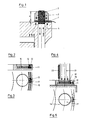
- FIG. 1 shows an application example of the thin-disk force sensor 1 according to the invention installed between the nut 2 and the cylinder cover 4 of a marine diesel engine.
- the purpose is to monitor the forces transmitted by the cylinder screw 3, which correspond to the pressure curve in the cylinder.
- FIG. 6 shows the thin-disk force sensor 1 suitable for such purposes in the plan view.
- four measuring cells 6 are installed in the metal ring disk 14 for the measurement of Z forces.
- the diameter 'd' of the built-in measuring elements 6, 7 (FIG. 10) is adapted to the application.
- Small pressure gauges 'd' have the advantage of being able to work reliably for years even in roughly machined installation conditions without breaking the piezo disks.
- All four signal electrodes point radially outwards where they are connected to the connecting cable 10 by the ring connecting line 11 in the cable duct 12.
- a preamplifier 9 is accommodated in the connection housing 8 for the purpose of impedance conversion.
- the measurement charge can also be fed directly to a charge amplifier via cable 10.
- Fig. 2 shows a section through a built-in measuring element, in which the cable duct 12 is screwed in frontally.
- the insulated ring connecting line 11 is inserted.
- FIG. 3 shows the floor plan of FIG. 2.
- the connection of the signal electrode 15 on the stripped part of the ring connecting line 11 is shown.
- the entire cable duct 12 can simply be poured out from above.
- FIG. 4 shows the welding process of a measuring element into the metal ring disk 14.
- the measuring element 6 with the stamp 21 is placed under high pressure and is welded to the metal ring disk 14 by means of laser welding via the laser welding fiber 22.
- the signal electrodes 15 are connected to the ring line 11 and all open channels are cast with a highly insulating pouring compound 13.
- the metal ring disk 14 is ground on one or both sides, depending on a pocket opening as in FIG. 4 or a through opening as in FIG Fig. 7 was chosen.
- Another suitable welding technique can also be provided.
- FIGS. 8, 9 and 10 show embodiments according to the invention of various multi-component force sensors. Such sensors are installed in processing machines, robots, in vehicle technology etc. mainly for monitoring purposes. These embodiments are shown with preamplifiers 9 for the purpose of impedance conversion. In many cases, however, it is more advantageous to supply the measurement signals directly to corresponding charge amplifiers via the connecting cable 10. Instead of the connections shown leading radially outwards, they can also be led out centrally.
- 11 and 12 show details of the embodiment in which the cable duct 12 is arranged in the central diameter circle of the metal ring disk 14.
- the electrodes then have two connection tabs 15a.
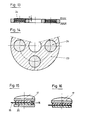
- FIG. 13 shows the application of a vapor deposition coating 24 of a predetermined height H, which can be accomplished in a simple manner according to FIG. 14 by placing a vapor deposition template 23 on it. With this layer 24 projecting from the pane surface, the proportion of the force flow flowing through the measuring element 6, 7 can be increased.
- FIG. 15 and 16 show the two disk-shaped measuring element types, FIG. 15 with metal cover plate 17, crystal plates 16, signal electrode 15 arranged in between and lower cover plate 20.
- Measuring cells with piezoceramics can be constructed in the same way.
- Both types of measuring elements are one according to known methods Unit fuses so that there is only a slight split spring effect. Instead of a fusion, an adhesive can also be provided, which also enables simple assembly.
- the invention shows that with only two types of measuring elements 6, 7 for pressure and thrust, a multitude of combinations for the multi-component force measurement can be built.
Landscapes
- Physics & Mathematics (AREA)
- General Physics & Mathematics (AREA)
- Force Measurement Appropriate To Specific Purposes (AREA)
- Measurement Of Force In General (AREA)
Abstract
Description
Es sind scheibenförmige und ringförmige Kraftsensoren auf dem Markt, die auf piezoelektrischer und Dehnmessstreifenbasis aufgebaut sind. Seit ca. 20 jahren sind vor allem Quarzkristall-Messunterlagscheiben zur Messung von dynamischen Ein- und Mehrkomponenten Kraftvorgängen bekannt geworden. Kennzeichen dieser Konstruktionen ist die Bauweise derart, dass die Kristalle zwischen 2 starren Vollscheiben angeordnet sind und die eingeleiteten Kräfte zum grössten Teil über die Piezoscheiben geleitet werden. Dadurch entsteht eine Bauhöhe, die etwa dem doppelten oder dreifachen Wert einer Standard-Unterlagscheibe entspricht. Beispiele sind in DP 1 929 478 und CH 476 990 gezeigt. In industriellen Anwendungen, insbesondere für Ueberwachungsvorgänge genügt es dank moderner Verstärkertechnik, nur eine Teilgrösse der effektiven Kräfte zu erfassen, was am einfachsten durch Kraftparallelschaltung erreicht wird. Bedingung dabei ist jedoch, dass sich in der Beobachtungszeit das Verhältnis
nicht verändert. Werte von α können im Bereich von 2 bis 10'000 varieren je nach Anwendung. Ein Kraftsensor dieser Art in Rechteckplattenform ist unter DE 34 40 670 C2 bekannt geworden. In solchen Messplatten sind handelsübliche Piezokraftmessscheiben eingeklebt, deren sehr empfindliche Einbauhöhen gegenüber der Messplattenoberfläche mittels Adapterplatten und Druckscheiben auf wenige µm genau abgeglichen werden müssen. Konsequenz dieser Hintereinanderschaltung einer Reihe von Scheiben wovon 5 schon in der handelsüblichen Kraftmessscheibe vorhanden sind, ist eine grosse Unsicherheit der Erfassung der parallel geschalteten Kraftübertragung, weil 8 hintereinandergeschaltete Scheiben zusammen mit den Auflageflächen 10 Spaltfederschichten ergeben, die je nach Vorspannung verschiedene Elastizitätsverhältnisse aufweisen. Die einzelnen Kraftmessscheiben einer solchen Messplatte werden infolge der 10 verschiedenen Luftspalte bei gleicher Belastung immer verschiedene Kraftmesssignale abgeben, da die Wirkungen der Spaltfederschichten schwer unter Kontrolle zu bringen sind.There are disc-shaped and ring-shaped force sensors on the market which are based on piezoelectric and strain gauge bases. Quartz crystal washers for measuring dynamic single and multi-component force processes have been known for about 20 years. Characteristic of these constructions is the construction in such a way that the crystals are arranged between 2 rigid solid disks and the introduced forces are largely conducted over the piezo disks. This creates a height that is about twice or three times the value of a standard washer. Examples are shown in
not changed. Values of α can vary in the range from 2 to 10,000 depending on the application. A force sensor of this type in the form of a rectangular plate is known from DE 34 40 670 C2. Commercially available piezo force measuring disks are glued into such measuring plates, their very sensitive installation heights compared to the measuring plate surface by means of adapter plates and thrust washers must be adjusted to within a few µm. The consequence of this series connection of a series of discs, 5 of which are already available in the commercially available force measuring disc, is a great uncertainty in the detection of the parallel transmission of force, because 8 discs connected in series together with the contact surfaces result in 10 split spring layers, which have different elasticity ratios depending on the preload. The individual force measuring discs of such a measuring plate will always give different force measuring signals due to the 10 different air gaps under the same load, since the effects of the split spring layers are difficult to control.
Ziel der vorliegenden Erfindung ist es, Messscheiben zu bauen, deren Messelemente höchstens die Hälfte, also weniger als 5 Luftspalte aufweisen. Zudem werden die Scheiben einzeln unter hoher Vorspannung in die Messelemente eingeschweisst. Hierauf werden die Scheibenoberflächen mit den Messelementdeckscheiben überschliffen und ev. geläppt, um eine einwandfreie Ausgangsbasis zu erhalten. Anschliessend können die Messelementdeckscheiben mittels Schablone mit einer genau bestimmten Aufdampfschicht belegt werden. Damit ist der erfindungsgemässe Dünnscheiben-Kraftsensor ohne zusätzlich abzustimmende Adapterplatten und Druckscheiben wesentlich einfacher, genauer und zuverlässiger einbaubar. Zudem kann seine Bauhöhe erheblich geringer gehalten werden, sie kann derjenigen von Standard-Unterlagscheiben entsprechen, weil keine handelsüblichen Kraftsensoren eingebaut werden, sondern nur Komponenten davon.The aim of the present invention is to build measuring disks whose measuring elements have at most half, ie less than 5 air gaps. In addition, the disks are individually welded into the measuring elements under high pretension. The disc surfaces are then ground with the measuring element cover discs and possibly lapped in order to obtain a perfect base. The measuring element cover disks can then be covered with a precisely determined vapor deposition layer using a template. The thin-disk force sensor according to the invention can thus be installed much more easily, more precisely and more reliably without additional adapter plates and pressure disks to be adjusted. In addition, its overall height can be kept considerably lower, it can correspond to that of standard washers, because no commercially available force sensors are installed, but only components thereof.
Erfindungsgemäss werden Messelemente in den Sensor eingesetzt, die in allen 3 Raumkoordinationen XYZ sowie auf Momente M empfindlich sein können. Die definierte Kraftparallelschaltung wird erreicht mittels Aufdampftechnik aus dem überschliffenen Ausgangszustand. Die Reduktion der Anzahl der Spaltfederschichten und deren Minimierung durch Einschweissung unter hoher mechan. Vorspannung unter Verwendung standardisierter Scheibenelemente ergibt eine neue Kategorie von Dünnscheiben Kraftsensoren.According to the invention, measuring elements are used in the sensor, which can be sensitive to all 3 spatial coordinates XYZ and to moments M. The defined force parallel connection is achieved by means of vapor deposition from the ground initial state. The reduction in the number of split spring layers and minimizing them by welding under high mechanical. Preloading using standardized disc elements results in a new category of thin-disc force sensors.
Die Erfindung umfasst in erster Linie piezoelektrische Messprinzipien, verbunden mit Impedanzwandler- oder Ladungsverstärkertechnik. Als Piezomaterial wird üblicherweise Quarz, SiO2, verwendet, mit dem gemeinsam mit modernen Ladungsverstärkern Messzyklen bis 15 Minuten Dauer gemessen werden, sodass einwandfreie statische Kalibrierung möglich ist. Mit Impedanzwandlern können nur Kurzvorgänge erfasst werden, sie können jedoch auf einfache Weise mit in die Sensoren integriert werden. Handelsübliche Impedanzwandler für Druck- und Kraftsensoren sind unter der Handelsmarke "Piezotronaufnehmer" in der Fachliteratur beschrieben.The invention primarily comprises piezoelectric measuring principles combined with impedance converter or charge amplifier technology. Quartz, SiO2, is usually used as the piezo material, with which measurement cycles of up to 15 minutes are measured together with modern charge amplifiers, so that perfect static calibration is possible. Impedance converters can only detect short processes, but they can be easily integrated into the sensors. Commercially available impedance converters for pressure and force sensors are described in the specialist literature under the trademark "Piezotron transducers".
Die Verwendung von Piezokeramiken ergibt wohl grössere Signale, die aber nur für Kurzzeitmessvorgänge nutzbar sind, statische Kalibrierung ist erschwert möglich, sie ermöglichen jedoch wesentlich kleinere Elementgrössen, was Vorteile haben kann. Weil Quarzplatten je nach Kristallschnitt sowohl auf Druck wie auch auf Schub beansprucht werden können, hat sich Quarz jedoch als das ideale Material für die Mehrkomponenten-Kraftmessung erwiesen.The use of piezoceramics results in larger signals, but these can only be used for short-term measurements, static calibration is difficult, but they enable much smaller element sizes, which can have advantages. Because quartz plates can be subjected to both pressure and thrust, depending on the crystal cut, quartz has proven to be the ideal material for multi-component force measurement.
Die Erfindung kann jedoch auch auf andere bekannte Sensortechniken aufbauen. So ist es denkbar, dass Dünn- und Dickfilmverfahren, sowie kapazitive Verfahren angewendet werden, allerdings nur für Einkomponenten-Kraftmessung. Infolge der erreichbaren hohen Steifigkeit ist das piezoelektrische Prinzip jedoch weit vorteilhafter.However, the invention can also be based on other known sensor technologies. It is conceivable that thin and thick film methods as well as capacitive methods are used, but only for one-component force measurement. However, due to the high rigidity that can be achieved, the piezoelectric principle is far more advantageous.
Die folgenden Ausführungen beziehen sich deshalb ausschliesslich auf piezoelektrische Anordnungen.The following explanations therefore relate exclusively to piezoelectric arrangements.
Die Erfindung soll anhand folgender Figuren näher erläutert werden:
- Fig. 1
- zeigt eine Anwendung des Dünnscheiben-Kraftsensors
- Fig. 2
- zeigt ein eingebautes Messelement im Schnitt
- Fig. 3
- zeigt den Grundriss von Fig. 2
- Fig. 4
- zeigt den Einschweissvorgang des Messelementes in die Sensorscheibe
- Fig. 5
- zeigt den Grundriss von Fig. 4
- Fig. 6
- zeigt den Grundriss eines Dünnscheiben-Kraftsensors, wie er in Fig. 1 angewendet wird
- Fig 7
- zeigt einen Schnitt A-A von Fig. 6
- Fig. 8
- zeigt einen Dünnscheiben-Kraftsensor, der 3 Koordinatenkräfte XYZ erfasst
- Fig. 9
- zeigt einen Dünnscheiben-Kraftsensor, der Drehmoment und Achsialkraft erfasst
- Fig. 10
- zeigt einen Dünnscheiben-Kraftsensor, der die 3 Koordinaten und ein Drehmoment erfasst
- Fig. 11
- zeigt ein Detail des Signalkanals
- Fig. 12
- zeigt den Grundriss von Fig. 11
- Fig. 13
- zeigt einen Querschnitt
- Fig. 14
- zeigt die Aufdampfschablone zu Fig. 13
- Fig. 15
- zeigt ein Einbau-Messelement im Schnitt
- Fig. 16
- zeigt ein Einbau-Messelement im Schnitt
- Fig. 1
- shows an application of the thin-disc force sensor
- Fig. 2
- shows a built-in measuring element in section
- Fig. 3
- shows the floor plan of Fig. 2nd
- Fig. 4
- shows the welding process of the measuring element in the sensor disc
- Fig. 5
- shows the floor plan of FIG. 4
- Fig. 6
- shows the outline of a thin-disk force sensor, as used in Fig. 1
- Fig. 7
- shows a section AA of FIG. 6
- Fig. 8
- shows a thin-disk force sensor that detects 3 coordinate forces XYZ
- Fig. 9
- shows a thin-disc force sensor that detects torque and axial force
- Fig. 10
- shows a thin-disk force sensor that detects the 3 coordinates and a torque
- Fig. 11
- shows a detail of the signal channel
- Fig. 12
- shows the floor plan of FIG. 11
- Fig. 13
- shows a cross section
- Fig. 14
- shows the vapor deposition template for FIG. 13
- Fig. 15
- shows a built-in measuring element in section
- Fig. 16
- shows a built-in measuring element in section
Fig. 1 zeigt ein Anwendungsbeispiel des erfindungsgemässen Dünnscheiben-Kraftsensors 1 eingebaut zwischen Mutter 2 und Zylinderdeckel 4 eines Schiffsdieselmotors. Zweck ist die Ueberwachung der von der Zylinderschraube 3 übertragenen Kräfte, welche dem Druckverlauf im Zylinder entsprechen. Hier ist es wichtig, einen Kraftsensor zu haben, der den Dimensionen normaler Unterlagscheiben entspricht, so dass diese durch Auswechseln mit Dünnscheiben-Kraftsensoren ersetzt werden können ohne mechanische Veränderungen notwendig zu machen.1 shows an application example of the thin-
Fig. 6 zeigt den für solche Zwecke geeigneten Dünnscheiben-Kraftsensor 1 im Grundriss. In der Metallringscheibe 14 sind als Beispiel vier Messzellen 6 eingebaut für die Messung von Z-Kräften. Der Durchmesser 'd' der eingebauten Messelemente 6,7 (Fig. 10) wird der Anwendung angepasst. Kleine Druckmesser 'd' haben den Vorteil, auch in grobbearbeiteten Einbauzuständen ohne Bruch der Piezoscheiben, jahrelang zuverlässig arbeiten zu können. Alle vier Signalelektroden weisen radial nach aussen, wo sie durch die Ring-Anschlussleitung 11 im Kabelkanal 12 mit dem Anschlusskabel 10 verbunden sind. In vielen Fällen wird zwecks Impedanzwandlung ein Vorverstärker 9 im Anschlussgehäuse 8 untergebracht. Die Messladung kann aber auch direkt über Kabel 10 einem Ladungsverstärker zugeführt werden.6 shows the thin-
Fig. 2 zeigt einen Schnitt durch ein eingebautes Messelement, bei dem der Kabelkanal 12 frontal eingedreht ist. Eingelegt ist die isolierte Ring-Anschlussleitung 11.Fig. 2 shows a section through a built-in measuring element, in which the
Fig. 3 zeigt den Grundriss von Fig. 2. Dargestellt ist der Anschluss der Signalelektrode 15 auf dem abisolierten Teil der Ring-Anschlussleitung 11. Der ganze Kabelkanal 12 kann einfach von oben ausgegossen werden.FIG. 3 shows the floor plan of FIG. 2. The connection of the
Fig. 4 zeigt den Einschweissvorgang eines Messelementes in die Metallringscheibe 14. Dazu wird das Messelement 6 mit dem Stempel 21 unter hohen Druck gestellt und mittels Laserschweissung über die Laserschweissfaser 22 mit der Metallringscheibe 14 verschweisst. Hierauf werden die Signalelektroden 15 an die Ringleitung 11 angeschlossen und alle offenen Kanäle mit einer hochisolierenden Ausgussmasse 13 vergossen. Nach Trocknen der Ausgussmasse 13 wird die Metallringscheibe 14 einseitig oder beidseitig überschliffen, je nachdem eine Sacköffnung wie in Fig. 4 oder eine Durchgangsöffnung wie in Fig. 7 gewählt wurde. Es kann aber auch eine andere geeignete Schweisstechnik vorgesehen werden.4 shows the welding process of a measuring element into the
Fig. 8, 9 und 10 zeigen erfindungsgemässe Ausführungsformen verschiedener Mehrkomponenten-Kraftsensoren. Solche Sensoren werden in Bearbeitungsmaschinen, Robotern, in der Fahrzeugtechnik etc. hauptsächlich zu Ueberwachungszwecken eingebaut. Diese Ausführungsformen sind mit Vorverstärkern 9 zwecks Impedanzwandlung dargestellt. Es ist in vielen Fällen aber vorteilhafter, die Messsignale direkt über das Anschlusskabel 10 entsprechenden Ladungsverstärkern zuzuführen. Anstelle der dargestellten radial nach aussen führenden Anschlüsse können diese auch zentral herausgeführt werden.8, 9 and 10 show embodiments according to the invention of various multi-component force sensors. Such sensors are installed in processing machines, robots, in vehicle technology etc. mainly for monitoring purposes. These embodiments are shown with
Fig. 11 und 12 zeigen Details der Ausführungsform, bei welcher der Kabelkanal 12 im mittleren Durchmesserkreis der Metallringscheibe 14 angeordnet ist. Die Elektroden haben dann zwei Anschlusslappen 15a.11 and 12 show details of the embodiment in which the
Fig. 13 zeigt das Aufbringen eines Aufdampfbelages 24 von vorbestimmter Höhe H, was nach Fig. 14 durch Auflegen einer Aufdampfschablone 23 auf einfache Weise bewerkstelligt werden kann. Mit dieser aus der Scheibenoberfläche herausragenden Schicht 24 kann der Anteil des durch das Messelement 6, 7 fliessenden Kraftflusses erhöht werden.FIG. 13 shows the application of a
Fig. 15 und 16 zeigen die beiden scheibenförmigen Messelementtypen, Fig. 15 mit Metalldeckscheibe 17, Kristallscheiben 16, dazwischen angeordneter Signalelektrode 15 und unterer Deckscheibe 20. Messzellen mit Piezokeramiken können auf gleiche Weise aufgebaut sein.15 and 16 show the two disk-shaped measuring element types, FIG. 15 with
Fig. 16 zeigt denselben Messelementtyp, jedoch ohne untere Deckscheibe.16 shows the same type of measuring element, but without a lower cover plate.
Beide Messelementtypen sind nach bekannten Methoden zu einer Einheit fusioniert, so dass nur eine geringe Spaltfederwirkung auftritt. Anstelle einer Fusion kann auch eine Klebung vorgesehen werden, die ebenfalls eine einfache Montage ermöglicht.Both types of measuring elements are one according to known methods Unit fuses so that there is only a slight split spring effect. Instead of a fusion, an adhesive can also be provided, which also enables simple assembly.
Die Erfindung zeigt, dass mit nur zwei Messelementtypen 6, 7 für Druck und Schub eine Vielzahl von Kombinationen für die Mehrkomponenten-Kraftmessung gebaut werden kann. Der Einbau von vormontierten Messelementen 6, 7 mit möglichst dünnen Scheiben in Trägerscheiben, welche die Form von kreisförmigen Metallringen, aber auch andere Formen haben können, ergibt einfache Anpassung an komplexe Einbaufälle.The invention shows that with only two types of measuring
Durch die erfindungsgemässe Reduktion der Spaltfederwirkungen auf ein Mindestmass ergibt sich eine Zuverlässigkeit, in der Gleichheit der Ausgangssignale verschiedener Messelemente mit gleicher Funktion, wobei die Signale vorausbestimmbar sind, wie dies bisher nicht möglich war. Zudem ist der Einbau solcher Dünnschicht-Kraftsensoren wesentlich einfacher, da keine Adapterplatten und Druckscheiben ausgemessen und bei der Montage eingelegt werden müssen.By reducing the split spring effects according to the invention to a minimum, there is a reliability in the equality of the output signals of different measuring elements with the same function, the signals being predeterminable, as was previously not possible. In addition, the installation of such thin-film force sensors is much easier, since no adapter plates and pressure plates have to be measured and inserted during assembly.
Infolge der wesentlich steiferen Bauart genügen Aufdampfschichten von wenigen µm um die gewünschte Signalgrösse zu erreichen. Durch richtige Wahl der zulässigen Elementdurchmesser 'd' können Dünnscheiben-Kraftsensoren gebaut werden, die den schwierigsten Einbauverhältnissen gerecht werden und auch langzeitig keine Kristallbrüche vorweisen.Due to the much stiffer design, vapor deposition layers of a few µm are sufficient to achieve the desired signal size. By correctly selecting the permissible element diameter 'd', thin-disc force sensors can be built that can cope with the most difficult installation conditions and do not show any crystal breaks for a long time.
- 11
- Dünnscheiben-KraftsensorThin-disc force sensor
- 22nd
- Muttermother
- 33rd
- ZylinderdeckelschraubeCylinder cover screw
- 44th
- ZylinderdeckelCylinder cover
- 66
- Messelement für Druckkraft ZMeasuring element for compressive force Z
- 77
- Messelement für Schubkraft XYZShear force measuring element XYZ
- 88th
- AnschlussgehäuseJunction box
- 99
- VorverstärkerPreamplifier
- 1010th
- Anschlusskabel, AnschlussleitungConnection cable, connection line
- 1111
- Ring AnschlussleitungRing connecting cable
- 1212
- KabelkanalCabel Canal
- 1313
- AusgussmassePouring compound
- 1414
- MetallringscheibeMetal washer
- 1515
-
Signalelektrode mit Anschlusslappen 15aSignal electrode with
connection tab 15a - 1616
- MetallscheibeMetal disc
- 1717th
- MetalldeckscheibeMetal cover plate
- 2020th
- Untere DeckscheibeLower cover plate
- 2121
- PressstempelPress stamp
- 2222
- LaserschweissfaserLaser welding fiber
- 2323
- AufdampfschabloneEvaporation template
- 2424th
- AufdampfbelagEvaporative coating
- HH
- Höhe des AufdampfbelagesDeposition level
Claims (11)
Priority Applications (1)
| Application Number | Priority Date | Filing Date | Title |
|---|---|---|---|
| JP3129718A JPH04231827A (en) | 1990-05-31 | 1991-05-31 | Thin-disk-state force sensor |
Applications Claiming Priority (2)
| Application Number | Priority Date | Filing Date | Title |
|---|---|---|---|
| CH1839/90A CH680689A5 (en) | 1990-05-31 | 1990-05-31 | |
| CH1839/90 | 1990-05-31 |
Publications (2)
| Publication Number | Publication Date |
|---|---|
| EP0459068A1 true EP0459068A1 (en) | 1991-12-04 |
| EP0459068B1 EP0459068B1 (en) | 1994-11-30 |
Family
ID=4219807
Family Applications (1)
| Application Number | Title | Priority Date | Filing Date |
|---|---|---|---|
| EP90810493A Expired - Lifetime EP0459068B1 (en) | 1990-05-31 | 1990-06-29 | Thin disc force sensor |
Country Status (5)
| Country | Link |
|---|---|
| US (1) | US5297430A (en) |
| EP (1) | EP0459068B1 (en) |
| AT (1) | ATE114810T1 (en) |
| CH (1) | CH680689A5 (en) |
| DE (1) | DE59007866D1 (en) |
Cited By (5)
| Publication number | Priority date | Publication date | Assignee | Title |
|---|---|---|---|---|
| EP0594534A1 (en) * | 1992-10-23 | 1994-04-27 | K.K. Holding Ag | Multicomponent force and moment measurement |
| DE19831270A1 (en) * | 1998-07-13 | 2000-01-27 | Peter Haug | Sensor for determining and monitoring tension in fastening, especially screw; has piezoelectric plastics bonded to it, with circuitry determining potential developed under stress |
| WO2010071607A1 (en) * | 2008-12-17 | 2010-06-24 | Vestas Wind System A/S | Method and system for monitoring fastener loads |
| CN108386437A (en) * | 2018-01-11 | 2018-08-10 | 深圳市远望谷信息技术股份有限公司 | A kind of fastener |
| EP3859294A1 (en) | 2020-01-29 | 2021-08-04 | Piezocryst Advanced Sensorics GmbH | Structured piezoelectric sensor element |
Families Citing this family (30)
| Publication number | Priority date | Publication date | Assignee | Title |
|---|---|---|---|---|
| DE4336773C2 (en) * | 1993-10-28 | 1997-09-11 | Bosch Gmbh Robert | Device for measuring pressures, forces and moments |
| CH689599A5 (en) * | 1993-11-23 | 1999-06-30 | Kk Holding Ag | Transducer arrangement for installation in carriageways for the purpose of detecting the weights and / or the driving dynamic reactions of vehicle wheels. |
| CH690865A5 (en) * | 1996-05-09 | 2001-02-15 | Kk Holding Ag | Force and torque measurement arrangement. |
| NO302715B1 (en) * | 1996-06-19 | 1998-04-14 | Scan Mag Sense As | Device for measuring compressive forces |
| US5887732A (en) * | 1997-02-07 | 1999-03-30 | The Interlake Companies, Inc. | Rack with heavy duty rollers in back |
| US6247364B1 (en) | 1997-10-27 | 2001-06-19 | Thomas P. Kicher & Co. | Acceleration transducer and method |
| DE10142644A1 (en) * | 2001-08-31 | 2003-04-03 | Lucas Automotive Gmbh | Motorized disc brake |
| JP5356218B2 (en) * | 2006-05-04 | 2013-12-04 | キストラー ホールディング アクチエンゲゼルシャフト | Piezoelectric measuring element with lateral effect and sensor including said measuring element |
| DE202012100578U1 (en) | 2011-02-22 | 2012-03-22 | Mike Schubert | Force measuring device |
| JP5742415B2 (en) * | 2011-04-14 | 2015-07-01 | セイコーエプソン株式会社 | Sensor device, force detection device and robot |
| JP2013101020A (en) | 2011-11-08 | 2013-05-23 | Seiko Epson Corp | Sensor element, force detection device and robot |
| JP5811785B2 (en) | 2011-11-08 | 2015-11-11 | セイコーエプソン株式会社 | Sensor element, force detection device and robot |
| CN103108154A (en) | 2011-11-14 | 2013-05-15 | 辉达公司 | Automobile navigation equipment |
| JP5880935B2 (en) | 2011-12-20 | 2016-03-09 | セイコーエプソン株式会社 | Sensor device, sensor module, robot, and manufacturing method of sensor device |
| JP5880934B2 (en) | 2011-12-20 | 2016-03-09 | セイコーエプソン株式会社 | Sensor device, sensor module, force detection device, robot |
| JP5895615B2 (en) | 2012-03-09 | 2016-03-30 | セイコーエプソン株式会社 | Sensor module, force detection device and robot |
| DE102012005555B3 (en) * | 2012-03-21 | 2013-08-22 | Audi Ag | Measuring plate for use in bearing surface of slide damper of press for measuring tension-, pressure- or shear forces, has recesses, in which sensors are mounted under pre-tension for measuring forces by pressure piece |
| JP6051678B2 (en) | 2012-08-22 | 2016-12-27 | セイコーエプソン株式会社 | Sensor device, sensor module, force detection device and robot |
| DE102013000597A1 (en) * | 2013-01-16 | 2014-07-17 | Sms Tenzotherm Gmbh | Force plate manufacturing method, involves arranging strain sensor in region that is open in radial direction between two bars, and allowing bars to extend themselves outwardly within plane of annular plate element penetrable with screw |
| JP6163900B2 (en) | 2013-06-13 | 2017-07-19 | セイコーエプソン株式会社 | Force detection device and robot |
| US9705069B2 (en) | 2013-10-31 | 2017-07-11 | Seiko Epson Corporation | Sensor device, force detecting device, robot, electronic component conveying apparatus, electronic component inspecting apparatus, and component machining apparatus |
| US9784627B2 (en) | 2013-11-27 | 2017-10-10 | Panasonic Intellectual Property Management Co., Ltd. | Load sensor, load detector including load sensor, and method for detecting load |
| KR101839073B1 (en) | 2016-08-26 | 2018-03-16 | 고려대학교 세종산학협력단 | Detecting apparatus for loosen bolt-nut using variation of capacitance |
| EP3526565A1 (en) * | 2016-10-17 | 2019-08-21 | Kistler Holding AG | Force and torque sensor, force transducer module for such a force and torque sensor and robot having such a force and torque sensor |
| US11585366B2 (en) * | 2017-08-30 | 2023-02-21 | Bollhoff Otalu S.A. | Fixing device and method for manufacturing such a device |
| FR3070468B1 (en) * | 2017-08-30 | 2020-02-21 | Bollhoff Otalu S.A. | FIXING DEVICE AND METHOD FOR MANUFACTURING SUCH A DEVICE |
| AT520901B1 (en) | 2018-01-24 | 2019-11-15 | Avl List Gmbh | Measuring device and method for determining a force and / or a torque on a torque transmitting shaft |
| AT521702B1 (en) | 2019-03-11 | 2020-04-15 | Piezocryst Advanced Sensorics | MEASURING SYSTEM, SUITABLE FOR INSTALLATION BETWEEN TORQUE AND / OR FORCE TRANSMISSION MACHINE PARTS |
| EP3881969A1 (en) | 2020-03-19 | 2021-09-22 | Kistler Holding AG | Cutting machine with a force sensor, use of such a cutting machine and method for calibrating the force sensor of such a cutting machine |
| IT202100006203A1 (en) * | 2021-03-16 | 2022-09-16 | Brembo Spa | DEVICE AND METHOD FOR DETECTING THE BRAKING FORCE AND/OR TORQUE IN CORRESPONDENCE WITH A BRAKE CALIPER |
Citations (3)
| Publication number | Priority date | Publication date | Assignee | Title |
|---|---|---|---|---|
| CH476990A (en) * | 1968-07-30 | 1969-08-15 | Kistler Instrumente Ag | Force transducer with at least one piezo element arranged between two force transmission bearings |
| CH502590A (en) * | 1968-11-04 | 1971-01-31 | Kistler Instrumente Ag | Force and / or torque measurement arrangement |
| DE3440670C2 (en) * | 1984-11-07 | 1986-10-23 | Prometec GmbH, 5100 Aachen | Device for measuring the forces and moments acting on machine components |
Family Cites Families (5)
| Publication number | Priority date | Publication date | Assignee | Title |
|---|---|---|---|---|
| US3210993A (en) * | 1961-10-27 | 1965-10-12 | Endevco Corp | Electromechanical transducer utilizing poisson ratio effects |
| US4092856A (en) * | 1977-05-13 | 1978-06-06 | The United States Of America As Represented By The Secretary Of The Army | Kilobar range stress gauge |
| US4425808A (en) * | 1982-02-26 | 1984-01-17 | The United States Of America As Represented By The Administrator Of The National Aeronautics And Space Administration | Thin film strain transducer |
| DE3680341D1 (en) * | 1986-11-07 | 1991-08-22 | Kristal Instr Ag | MULTI-COMPONENT DYNAMOMETER. |
| US5151258A (en) * | 1991-05-30 | 1992-09-29 | General Electric Company | NOx reduction and control using hydrogen peroxide in the absorber column |
-
1990
- 1990-05-31 CH CH1839/90A patent/CH680689A5/de not_active IP Right Cessation
- 1990-06-29 DE DE59007866T patent/DE59007866D1/en not_active Expired - Fee Related
- 1990-06-29 AT AT90810493T patent/ATE114810T1/en not_active IP Right Cessation
- 1990-06-29 EP EP90810493A patent/EP0459068B1/en not_active Expired - Lifetime
-
1991
- 1991-05-31 US US07/708,372 patent/US5297430A/en not_active Expired - Lifetime
Patent Citations (3)
| Publication number | Priority date | Publication date | Assignee | Title |
|---|---|---|---|---|
| CH476990A (en) * | 1968-07-30 | 1969-08-15 | Kistler Instrumente Ag | Force transducer with at least one piezo element arranged between two force transmission bearings |
| CH502590A (en) * | 1968-11-04 | 1971-01-31 | Kistler Instrumente Ag | Force and / or torque measurement arrangement |
| DE3440670C2 (en) * | 1984-11-07 | 1986-10-23 | Prometec GmbH, 5100 Aachen | Device for measuring the forces and moments acting on machine components |
Non-Patent Citations (1)
| Title |
|---|
| PIEZOELEKTRISCHE MESSTECHNIK, 1980, Springer-Verlag, Berlin, Heidelberg, New York J. TICHY, G. GAUTSCHI Seiten 162-165 * Seite 162, Bild 9.1 * * |
Cited By (8)
| Publication number | Priority date | Publication date | Assignee | Title |
|---|---|---|---|---|
| EP0594534A1 (en) * | 1992-10-23 | 1994-04-27 | K.K. Holding Ag | Multicomponent force and moment measurement |
| DE19831270A1 (en) * | 1998-07-13 | 2000-01-27 | Peter Haug | Sensor for determining and monitoring tension in fastening, especially screw; has piezoelectric plastics bonded to it, with circuitry determining potential developed under stress |
| DE19831270B4 (en) * | 1998-07-13 | 2005-09-29 | Peter Haug | Arrangement and method for determining and monitoring the state of stress of a fastening element |
| WO2010071607A1 (en) * | 2008-12-17 | 2010-06-24 | Vestas Wind System A/S | Method and system for monitoring fastener loads |
| CN108386437A (en) * | 2018-01-11 | 2018-08-10 | 深圳市远望谷信息技术股份有限公司 | A kind of fastener |
| EP3859294A1 (en) | 2020-01-29 | 2021-08-04 | Piezocryst Advanced Sensorics GmbH | Structured piezoelectric sensor element |
| AT523511A1 (en) * | 2020-01-29 | 2021-08-15 | Piezocryst Advanced Sensorics | Structured, piezoelectric sensor element |
| AT523511B1 (en) * | 2020-01-29 | 2021-10-15 | Piezocryst Advanced Sensorics | Structured, piezoelectric sensor element |
Also Published As
| Publication number | Publication date |
|---|---|
| US5297430A (en) | 1994-03-29 |
| EP0459068B1 (en) | 1994-11-30 |
| CH680689A5 (en) | 1992-10-15 |
| DE59007866D1 (en) | 1995-01-12 |
| ATE114810T1 (en) | 1994-12-15 |
Similar Documents
| Publication | Publication Date | Title |
|---|---|---|
| EP0459068B1 (en) | Thin disc force sensor | |
| EP3507580B1 (en) | Torque sensor with a radially elastic torque transfer | |
| EP3507582B1 (en) | Torque sensor with seal membrane | |
| EP0270693B1 (en) | Multiple component dynamometer | |
| EP3507581B1 (en) | Torque sensor having a shunt spoke | |
| DE69133193T2 (en) | Method for producing a capacitive detector with three substrates, surrounding regions and a working body (force, acceleration, magnetic) | |
| DE102006019942B4 (en) | Force measuring device for measuring the force in solid state actuators, methods for measuring a force and use of the force measuring device | |
| EP0459948A2 (en) | Receiver-combination for force, elongation and sound conducted through solids | |
| DE3811311C1 (en) | ||
| EP0016858B1 (en) | Piezoelectric transducer for mounting in pressure, force or acceleration sensing devices | |
| AT402116B (en) | SPARK PLUG WITH A FORCE MEASUREMENT ELEMENT FOR MEASURING THE PRESSURE AT THE SPARK PLUG | |
| EP0902267B1 (en) | Pressure transducer with compensation for acceleration effects | |
| EP0459069B1 (en) | Intermediate layer force sensor with parallel connected disc sensor elements and integrated amplifiers | |
| EP3491355B1 (en) | Force measuring device for multi-axis measurement of active forces and moments | |
| DE1929478A1 (en) | Piezo measuring cell | |
| DE6940548U (en) | MULTI-COMPONENT FORCE AND TORQUE MEASUREMENT ARRANGEMENT | |
| EP1590641A1 (en) | Measuring sensor comprising a pre-stressing device | |
| EP3304018B1 (en) | Force components receiver and multiple force components receiver as well as the use of such multiple force component receiver | |
| DE19601078C2 (en) | Pressure force sensor | |
| DE3423711A1 (en) | Pickup for measuring hot media, and method for installing it | |
| DE3912218A1 (en) | LOAD MEASURING DEVICE | |
| DE102004033925B4 (en) | Torque transducer | |
| EP0179278A2 (en) | Pressure sensor | |
| DE19545091B4 (en) | Measuring instrument with a pressure transducer | |
| EP2585802A1 (en) | Piezoresistive force sensor |
Legal Events
| Date | Code | Title | Description |
|---|---|---|---|
| PUAI | Public reference made under article 153(3) epc to a published international application that has entered the european phase |
Free format text: ORIGINAL CODE: 0009012 |
|
| AK | Designated contracting states |
Kind code of ref document: A1 Designated state(s): AT DE FR GB |
|
| 17P | Request for examination filed |
Effective date: 19920511 |
|
| RAP1 | Party data changed (applicant data changed or rights of an application transferred) |
Owner name: K.K. HOLDING AG |
|
| 17Q | First examination report despatched |
Effective date: 19930413 |
|
| GRAA | (expected) grant |
Free format text: ORIGINAL CODE: 0009210 |
|
| AK | Designated contracting states |
Kind code of ref document: B1 Designated state(s): AT DE FR GB |
|
| REF | Corresponds to: |
Ref document number: 114810 Country of ref document: AT Date of ref document: 19941215 Kind code of ref document: T |
|
| GBT | Gb: translation of ep patent filed (gb section 77(6)(a)/1977) |
Effective date: 19941212 |
|
| REF | Corresponds to: |
Ref document number: 59007866 Country of ref document: DE Date of ref document: 19950112 |
|
| ET | Fr: translation filed | ||
| PLBE | No opposition filed within time limit |
Free format text: ORIGINAL CODE: 0009261 |
|
| STAA | Information on the status of an ep patent application or granted ep patent |
Free format text: STATUS: NO OPPOSITION FILED WITHIN TIME LIMIT |
|
| 26N | No opposition filed | ||
| PGFP | Annual fee paid to national office [announced via postgrant information from national office to epo] |
Ref country code: FR Payment date: 19970418 Year of fee payment: 8 |
|
| PGFP | Annual fee paid to national office [announced via postgrant information from national office to epo] |
Ref country code: GB Payment date: 19980622 Year of fee payment: 9 |
|
| PGFP | Annual fee paid to national office [announced via postgrant information from national office to epo] |
Ref country code: AT Payment date: 19980629 Year of fee payment: 9 |
|
| PG25 | Lapsed in a contracting state [announced via postgrant information from national office to epo] |
Ref country code: FR Free format text: LAPSE BECAUSE OF NON-PAYMENT OF DUE FEES Effective date: 19990226 |
|
| REG | Reference to a national code |
Ref country code: FR Ref legal event code: ST |
|
| PG25 | Lapsed in a contracting state [announced via postgrant information from national office to epo] |
Ref country code: GB Free format text: LAPSE BECAUSE OF NON-PAYMENT OF DUE FEES Effective date: 19990629 Ref country code: AT Free format text: LAPSE BECAUSE OF NON-PAYMENT OF DUE FEES Effective date: 19990629 |
|
| GBPC | Gb: european patent ceased through non-payment of renewal fee |
Effective date: 19990629 |
|
| PGFP | Annual fee paid to national office [announced via postgrant information from national office to epo] |
Ref country code: DE Payment date: 20030618 Year of fee payment: 14 |
|
| PG25 | Lapsed in a contracting state [announced via postgrant information from national office to epo] |
Ref country code: DE Free format text: LAPSE BECAUSE OF NON-PAYMENT OF DUE FEES Effective date: 20050101 |