EP0459109A2 - Appareil pour la répartition uniforme de produits dans une moissonneuse-batteuse - Google Patents
Appareil pour la répartition uniforme de produits dans une moissonneuse-batteuse Download PDFInfo
- Publication number
- EP0459109A2 EP0459109A2 EP91105402A EP91105402A EP0459109A2 EP 0459109 A2 EP0459109 A2 EP 0459109A2 EP 91105402 A EP91105402 A EP 91105402A EP 91105402 A EP91105402 A EP 91105402A EP 0459109 A2 EP0459109 A2 EP 0459109A2
- Authority
- EP
- European Patent Office
- Prior art keywords
- preparation
- distributor
- guide
- driver
- frame
- Prior art date
- Legal status (The legal status is an assumption and is not a legal conclusion. Google has not performed a legal analysis and makes no representation as to the accuracy of the status listed.)
- Granted
Links
- 238000002360 preparation method Methods 0.000 claims abstract description 70
- 238000007873 sieving Methods 0.000 claims abstract 2
- 238000003780 insertion Methods 0.000 claims description 11
- 230000037431 insertion Effects 0.000 claims description 11
- 238000003860 storage Methods 0.000 claims description 5
- 238000007789 sealing Methods 0.000 claims description 4
- 238000009827 uniform distribution Methods 0.000 abstract description 2
- 238000004140 cleaning Methods 0.000 description 4
- 238000012216 screening Methods 0.000 description 3
- 238000011161 development Methods 0.000 description 1
- 230000018109 developmental process Effects 0.000 description 1
- 230000000694 effects Effects 0.000 description 1
- 238000009434 installation Methods 0.000 description 1
- 238000003825 pressing Methods 0.000 description 1
Images



Classifications
-
- A—HUMAN NECESSITIES
- A01—AGRICULTURE; FORESTRY; ANIMAL HUSBANDRY; HUNTING; TRAPPING; FISHING
- A01D—HARVESTING; MOWING
- A01D75/00—Accessories for harvesters or mowers
- A01D75/28—Control mechanisms for harvesters or mowers when moving on slopes; Devices preventing lateral pull
- A01D75/282—Control mechanisms for harvesters or mowers when moving on slopes; Devices preventing lateral pull acting on the grain cleaning and separating device
Definitions
- the invention relates to a device for the uniform distribution of the material for reciprocating conveying and screening devices of a combine harvester for slope threshing, with a swing-mounted preparation floor arranged below a threshing device and above sieves with current guides and at least one depending on the preparation floor inclination adjustable crop distributor.
- Such a device has become known from DE-PSen 30 08 385 and 33 32 763 and DE-GM 88 04 062, in which the material distributor (s) extend above the preparation tray and their drive means for the pivoting or rotation by the in the feed area Preparation floor led down and indirectly connected to a control device.
- the preparation bases have to be removed from the combine harvester, which requires labor-intensive and time-consuming dismantling in the area of the material distributors and their drive means and is therefore extremely cumbersome.
- the object of the invention is therefore to design the preparation tray (s) in its or its storage such that the preparation tray (s) can be removed and installed in a simple and quick manner for cleaning purposes in a simple and quick manner, regardless of the material distributors and their drive means can or can.
- the invention has created a simple, quick and easy to carry out removal and installation of the preparation floors for cleaning purposes, since these are independent of the drive means of the material distributor and thus without dismantling components of the material distributor from it Storage can be removed and used again.
- Another advantage is the automatic and depending on the incline of the combine, swiveling mounting of the driver's seat with control panel in the combine, whereby the driver's seat is always brought into its horizontal position and held with every change in inclination, which is the task of a comfortable sitting posture for the driver, even when Slope throwing, triggers.
- the device for evenly distributing the material on reciprocating conveying and screening devices (1) of a combine harvester (2) for hillside threshing has one below a threshing device (threshing drum (3) and threshing basket (4)) and above sieves (top sieve (5 ) and bottom sieve (6)) arranged, oscillatingly mounted preparation floor (7) with current guides (8) and at least one good distributor (9, 10) adjustable depending on the preparation floor inclination.
- the threshing device (3, 4) is followed by a shaker (11) which extends above the preparation tray (7) and the sieves (5, 6) and below which a grain return tray (12) is located.
- a fan (13) and a discharge device (14) for the material to be sieved are assigned to the sieves (5, 6).
- the preparation tray (7) is detachable in its storage and can be removed independently of the material distributor (9, 10).
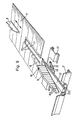
- the preparation base (7) is preferably inserted and pulled out in a frame (16) forming sliding guides (15).
- the preparation floor (7) below the one or more crop distributors (9, 10) in the inserted position with its length-end region (7a) forming the crop feed can be inserted with a slot guide (17) around the drive means (18) of each crop distributor (9, 10) and provided extractable.
- One or two or more material distributors (9, 10) can be assigned to the preparation base (7), these material distributors (9) being formed by rotating paddle wheels (FIG. 2) or the material distributors (10) being formed by pivotable guide plates (FIG. 3) .
- Each distributor (9, 10) is provided so that it can be rotated or pivoted about an axis (18) as the drive means.
- a preparation tray (7) or two or more preparation trays (7) can be held removably in the frame (16), which depends on the size of the combine harvester.
- Fig. 4 two preparation trays (7) are mounted next to one another in a frame (16) so that they can be pulled out, and these two preparation trays (7) are assigned three material distributors (10) formed by baffles.
- the sliding guides (15) are formed by upright flow guides (8) fixed on the frame (16) in the form of guide plates extending over the entire length of the preparation floor and sealing strips (19) attached to them, and the preparation floor (7) engages with strips (20) fastened on its long sides under the sealing strips (19) in a sealed manner.
- a flow guide (8) formed by a guide plate is also fastened in the central longitudinal region of each preparation tray (7) and runs in the longitudinal direction of the preparation tray (7) and ends at a distance from the material distributor (9, 10).
- the middle current guide (8) running in the longitudinal joint area of both preparation trays (7) forms two sliding guides (15) with two sealing strips (19).
- the frame (16) is stiffened by a plurality of cross struts (21) and the upright, axis-shaped drive means (18) engage by a cross strut (21).
- the slot guide (17) is formed by the slot and edged sliding strips (17a) and the insertion guide (22) is formed by a profile with two insertion channels (22a) of U-shaped or J-type cross section for the sliding strips (17a).
- the insertion guide (22) has inlet bevels (22b) for easy insertion of the preparation base (7) with its slot guide (17).
- the material distributors (10) formed by guide plates preferably have sawtooth-like drivers (10a) on both long sides, by means of which the material to be screened has an improved thrust effect against the preparation floor inclination.
- All guide plates (10) of one or more preparation trays (7) are adjusted automatically by a hydraulic control device (23) depending on the incline of the combine harvester (2) and thus the preparation tray (7).
- This control device (23) has a control unit (26) which is pivotably suspended on a support arm (24) which is fastened to a component (25) of the combine harvester and which is operated by two pressure medium cylinders (27, 28) with their piston rods (29, 30) is supported on the combine component (25), the pressure medium cylinder (27, 28) being pivotable on the Control unit (26) and the piston rods (29, 30) are pivotally mounted on the combine component (25).
- the two pressure chambers of the pressure medium cylinder (27) can be acted upon via hydraulic lines (31, 32) by a control valve (33), which is connected via lines (34, 35) to a pressure medium reservoir, not shown.
- a pendulum (36) is provided within the control unit (26).
- the control valve (33) is acted on such that it pressurizes the corresponding hydraulic line (31, 32) with the pressure medium until the cylinder (27) engages Control unit (26) has pivoted into a parallel position to the pendulum (36).
- the piston rod (29) is extended or retracted and, analogously, the second cylinder (28) is actuated by retracting or extending its piston rod (30).
- This pressure medium cylinder (28) is connected via two pressure medium lines (37, 38) to a third pressure medium cylinder (39), which is arranged below the preparation floor (7) and whose piston rod (40) engages a linkage (41) which is connected to the Drive axes (18) of the guide plates (10) is connected.
- the rotating material distributors (9) can also be rotated by means of such a control device (23), but can also be set in rotation in a different manner by a motor.
- Each preparation shelf (7) can be pulled out of the frame (16) in a few simple steps for cleaning purposes, with the slot guide (17) encompassing the drive axles (18) not requiring disassembly between the drive axles (18) and linkage (41), but rather the preparation shelf (7) can easily be pulled out from among the distributors (9, 10) and inserted again.
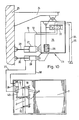
- 11 and 12 show an automatic adjustment of the driver's seat (42) within the driver's cab (43) of the combine harvester (2), this adjustment also being carried out by the control device (23) depending on the incline of the combine harvester.
- the driver's seat (42) is mounted on the frame (45) of the driver's cabin (43) about a horizontal swivel axis (44) and the control panel (46) is on the driver's seat (42) set, which is also pivoted with the driver's seat (42).
- a pressure medium cylinder (47) is pivotally mounted in the frame (45), the piston rod (48) of which engages a pivot lever (49) connected to the driver's seat (42) and which is connected to the control device (23) via pressure medium lines.
- the piston rod (48) is extended or retracted in accordance with the combine tendency and the seat (42) with the control panel (46) is pivoted about the axis (44), so that the seat (42) is also at an inclined position the driver's cabin (43), as shown in Fig. 12, is always brought into the horizontal position or held in this.
- each preparation tray (7) is assigned a medium crop distributor (9, 10) and in the abutting longitudinal edge region of the two preparation trays (7) there is a medium crop distributor (9 , 10), the drive means (18) of recessed edge areas (17b) of the preparation floors (7) is formed to form a slot guide (17).
- the control panel (46) can be arranged separately or connected to the driver's seat (42).
Landscapes
- Life Sciences & Earth Sciences (AREA)
- Environmental Sciences (AREA)
- Harvester Elements (AREA)
- Threshing Machine Elements (AREA)
Applications Claiming Priority (2)
| Application Number | Priority Date | Filing Date | Title |
|---|---|---|---|
| DE4016878 | 1990-05-25 | ||
| DE4016878A DE4016878A1 (de) | 1990-05-25 | 1990-05-25 | Vorrichtung zur gleichmaessigen gutverteilung bei maehdreschern |
Publications (3)
| Publication Number | Publication Date |
|---|---|
| EP0459109A2 true EP0459109A2 (fr) | 1991-12-04 |
| EP0459109A3 EP0459109A3 (en) | 1992-03-04 |
| EP0459109B1 EP0459109B1 (fr) | 1994-09-14 |
Family
ID=6407184
Family Applications (1)
| Application Number | Title | Priority Date | Filing Date |
|---|---|---|---|
| EP91105402A Expired - Lifetime EP0459109B1 (fr) | 1990-05-25 | 1991-04-05 | Appareil pour la répartition uniforme de produits dans une moissonneuse-batteuse |
Country Status (2)
| Country | Link |
|---|---|
| EP (1) | EP0459109B1 (fr) |
| DE (2) | DE4016878A1 (fr) |
Cited By (5)
| Publication number | Priority date | Publication date | Assignee | Title |
|---|---|---|---|---|
| US7572180B2 (en) | 2007-02-13 | 2009-08-11 | Cnh America Llc | Distribution leveling for an agricultural combine |
| EP2591661A1 (fr) * | 2011-11-09 | 2013-05-15 | CNH Belgium N.V. | Système de contrôle de distribution de moissonneuse agricole |
| EP2606712A1 (fr) * | 2011-12-21 | 2013-06-26 | CNH Belgium N.V. | Lit de vis sans fin pour système de nettoyage de nivellement latéral |
| CN104137696A (zh) * | 2013-05-10 | 2014-11-12 | 爱科公司 | 用于均匀分配农作物的方法 |
| CN113016367A (zh) * | 2021-04-23 | 2021-06-25 | 阿维斯汀农业机械(苏州)有限公司 | 一种谷物双重过滤装置 |
Families Citing this family (9)
| Publication number | Priority date | Publication date | Assignee | Title |
|---|---|---|---|---|
| DE4201412A1 (de) * | 1992-01-21 | 1993-07-22 | Martin Philipp | Einrichtung an einem kraftfahrzeug zur bequemen und sicheren kurvenfahrt durch selbsttaetigen fliehkraftausgleich |
| DE4207880A1 (de) * | 1992-03-12 | 1993-09-16 | Guenter Schulze | Aktives fahrer - sitz - system |
| GB202212331D0 (en) * | 2022-08-24 | 2022-10-05 | Agco Int Gmbh | A grain cleaning apparatus for a combine harvester |
| USD1031792S1 (en) | 2022-08-30 | 2024-06-18 | Calmer Holding Company, Llc | Round bar concave |
| USD1031791S1 (en) | 2022-08-30 | 2024-06-18 | Calmer Holding Company, Llc | Straight bar concave |
| USD1031793S1 (en) | 2022-08-30 | 2024-06-18 | Calmer Holding Company, Llc | Separating grate |
| US11877538B1 (en) | 2022-08-30 | 2024-01-23 | Calmer Holding Company, Llc | Threshing grains and legumes utilizing concaves with adjustable openings |
| USD1032666S1 (en) | 2022-08-30 | 2024-06-25 | Calmer Holding Company, Llc | MOG limiting subassembly for combine concave |
| USD1058613S1 (en) | 2022-11-29 | 2025-01-21 | Calmer Holding Company, Llc | Limiter plates |
Family Cites Families (16)
| Publication number | Priority date | Publication date | Assignee | Title |
|---|---|---|---|---|
| DE1937835B1 (de) * | 1969-07-25 | 1970-04-30 | Deere & Co | Anordnung des Zufuehrbodens von Dreschmaschinen und Maehdreschern |
| DE2013289B1 (fr) * | 1970-03-20 | 1971-04-22 | ||
| US3913589A (en) * | 1973-02-08 | 1975-10-21 | Int Harvester Co | Grain pan bottom door |
| DE2442766C3 (de) * | 1974-09-06 | 1982-01-28 | Georg 7341 Schalkstetten Hagmeier | Fahrzeugsitz, insbesondere Schleppersitz |
| FI750331A7 (fr) * | 1975-02-06 | 1976-08-07 | Rauma Repola Oy | |
| DE2525715C3 (de) * | 1975-06-10 | 1980-03-20 | Deere & Co., Moline, Ill. (V.St.A.), Niederlassung Deere & Co. European Office, 6800 Mannheim | Mähdrescher |
| SE7603120L (sv) * | 1976-03-09 | 1977-09-10 | Ostbergs Fabriks Ab | Anordning vid forarsits pa terrenggaende arbetsfordon |
| DE2638240C3 (de) * | 1976-08-25 | 1981-06-11 | Gebr.Claas Maschinenfabrik GmbH, 4834 Harsewinkel | Mähdrescher mit Förderboden |
| DE2805842A1 (de) * | 1978-02-11 | 1979-08-16 | Herbert Dr Ing Schnauber | Fahrzeugsitz mit einer vorrichtung zur anpassung an unterschiedliche koerpergewichte |
| DE2851777A1 (de) * | 1978-11-30 | 1980-07-17 | Claas Ohg | Selbstfahrende erntemaschine, insbesondere selbstfahrender maehdrescher |
| DE3008385C2 (de) * | 1980-03-05 | 1985-07-18 | Claas Ohg, 4834 Harsewinkel | Vorrichtung zum Verteilen von Siebgut |
| IT1159988B (it) * | 1983-11-30 | 1987-03-04 | Laverda Spa Pietro | Perfezionamenti alle macchine mietitrebbiatrici |
| DE8800121U1 (de) * | 1988-01-08 | 1988-02-18 | Huning-Wesseler, Walter, 49326 Melle | Sieb- und Fördereinrichtung |
| DE8804062U1 (de) * | 1988-03-25 | 1988-05-05 | Huning-Wesseler, Walter, 4520 Melle | Sieb- und Fördereinrichtung |
| DE3822689A1 (de) * | 1988-07-05 | 1990-01-11 | Deere & Co | Foerdervorrichtung |
| DE3839165C1 (en) * | 1988-11-19 | 1989-12-28 | Grammer Sitzsysteme Gmbh, 8450 Amberg, De | Driver's seat |
-
1990
- 1990-05-25 DE DE4016878A patent/DE4016878A1/de not_active Withdrawn
-
1991
- 1991-04-05 EP EP91105402A patent/EP0459109B1/fr not_active Expired - Lifetime
- 1991-04-05 DE DE59102900T patent/DE59102900D1/de not_active Expired - Fee Related
Cited By (8)
| Publication number | Priority date | Publication date | Assignee | Title |
|---|---|---|---|---|
| US7572180B2 (en) | 2007-02-13 | 2009-08-11 | Cnh America Llc | Distribution leveling for an agricultural combine |
| US7771260B2 (en) | 2007-02-13 | 2010-08-10 | Cnh America Llc | Distribution leveling for an agricultural combine |
| EP2591661A1 (fr) * | 2011-11-09 | 2013-05-15 | CNH Belgium N.V. | Système de contrôle de distribution de moissonneuse agricole |
| US9814184B2 (en) | 2011-11-09 | 2017-11-14 | Cnh Industrial America Llc | Crop material flow control system |
| EP2606712A1 (fr) * | 2011-12-21 | 2013-06-26 | CNH Belgium N.V. | Lit de vis sans fin pour système de nettoyage de nivellement latéral |
| US8777706B2 (en) | 2011-12-21 | 2014-07-15 | Cnh Industrial America Llc | Auger bed for a lateral leveling cleaning system |
| CN104137696A (zh) * | 2013-05-10 | 2014-11-12 | 爱科公司 | 用于均匀分配农作物的方法 |
| CN113016367A (zh) * | 2021-04-23 | 2021-06-25 | 阿维斯汀农业机械(苏州)有限公司 | 一种谷物双重过滤装置 |
Also Published As
| Publication number | Publication date |
|---|---|
| EP0459109B1 (fr) | 1994-09-14 |
| DE59102900D1 (de) | 1994-10-20 |
| EP0459109A3 (en) | 1992-03-04 |
| DE4016878A1 (de) | 1991-11-28 |
Similar Documents
| Publication | Publication Date | Title |
|---|---|---|
| DE60013249T2 (de) | Anpassungsfähigkeit bei axialflussmähdreschern | |
| EP0459109B1 (fr) | Appareil pour la répartition uniforme de produits dans une moissonneuse-batteuse | |
| DE2405207C3 (de) | Mähdrescher mit einer ein Spreusieb enthaltenden Reinigungsvorrichtung | |
| AT401596B (de) | Siebvorrichtung für einen mähdrescher, insbesondere für einen versuchsfeldmähdrescher | |
| DE1816165A1 (de) | Fahrbare Siebanlage | |
| EP0155556A2 (fr) | Dispositif pour l'aspiration de l'air dans les appareils de blutage ou classement | |
| DE3617872C2 (de) | Vorrichtung zum Flüssigkeitsentzug aus Suspensionen | |
| DE2954406C2 (fr) | ||
| DE2533274A1 (de) | Kombinierte maschine fuer koerniges gut, insbesondere getreidegut, die zum selektionieren durch schwerkraft und zum entsteinen im trockenverfahren dient | |
| DE102010050616A1 (de) | Kartoffellegevorrichtung | |
| DE2037447A1 (de) | Vorrichtung zur schnellen Entleerung großer Kornbehälter in Mähdreschern Arim Clayson N V, Zeäelgem (Belgien) | |
| EP1764163B1 (fr) | Tamis à étoiles avec dispositif de nettoyage | |
| DE3225645A1 (de) | Verfahren und einrichtung zum dosierten auftragen eines fluessigen bindemittels auf eine strassenflaeche | |
| DE1131162B (de) | Siebrost | |
| DD151252A5 (de) | Schuettlerloser selbstfahrender maehdrescher | |
| EP0103831A2 (fr) | Dispositif de criblage, notamment pour matières difficiles à cribler | |
| EP0077416A1 (fr) | Table à grain pour moissonneuses | |
| EP3383161B1 (fr) | Système de distribution | |
| DE1945077B2 (de) | Streugerät für körniges oder pulveriges Streugut | |
| DE841244C (de) | Maschine zum Ausstreuen von Pulver, insbesondere von pulverigen Pflanzenschutzmitteln | |
| DE929219C (de) | Vorrichtung zum Aussichten von Koernern von annaehernd kugeliger Gestalt mittels eines Foerderbandes | |
| EP4736619A1 (fr) | Machine de distribution agricole dotée d'un système de réservoir modulaire | |
| WO2026078098A1 (fr) | Dispositif de ramassage et système de ramassage | |
| DE60004647T2 (de) | Kohlenförderer | |
| DE102024129576A1 (de) | Aufsammelvorrichtung und Aufsammelsystem |
Legal Events
| Date | Code | Title | Description |
|---|---|---|---|
| PUAI | Public reference made under article 153(3) epc to a published international application that has entered the european phase |
Free format text: ORIGINAL CODE: 0009012 |
|
| AK | Designated contracting states |
Kind code of ref document: A2 Designated state(s): BE DE FR GB |
|
| PUAL | Search report despatched |
Free format text: ORIGINAL CODE: 0009013 |
|
| 17P | Request for examination filed |
Effective date: 19911122 |
|
| AK | Designated contracting states |
Kind code of ref document: A3 Designated state(s): BE DE FR GB |
|
| 17Q | First examination report despatched |
Effective date: 19921210 |
|
| GRAA | (expected) grant |
Free format text: ORIGINAL CODE: 0009210 |
|
| AK | Designated contracting states |
Kind code of ref document: B1 Designated state(s): BE DE FR GB |
|
| PG25 | Lapsed in a contracting state [announced via postgrant information from national office to epo] |
Ref country code: GB Effective date: 19940914 |
|
| REF | Corresponds to: |
Ref document number: 59102900 Country of ref document: DE Date of ref document: 19941020 |
|
| ET | Fr: translation filed | ||
| GBV | Gb: ep patent (uk) treated as always having been void in accordance with gb section 77(7)/1977 [no translation filed] |
Effective date: 19940914 |
|
| PLBE | No opposition filed within time limit |
Free format text: ORIGINAL CODE: 0009261 |
|
| STAA | Information on the status of an ep patent application or granted ep patent |
Free format text: STATUS: NO OPPOSITION FILED WITHIN TIME LIMIT |
|
| 26N | No opposition filed | ||
| PGFP | Annual fee paid to national office [announced via postgrant information from national office to epo] |
Ref country code: DE Payment date: 19990319 Year of fee payment: 9 |
|
| PGFP | Annual fee paid to national office [announced via postgrant information from national office to epo] |
Ref country code: BE Payment date: 19990422 Year of fee payment: 9 |
|
| PGFP | Annual fee paid to national office [announced via postgrant information from national office to epo] |
Ref country code: FR Payment date: 19990427 Year of fee payment: 9 |
|
| PG25 | Lapsed in a contracting state [announced via postgrant information from national office to epo] |
Ref country code: BE Free format text: LAPSE BECAUSE OF NON-PAYMENT OF DUE FEES Effective date: 20000430 |
|
| BERE | Be: lapsed |
Owner name: CLAAS OHG Effective date: 20000430 |
|
| PG25 | Lapsed in a contracting state [announced via postgrant information from national office to epo] |
Ref country code: FR Free format text: LAPSE BECAUSE OF NON-PAYMENT OF DUE FEES Effective date: 20001229 |
|
| PG25 | Lapsed in a contracting state [announced via postgrant information from national office to epo] |
Ref country code: DE Free format text: LAPSE BECAUSE OF NON-PAYMENT OF DUE FEES Effective date: 20010201 |
|
| REG | Reference to a national code |
Ref country code: FR Ref legal event code: ST |