EP0459183A1 - Transmetteur de commande - Google Patents
Transmetteur de commande Download PDFInfo
- Publication number
- EP0459183A1 EP0459183A1 EP19910107375 EP91107375A EP0459183A1 EP 0459183 A1 EP0459183 A1 EP 0459183A1 EP 19910107375 EP19910107375 EP 19910107375 EP 91107375 A EP91107375 A EP 91107375A EP 0459183 A1 EP0459183 A1 EP 0459183A1
- Authority
- EP
- European Patent Office
- Prior art keywords
- control
- housing
- transmitter according
- shift rod
- control transmitter
- Prior art date
- Legal status (The legal status is an assumption and is not a legal conclusion. Google has not performed a legal analysis and makes no representation as to the accuracy of the status listed.)
- Granted
Links
- 230000006835 compression Effects 0.000 description 2
- 238000007906 compression Methods 0.000 description 2
- 238000010276 construction Methods 0.000 description 1
- 230000000694 effects Effects 0.000 description 1
- 238000005516 engineering process Methods 0.000 description 1
- 238000000034 method Methods 0.000 description 1
- 230000035945 sensitivity Effects 0.000 description 1
Images


Classifications
-
- G—PHYSICS
- G05—CONTROLLING; REGULATING
- G05G—CONTROL DEVICES OR SYSTEMS INSOFAR AS CHARACTERISED BY MECHANICAL FEATURES ONLY
- G05G5/00—Means for preventing, limiting or returning the movements of parts of a control mechanism, e.g. locking controlling member
- G05G5/03—Means for enhancing the operator's awareness of arrival of the controlling member at a command or datum position; Providing feel, e.g. means for creating a counterforce
-
- G—PHYSICS
- G05—CONTROLLING; REGULATING
- G05G—CONTROL DEVICES OR SYSTEMS INSOFAR AS CHARACTERISED BY MECHANICAL FEATURES ONLY
- G05G9/00—Manually-actuated control mechanisms provided with one single controlling member co-operating with two or more controlled members, e.g. selectively, simultaneously
- G05G9/02—Manually-actuated control mechanisms provided with one single controlling member co-operating with two or more controlled members, e.g. selectively, simultaneously the controlling member being movable in different independent ways, movement in each individual way actuating one controlled member only
- G05G9/04—Manually-actuated control mechanisms provided with one single controlling member co-operating with two or more controlled members, e.g. selectively, simultaneously the controlling member being movable in different independent ways, movement in each individual way actuating one controlled member only in which movement in two or more ways can occur simultaneously
- G05G9/047—Manually-actuated control mechanisms provided with one single controlling member co-operating with two or more controlled members, e.g. selectively, simultaneously the controlling member being movable in different independent ways, movement in each individual way actuating one controlled member only in which movement in two or more ways can occur simultaneously the controlling member being movable by hand about orthogonal axes, e.g. joysticks
- G05G2009/04703—Mounting of controlling member
- G05G2009/04707—Mounting of controlling member with ball joint
-
- G—PHYSICS
- G05—CONTROLLING; REGULATING
- G05G—CONTROL DEVICES OR SYSTEMS INSOFAR AS CHARACTERISED BY MECHANICAL FEATURES ONLY
- G05G9/00—Manually-actuated control mechanisms provided with one single controlling member co-operating with two or more controlled members, e.g. selectively, simultaneously
- G05G9/02—Manually-actuated control mechanisms provided with one single controlling member co-operating with two or more controlled members, e.g. selectively, simultaneously the controlling member being movable in different independent ways, movement in each individual way actuating one controlled member only
- G05G9/04—Manually-actuated control mechanisms provided with one single controlling member co-operating with two or more controlled members, e.g. selectively, simultaneously the controlling member being movable in different independent ways, movement in each individual way actuating one controlled member only in which movement in two or more ways can occur simultaneously
- G05G9/047—Manually-actuated control mechanisms provided with one single controlling member co-operating with two or more controlled members, e.g. selectively, simultaneously the controlling member being movable in different independent ways, movement in each individual way actuating one controlled member only in which movement in two or more ways can occur simultaneously the controlling member being movable by hand about orthogonal axes, e.g. joysticks
- G05G2009/0474—Manually-actuated control mechanisms provided with one single controlling member co-operating with two or more controlled members, e.g. selectively, simultaneously the controlling member being movable in different independent ways, movement in each individual way actuating one controlled member only in which movement in two or more ways can occur simultaneously the controlling member being movable by hand about orthogonal axes, e.g. joysticks characterised by means converting mechanical movement into electric signals
- G05G2009/04748—Position sensor for rotary movement, e.g. potentiometer
-
- G—PHYSICS
- G05—CONTROLLING; REGULATING
- G05G—CONTROL DEVICES OR SYSTEMS INSOFAR AS CHARACTERISED BY MECHANICAL FEATURES ONLY
- G05G9/00—Manually-actuated control mechanisms provided with one single controlling member co-operating with two or more controlled members, e.g. selectively, simultaneously
- G05G9/02—Manually-actuated control mechanisms provided with one single controlling member co-operating with two or more controlled members, e.g. selectively, simultaneously the controlling member being movable in different independent ways, movement in each individual way actuating one controlled member only
- G05G9/04—Manually-actuated control mechanisms provided with one single controlling member co-operating with two or more controlled members, e.g. selectively, simultaneously the controlling member being movable in different independent ways, movement in each individual way actuating one controlled member only in which movement in two or more ways can occur simultaneously
- G05G9/047—Manually-actuated control mechanisms provided with one single controlling member co-operating with two or more controlled members, e.g. selectively, simultaneously the controlling member being movable in different independent ways, movement in each individual way actuating one controlled member only in which movement in two or more ways can occur simultaneously the controlling member being movable by hand about orthogonal axes, e.g. joysticks
- G05G2009/04766—Manually-actuated control mechanisms provided with one single controlling member co-operating with two or more controlled members, e.g. selectively, simultaneously the controlling member being movable in different independent ways, movement in each individual way actuating one controlled member only in which movement in two or more ways can occur simultaneously the controlling member being movable by hand about orthogonal axes, e.g. joysticks providing feel, e.g. indexing means, means to create counterforce
- G05G2009/0477—Manually-actuated control mechanisms provided with one single controlling member co-operating with two or more controlled members, e.g. selectively, simultaneously the controlling member being movable in different independent ways, movement in each individual way actuating one controlled member only in which movement in two or more ways can occur simultaneously the controlling member being movable by hand about orthogonal axes, e.g. joysticks providing feel, e.g. indexing means, means to create counterforce holding the member in a number of definite positions
-
- Y—GENERAL TAGGING OF NEW TECHNOLOGICAL DEVELOPMENTS; GENERAL TAGGING OF CROSS-SECTIONAL TECHNOLOGIES SPANNING OVER SEVERAL SECTIONS OF THE IPC; TECHNICAL SUBJECTS COVERED BY FORMER USPC CROSS-REFERENCE ART COLLECTIONS [XRACs] AND DIGESTS
- Y10—TECHNICAL SUBJECTS COVERED BY FORMER USPC
- Y10T—TECHNICAL SUBJECTS COVERED BY FORMER US CLASSIFICATION
- Y10T74/00—Machine element or mechanism
- Y10T74/20—Control lever and linkage systems
- Y10T74/20012—Multiple controlled elements
- Y10T74/20201—Control moves in two planes
-
- Y—GENERAL TAGGING OF NEW TECHNOLOGICAL DEVELOPMENTS; GENERAL TAGGING OF CROSS-SECTIONAL TECHNOLOGIES SPANNING OVER SEVERAL SECTIONS OF THE IPC; TECHNICAL SUBJECTS COVERED BY FORMER USPC CROSS-REFERENCE ART COLLECTIONS [XRACs] AND DIGESTS
- Y10—TECHNICAL SUBJECTS COVERED BY FORMER USPC
- Y10T—TECHNICAL SUBJECTS COVERED BY FORMER US CLASSIFICATION
- Y10T74/00—Machine element or mechanism
- Y10T74/20—Control lever and linkage systems
- Y10T74/20576—Elements
- Y10T74/20636—Detents
Definitions
- the invention relates to a control transmitter according to the preamble of the main claim.
- Such known control transmitters are probably simple in construction, but no longer meet the requirements for a more advanced technology.
- control transmitter according to the invention with the characterizing features of the main claim has the advantage that it brings a significant improvement in function with only slightly higher effort and is therefore particularly well suited for special cases.
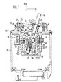
- FIG. 1 a longitudinal section through a control transmitter
- FIGS. 2A to 2D an individual part in the different views (locking plate)
- FIG. 3 a section through a housing part
- FIG. 4 a plan view of the housing part according to FIG. 3
- FIG. 5 a side view of the control transmitter
- FIG. 6 an application for the control transmitter.
- 10 denotes the approximately cup-shaped housing of a control transmitter, on the open upper part of which a control housing 11 is arranged, which in turn is closed by a link 12.
- the control housing 11 has an open extension 13 with a square cross section, which projects far into the housing 10 and on the lower side of which a locking plate 14 is fastened.
- the backdrop 12 there is a backdrop 15 for a shift rod 16 which projects into the housing to the end of the extension 13, i. H. to the locking plate 14.
- the shift rod 16 is mounted in a ball joint 17, which is part of a funnel-like extension 18 which extends downwards, ie. H. to the locking plate 14 approximately conically narrowed and ends in the ball joint 17.
- the shape of the extension 18 is strongly conical and slightly curved in the lower part 18A, which then follows upwards to an annular groove-like recess 18B, which is followed by a region 18C which is again strongly conical, which then flattens out and in a cylindrical end part 18D ends.
- the entire contour described is circular.
- the part of the shift rod located below the ball joint 17 is in operative connection with two deflection brackets 24, 25, which are pivotably mounted in the extension 13 of the control housing 11 at right angles to one another. Only the control bracket 24 is described, since the control bracket 25 is designed and mounted in the same way.
- the pin 27 of a rotary angle sensor 28 (potentiometer) is mounted, the pin 27 being followed by a further pin 32 with a much smaller diameter, which projects into the control housing, specifically into the space between the extension 13 and the extension 18.
- the pin 32 has a flattened area 29, against which a pin 30 rests, which is inserted into a bore 31 of the bracket 24.
- the control bracket 24 has a longitudinal slot 36 through which the lower part 16A of the shift rod passes.
- a slide bush 37 is mounted on the shift rod, which is fixed on both sides by snap rings 38.
- a pressure pin 39 protrudes with its shaft 40 into a longitudinal bore 41 of the shift rod, in which a pressure spring 42 is arranged, which presses the pressure pin 39 against the locking plate 14, which is discussed further below.
- the control bracket 25 is designed in exactly the same way as the control bracket 24. Through its longitudinal slot 44, which corresponds to the longitudinal slot 36 in the switching bracket 24, the switching lever 16 penetrates this control bracket in the region of the sliding bush 37. The switching lever 16 is bound in this sliding bracket around the spherical plain bearing 17 pivotable in a plane X, which runs perpendicular to the plane Y.
- the latching plate 14 for which reference is also made to FIGS. 2a to 2d, has in its center and facing the shift rod a surface 46 which is part of a spherical surface, the center of which lies in the axis of the shift rod 16 when the latter is in a precisely vertical central position located.
- the surface 46 extends far outwards and has a square shape as seen from above - see FIG. 2C. It ends at an all-round and sloping edge 47, which in turn merges into an outer surface 48, which also has a spherical surface shape and runs centrally to surface 46. Diagonal grooves 49 extend from the corner points of surface 46. It should also be noted that the locking plate 14 is of course firmly arranged on the extension 13 of the control housing 11.
- a rubber hood 50 is attached between the link 12 and the control housing 11 and covers the entire control transmitter in a sealed manner towards the switching rod 16.
- the setting 12 is connected to the control part 11 by means of screws 51.
- a cable harness plug 53 is installed in the lower opening 52 of the housing 10, as shown in FIG.
- the two potentiometers - of which only the potentiometer 28 is shown - are adjustable from the outside. For this purpose, reference is made to FIGS. 3 and 4.
- a knurled nut 54 is located in a flange of the housing, with the aid of which the potentiometer 28 can be set to a specific desired value. With a second knurled nut 55, the rotary angle sensor actuated by the control bracket 25 can be adjusted.
- the control transmitter according to the invention is particularly suitable for actuating two proportional magnets 57, 58 of a directional control valve 59, with the aid of which a working cylinder 60 is controlled, see FIG. 6.
- the control transmitter or the switching rod 16 can be deflected simultaneously in the directions of the two main axes X, Y.
- the slide 19 slides along the shift rod and with its outer contour on the curved conical contour 18A to 18C of the control housing 11.
- the steep edge 18C is formed, so that when a certain deflection angle in the X or Y direction is reached, the actuating force increases due to the increased frictional force on Slider is achieved. This means that the person operating the device has a good feeling for the size of the deflection.
- the speed of the hydraulic actuators - in this case the working cylinder - is optimally adapted to the respective different work processes.
- the setting option is achieved via the rotary encoder.
- the change in resistance causes a change in the sensitivity of the electronics, which has an effect on the size of the electrical current for controlling the proportional valves 57 and 58 at a certain deflection angle of the shift rod, which is decisive for the deflection of the control slide in the directional control valve and thus for the volume flow in the working cylinder 60 .
- the arrangement of the two potentiometers is selected so that a secure assignment for both axes is guaranteed and unintentional adjustment is avoided.
- the potentiometers are set via the knurled disks 54, 55 - see FIGS. 3 and 4.
- the control transmitter After reaching or exceeding a certain deflection angle of the shift rod, the control transmitter should remain deflected at this certain angle after release of the same (detent position) and only be brought out of this detent position with an increased force applied in the direction of the rest position. This is achieved with the aid of the locking plate 14 and the pressure pin 39.
- the pressure pin slides from the inner spherical surface 46 to the outer spherical surface 48 when a certain deflection angle of the shift rod is reached or exceeded.
- the prestressing of the pressure bolt 39 is sufficient to compensate for the restoring forces of the spring 20 counteract via the slider 19. When the specific deflection angle is exceeded in both axes, the pressure pin is guided and held in this position by the grooves 49 on the locking plate.
Landscapes
- Physics & Mathematics (AREA)
- General Physics & Mathematics (AREA)
- Engineering & Computer Science (AREA)
- Automation & Control Theory (AREA)
- Mechanical Control Devices (AREA)
- Servomotors (AREA)
- Gear-Shifting Mechanisms (AREA)
- Operation Control Of Excavators (AREA)
- Control Of Position Or Direction (AREA)
Applications Claiming Priority (2)
| Application Number | Priority Date | Filing Date | Title |
|---|---|---|---|
| DE4017696 | 1990-06-01 | ||
| DE4017696A DE4017696A1 (de) | 1990-06-01 | 1990-06-01 | Steuergeber |
Publications (2)
| Publication Number | Publication Date |
|---|---|
| EP0459183A1 true EP0459183A1 (fr) | 1991-12-04 |
| EP0459183B1 EP0459183B1 (fr) | 1993-12-29 |
Family
ID=6407634
Family Applications (1)
| Application Number | Title | Priority Date | Filing Date |
|---|---|---|---|
| EP91107375A Expired - Lifetime EP0459183B1 (fr) | 1990-06-01 | 1991-05-07 | Transmetteur de commande |
Country Status (4)
| Country | Link |
|---|---|
| US (1) | US5176041A (fr) |
| EP (1) | EP0459183B1 (fr) |
| DE (2) | DE4017696A1 (fr) |
| ES (1) | ES2048527T3 (fr) |
Cited By (9)
| Publication number | Priority date | Publication date | Assignee | Title |
|---|---|---|---|---|
| DE4306577C1 (de) * | 1993-03-03 | 1994-05-19 | Nbb Nachrichtentech Gmbh | Handsteuergerät mit einem Steuerknüppel |
| WO1998043144A1 (fr) * | 1997-03-21 | 1998-10-01 | Kvaerner Asa | Manette de commande et de manoeuvre |
| WO1999005060A1 (fr) * | 1997-07-25 | 1999-02-04 | Crown Equipment Corporation | Poignee de commande multifonction |
| US6082212A (en) * | 1997-07-25 | 2000-07-04 | Crown Equipment Corporation | Multi-function control handle |
| WO2000039654A2 (fr) | 1998-12-24 | 2000-07-06 | Mannesmann Rexroth Ag | Appareil de commande electrique actionne manuellement |
| DE19901038A1 (de) * | 1999-01-14 | 2000-11-23 | Robert Christl | Bedienungs-Einrichtung für operative Schalt-und-Regel-Steuerung |
| WO2005033821A2 (fr) | 2003-10-04 | 2005-04-14 | Bosch Rexroth Ag | Appareil de commande electrique a actionnement manuel |
| EP1801685A1 (fr) * | 2005-12-22 | 2007-06-27 | PENNY & GILES CONTROLS LIMITED | Manette de commande avec des moyens de maintien en position |
| EP2204719A1 (fr) * | 2009-01-05 | 2010-07-07 | Guillemot Corporation | Joystick à effet Hall, procédé de fabrication et manette correspondants |
Families Citing this family (19)
| Publication number | Priority date | Publication date | Assignee | Title |
|---|---|---|---|---|
| WO1994019735A1 (fr) * | 1993-02-20 | 1994-09-01 | Nbb Nachrichtentechnik Gmbh & Co. Kg | Appareil manuel de commande a levier de commande |
| JPH0685449U (ja) * | 1993-05-24 | 1994-12-06 | 株式会社小松製作所 | 排土板制御装置 |
| US5467108A (en) * | 1994-02-15 | 1995-11-14 | Lexmark International, Inc. | Adjustable pointing stick assembly |
| GB2341664B (en) * | 1996-05-18 | 2000-10-11 | Penny & Giles Controls Ltd | Electrical joystick controller |
| GB9610462D0 (en) * | 1996-05-18 | 1996-07-24 | Penny & Giles Electronic Compo | Electrical joystick controller |
| US5831554A (en) * | 1997-09-08 | 1998-11-03 | Joseph Pollak Corporation | Angular position sensor for pivoted control devices |
| JP3730439B2 (ja) * | 1999-04-22 | 2006-01-05 | アルプス電気株式会社 | 多方向入力装置 |
| US6634383B2 (en) | 2001-12-14 | 2003-10-21 | Caterpillar Inc. | Magnetic detent assist assembly |
| JP2005209442A (ja) * | 2004-01-21 | 2005-08-04 | Alps Electric Co Ltd | 多方向入力装置 |
| GB0503663D0 (en) * | 2005-02-23 | 2005-03-30 | Penny & Giles Controls Ltd | Joystick controller |
| EP2113819B1 (fr) * | 2008-05-02 | 2011-11-16 | Alps Electric Co., Ltd. | Appareil d'entrée directionnel multiple |
| US8991429B2 (en) * | 2009-02-05 | 2015-03-31 | Hitachi Construction Machinery Co., Ltd. | Pilot valve assembly |
| JP4810667B2 (ja) * | 2009-03-06 | 2011-11-09 | 栄通信工業株式会社 | ジョイスティックコントローラ |
| US20140251070A1 (en) * | 2013-03-08 | 2014-09-11 | Brenton Arthur Kornelson | Machine controller having joystick and adjustable hands-free locking mechanism |
| JP6167779B2 (ja) * | 2013-09-10 | 2017-07-26 | マツダ株式会社 | 車両用シフト装置 |
| DE102015008517A1 (de) * | 2014-07-10 | 2016-01-14 | Marquardt Gmbh | Stellglied, insbesondere für ein Kraftfahrzeug |
| WO2016176545A1 (fr) * | 2015-04-30 | 2016-11-03 | Oceaneering International, Inc. | Poignée souple à statisme nul |
| CA3214554A1 (fr) | 2021-04-08 | 2022-10-13 | David Anthony Cowling | Dispositif de commande mecanique a quatre axes |
| EP4553607A1 (fr) * | 2023-11-08 | 2025-05-14 | elobau GmbH & Co. KG | Élément de commande pour une machine |
Citations (6)
| Publication number | Priority date | Publication date | Assignee | Title |
|---|---|---|---|---|
| DE767337C (de) * | 1940-10-30 | 1952-05-29 | Raboma Maschinenfabrik Hermann | Kugelgelenkschalter |
| DE1031868B (de) * | 1953-10-30 | 1958-06-12 | Starkstrom Appbau G M B H | Kugelschalter |
| EP0043809A2 (fr) * | 1980-07-04 | 1982-01-13 | Hydrino Ab | Dispositif dans un levier multidirectionnel |
| DE3238048A1 (de) * | 1982-10-14 | 1984-04-19 | W. Gessmann GmbH, 7105 Leingarten | Verbundantrieb fuer schalt- oder stellglieder |
| US4587510A (en) * | 1983-10-19 | 1986-05-06 | Wico Corporation | Analog joystick controller |
| US4620176A (en) * | 1984-09-25 | 1986-10-28 | Hayes Charles L | Control stick mechanism |
Family Cites Families (8)
| Publication number | Priority date | Publication date | Assignee | Title |
|---|---|---|---|---|
| US2958233A (en) * | 1957-11-27 | 1960-11-01 | Thew Shovel Co | Valve indexing mechanism |
| US3827313A (en) * | 1973-01-24 | 1974-08-06 | Square D Co | Miniaturized joystick and cam structure with push button switch operating means |
| US3818154A (en) * | 1973-04-09 | 1974-06-18 | S Presentey | Joystick type controller for switches |
| GB1509101A (en) * | 1976-04-08 | 1978-04-26 | Slm Engs Ltd | Control devices for resolving angular movement |
| DE2916172C2 (de) * | 1979-04-21 | 1983-08-18 | Karl 7298 Loßburg Hehl | Proportionalventil für hydraulische Anlagen |
| US4325050A (en) * | 1980-12-08 | 1982-04-13 | Kraft Systems, Inc. | Control stick assembly |
| SE443672B (sv) * | 1982-12-23 | 1986-03-03 | Akermans Verkstad Ab | Styrspakanordning |
| FR2599185B1 (fr) * | 1986-05-22 | 1988-11-10 | Telemecanique Electrique | Manipulateur analogique a orientations privilegiees |
-
1990
- 1990-06-01 DE DE4017696A patent/DE4017696A1/de not_active Withdrawn
-
1991
- 1991-05-07 EP EP91107375A patent/EP0459183B1/fr not_active Expired - Lifetime
- 1991-05-07 ES ES91107375T patent/ES2048527T3/es not_active Expired - Lifetime
- 1991-05-07 DE DE91107375T patent/DE59100765D1/de not_active Expired - Fee Related
- 1991-05-13 US US07/699,459 patent/US5176041A/en not_active Expired - Fee Related
Patent Citations (6)
| Publication number | Priority date | Publication date | Assignee | Title |
|---|---|---|---|---|
| DE767337C (de) * | 1940-10-30 | 1952-05-29 | Raboma Maschinenfabrik Hermann | Kugelgelenkschalter |
| DE1031868B (de) * | 1953-10-30 | 1958-06-12 | Starkstrom Appbau G M B H | Kugelschalter |
| EP0043809A2 (fr) * | 1980-07-04 | 1982-01-13 | Hydrino Ab | Dispositif dans un levier multidirectionnel |
| DE3238048A1 (de) * | 1982-10-14 | 1984-04-19 | W. Gessmann GmbH, 7105 Leingarten | Verbundantrieb fuer schalt- oder stellglieder |
| US4587510A (en) * | 1983-10-19 | 1986-05-06 | Wico Corporation | Analog joystick controller |
| US4620176A (en) * | 1984-09-25 | 1986-10-28 | Hayes Charles L | Control stick mechanism |
Cited By (12)
| Publication number | Priority date | Publication date | Assignee | Title |
|---|---|---|---|---|
| DE4306577C1 (de) * | 1993-03-03 | 1994-05-19 | Nbb Nachrichtentech Gmbh | Handsteuergerät mit einem Steuerknüppel |
| US5680797A (en) * | 1993-03-03 | 1997-10-28 | Nbb Machrichtentechnik Gmbh & Co. Kg | Manual control appliance with a control lever |
| DE4306577C2 (de) * | 1993-03-03 | 1998-02-12 | Nbb Nachrichtentech Gmbh | Handsteuergerät mit einem Steuerknüppel |
| WO1998043144A1 (fr) * | 1997-03-21 | 1998-10-01 | Kvaerner Asa | Manette de commande et de manoeuvre |
| WO1999005060A1 (fr) * | 1997-07-25 | 1999-02-04 | Crown Equipment Corporation | Poignee de commande multifonction |
| US6082212A (en) * | 1997-07-25 | 2000-07-04 | Crown Equipment Corporation | Multi-function control handle |
| WO2000039654A2 (fr) | 1998-12-24 | 2000-07-06 | Mannesmann Rexroth Ag | Appareil de commande electrique actionne manuellement |
| DE19901038A1 (de) * | 1999-01-14 | 2000-11-23 | Robert Christl | Bedienungs-Einrichtung für operative Schalt-und-Regel-Steuerung |
| WO2005033821A2 (fr) | 2003-10-04 | 2005-04-14 | Bosch Rexroth Ag | Appareil de commande electrique a actionnement manuel |
| EP1801685A1 (fr) * | 2005-12-22 | 2007-06-27 | PENNY & GILES CONTROLS LIMITED | Manette de commande avec des moyens de maintien en position |
| US7544905B2 (en) | 2005-12-22 | 2009-06-09 | Penny & Giles Controls Limited | Joystick controller with put-and-stay capability |
| EP2204719A1 (fr) * | 2009-01-05 | 2010-07-07 | Guillemot Corporation | Joystick à effet Hall, procédé de fabrication et manette correspondants |
Also Published As
| Publication number | Publication date |
|---|---|
| DE4017696A1 (de) | 1991-12-05 |
| US5176041A (en) | 1993-01-05 |
| ES2048527T3 (es) | 1994-03-16 |
| DE59100765D1 (de) | 1994-02-10 |
| EP0459183B1 (fr) | 1993-12-29 |
Similar Documents
| Publication | Publication Date | Title |
|---|---|---|
| EP0459183B1 (fr) | Transmetteur de commande | |
| DE102008013280B4 (de) | Joystick mit einer Sensoreinrichtung | |
| DE3213034A1 (de) | Steuerung mit einem steuerhebel | |
| DE1295300B (de) | Steuergeraet mit zwei Freiheitsgraden mit einem in einem Universalgelenk gelagerten Steuerhebel | |
| DE29516531U1 (de) | Kniehebelspannvorrichtung | |
| DE10160801C2 (de) | Schalteinrichtung mit Rastbolzen, sowie Rastbolzen-Anordnung | |
| DE1673599A1 (de) | Einstellvorrichtung mit einem in bezug auf ein zugehoeriges Gehaeuse durch Drehung axial verschieblichen Einstellelement,insbesondere zur Einstellung von Vakuumreglern | |
| EP0683906A1 (fr) | Appareil manuel de commande a levier de commande. | |
| DE3117414C2 (de) | Steuergeber | |
| DE69305212T2 (de) | Fahrzeugfensterhebervorrichtung | |
| DE29701730U1 (de) | Kniehebelspannvorrichtung, insbesondere zur Verwendung in Vorrichtungen und Schweißmaschinen des Karosseriebaus der Kfz-Industrie | |
| DE3012765C2 (fr) | ||
| EP1462697B1 (fr) | Vanne actionnée pneumatiquement | |
| DE2615219A1 (de) | Abschaltventil fuer servolenkungen | |
| WO2000039654A2 (fr) | Appareil de commande electrique actionne manuellement | |
| DE3439453A1 (de) | Feinsteuervorrichtung | |
| DE9210096U1 (de) | Pneumatischer Stellantrieb | |
| EP0751020B1 (fr) | Dispositif de réglage à commande par câble, en particulier pour chauffage et ventilation de véhicule à moteur | |
| DE3246714C2 (de) | Elektrischer Schalter, insbesondere Lenkstockschalter für Kraftfahrzeuge | |
| DE3142450C2 (de) | Drehantrieb für einen Schließkörper | |
| DE2106808C3 (de) | Leistungsbegrenzungs-Einrichtung für hydrostatische Verstellpumpen | |
| EP1170511A2 (fr) | Dispositif de verrouillage | |
| DE69815595T2 (de) | Klemmvorrichtung | |
| DE19709925C2 (de) | Vorrichtung zur Übertragung einer Steuer- oder Schaltbewegung | |
| DE2704596A1 (de) | Elektrische steuermechanik |
Legal Events
| Date | Code | Title | Description |
|---|---|---|---|
| PUAI | Public reference made under article 153(3) epc to a published international application that has entered the european phase |
Free format text: ORIGINAL CODE: 0009012 |
|
| AK | Designated contracting states |
Kind code of ref document: A1 Designated state(s): DE ES FR GB IT |
|
| RAP3 | Party data changed (applicant data changed or rights of an application transferred) |
Owner name: ROBERT BOSCH GMBH |
|
| 17P | Request for examination filed |
Effective date: 19920502 |
|
| 17Q | First examination report despatched |
Effective date: 19930120 |
|
| GRAA | (expected) grant |
Free format text: ORIGINAL CODE: 0009210 |
|
| AK | Designated contracting states |
Kind code of ref document: B1 Designated state(s): DE ES FR GB IT |
|
| ET | Fr: translation filed | ||
| GBT | Gb: translation of ep patent filed (gb section 77(6)(a)/1977) |
Effective date: 19940111 |
|
| REF | Corresponds to: |
Ref document number: 59100765 Country of ref document: DE Date of ref document: 19940210 |
|
| REG | Reference to a national code |
Ref country code: ES Ref legal event code: FG2A Ref document number: 2048527 Country of ref document: ES Kind code of ref document: T3 |
|
| ITF | It: translation for a ep patent filed | ||
| PGFP | Annual fee paid to national office [announced via postgrant information from national office to epo] |
Ref country code: ES Payment date: 19940516 Year of fee payment: 4 |
|
| PGFP | Annual fee paid to national office [announced via postgrant information from national office to epo] |
Ref country code: FR Payment date: 19940530 Year of fee payment: 4 |
|
| PLBE | No opposition filed within time limit |
Free format text: ORIGINAL CODE: 0009261 |
|
| STAA | Information on the status of an ep patent application or granted ep patent |
Free format text: STATUS: NO OPPOSITION FILED WITHIN TIME LIMIT |
|
| 26N | No opposition filed | ||
| PG25 | Lapsed in a contracting state [announced via postgrant information from national office to epo] |
Ref country code: GB Effective date: 19950507 |
|
| PG25 | Lapsed in a contracting state [announced via postgrant information from national office to epo] |
Ref country code: ES Free format text: LAPSE BECAUSE OF NON-PAYMENT OF DUE FEES Effective date: 19950508 |
|
| GBPC | Gb: european patent ceased through non-payment of renewal fee |
Effective date: 19950507 |
|
| PG25 | Lapsed in a contracting state [announced via postgrant information from national office to epo] |
Ref country code: FR Effective date: 19960229 |
|
| REG | Reference to a national code |
Ref country code: FR Ref legal event code: ST |
|
| REG | Reference to a national code |
Ref country code: FR Ref legal event code: ST |
|
| REG | Reference to a national code |
Ref country code: ES Ref legal event code: FD2A Effective date: 19990405 |
|
| PG25 | Lapsed in a contracting state [announced via postgrant information from national office to epo] |
Ref country code: IT Free format text: LAPSE BECAUSE OF NON-PAYMENT OF DUE FEES;WARNING: LAPSES OF ITALIAN PATENTS WITH EFFECTIVE DATE BEFORE 2007 MAY HAVE OCCURRED AT ANY TIME BEFORE 2007. THE CORRECT EFFECTIVE DATE MAY BE DIFFERENT FROM THE ONE RECORDED. Effective date: 20050507 |
|
| PGFP | Annual fee paid to national office [announced via postgrant information from national office to epo] |
Ref country code: DE Payment date: 20060714 Year of fee payment: 16 |
|
| PG25 | Lapsed in a contracting state [announced via postgrant information from national office to epo] |
Ref country code: DE Free format text: LAPSE BECAUSE OF NON-PAYMENT OF DUE FEES Effective date: 20071201 |