EP0459219B1 - Arrangement pour fixer un profil de guidage de fenêtre - Google Patents
Arrangement pour fixer un profil de guidage de fenêtre Download PDFInfo
- Publication number
- EP0459219B1 EP0459219B1 EP91107852A EP91107852A EP0459219B1 EP 0459219 B1 EP0459219 B1 EP 0459219B1 EP 91107852 A EP91107852 A EP 91107852A EP 91107852 A EP91107852 A EP 91107852A EP 0459219 B1 EP0459219 B1 EP 0459219B1
- Authority
- EP
- European Patent Office
- Prior art keywords
- profile
- shaped
- windowpane
- door
- arrangement according
- Prior art date
- Legal status (The legal status is an assumption and is not a legal conclusion. Google has not performed a legal analysis and makes no representation as to the accuracy of the status listed.)
- Expired - Lifetime
Links
- 238000007789 sealing Methods 0.000 claims description 10
- 239000002184 metal Substances 0.000 claims description 3
- 230000002787 reinforcement Effects 0.000 claims description 3
- 241001074085 Scophthalmus aquosus Species 0.000 claims 6
- 210000003414 extremity Anatomy 0.000 claims 1
- 239000011796 hollow space material Substances 0.000 claims 1
- 210000003141 lower extremity Anatomy 0.000 claims 1
- 210000001364 upper extremity Anatomy 0.000 claims 1
- 230000006835 compression Effects 0.000 description 1
- 238000007906 compression Methods 0.000 description 1
Images
Classifications
-
- B—PERFORMING OPERATIONS; TRANSPORTING
- B60—VEHICLES IN GENERAL
- B60J—WINDOWS, WINDSCREENS, NON-FIXED ROOFS, DOORS, OR SIMILAR DEVICES FOR VEHICLES; REMOVABLE EXTERNAL PROTECTIVE COVERINGS SPECIALLY ADAPTED FOR VEHICLES
- B60J1/00—Windows; Windscreens; Accessories therefor
- B60J1/08—Windows; Windscreens; Accessories therefor arranged at vehicle sides
- B60J1/12—Windows; Windscreens; Accessories therefor arranged at vehicle sides adjustable
- B60J1/16—Windows; Windscreens; Accessories therefor arranged at vehicle sides adjustable slidable
- B60J1/17—Windows; Windscreens; Accessories therefor arranged at vehicle sides adjustable slidable vertically
-
- B—PERFORMING OPERATIONS; TRANSPORTING
- B60—VEHICLES IN GENERAL
- B60J—WINDOWS, WINDSCREENS, NON-FIXED ROOFS, DOORS, OR SIMILAR DEVICES FOR VEHICLES; REMOVABLE EXTERNAL PROTECTIVE COVERINGS SPECIALLY ADAPTED FOR VEHICLES
- B60J10/00—Sealing arrangements
- B60J10/20—Sealing arrangements characterised by the shape
- B60J10/24—Sealing arrangements characterised by the shape having tubular parts
- B60J10/248—Sealing arrangements characterised by the shape having tubular parts having two or more tubular cavities, e.g. formed by partition walls
-
- B—PERFORMING OPERATIONS; TRANSPORTING
- B60—VEHICLES IN GENERAL
- B60J—WINDOWS, WINDSCREENS, NON-FIXED ROOFS, DOORS, OR SIMILAR DEVICES FOR VEHICLES; REMOVABLE EXTERNAL PROTECTIVE COVERINGS SPECIALLY ADAPTED FOR VEHICLES
- B60J10/00—Sealing arrangements
- B60J10/30—Sealing arrangements characterised by the fastening means
-
- B—PERFORMING OPERATIONS; TRANSPORTING
- B60—VEHICLES IN GENERAL
- B60J—WINDOWS, WINDSCREENS, NON-FIXED ROOFS, DOORS, OR SIMILAR DEVICES FOR VEHICLES; REMOVABLE EXTERNAL PROTECTIVE COVERINGS SPECIALLY ADAPTED FOR VEHICLES
- B60J10/00—Sealing arrangements
- B60J10/70—Sealing arrangements specially adapted for windows or windscreens
- B60J10/74—Sealing arrangements specially adapted for windows or windscreens for sliding window panes, e.g. sash guides
- B60J10/76—Sealing arrangements specially adapted for windows or windscreens for sliding window panes, e.g. sash guides for window sashes; for glass run channels
-
- B—PERFORMING OPERATIONS; TRANSPORTING
- B60—VEHICLES IN GENERAL
- B60J—WINDOWS, WINDSCREENS, NON-FIXED ROOFS, DOORS, OR SIMILAR DEVICES FOR VEHICLES; REMOVABLE EXTERNAL PROTECTIVE COVERINGS SPECIALLY ADAPTED FOR VEHICLES
- B60J10/00—Sealing arrangements
- B60J10/70—Sealing arrangements specially adapted for windows or windscreens
- B60J10/74—Sealing arrangements specially adapted for windows or windscreens for sliding window panes, e.g. sash guides
- B60J10/79—Sealing arrangements specially adapted for windows or windscreens for sliding window panes, e.g. sash guides for flush-glass windows, i.e. for windows flush with the vehicle body or the window frame
-
- B—PERFORMING OPERATIONS; TRANSPORTING
- B60—VEHICLES IN GENERAL
- B60J—WINDOWS, WINDSCREENS, NON-FIXED ROOFS, DOORS, OR SIMILAR DEVICES FOR VEHICLES; REMOVABLE EXTERNAL PROTECTIVE COVERINGS SPECIALLY ADAPTED FOR VEHICLES
- B60J10/00—Sealing arrangements
- B60J10/80—Sealing arrangements specially adapted for opening panels, e.g. doors
- B60J10/86—Sealing arrangements specially adapted for opening panels, e.g. doors arranged on the opening panel
- B60J10/88—Sealing arrangements specially adapted for opening panels, e.g. doors arranged on the opening panel mounted on, or integral with, the glass-run seals
Definitions
- the invention relates to an arrangement for holding a window guide profile on the door frame of a motor vehicle, in which on the box-shaped frame of the door the U-shaped window guide profile with a laterally projecting sealing lip to the pane and the roof space is pushed laterally.
- Such a window guide profile and its corresponding holder is known for example from EP-A-0 182 318 or DE-A-3 929 182.
- the frame of the motor vehicle door surrounding the window opening has two outwardly projecting webs, onto which the correspondingly shaped window guide profile is attached.
- Such a type of attachment is associated with difficulties, especially if the profile to be pushed on or the door frame or both have larger tolerances, so that the window guide profile is insufficiently defined or does not exactly assume the prescribed position with respect to the window pane and / or door frame.
- the profile must be positioned very precisely on the door frame so that the corresponding parts engage with one another in the exact position.
- the present invention has for its object to provide an arrangement with which such Window guide profile can be installed easily and quickly without exact centering being required beforehand, and larger tolerances can also be compensated for at the same time.
- the box-shaped frame of the door has a longitudinally extending gap on its upper side and the U-shaped profile has a web-shaped extension on its inside such that the extension after the profile has been pushed open into the free gap of the door frame snaps into place.
- the web-shaped attachment has a vertical flank on the outside and an obliquely inclined flank on the inside of the door so that the profile can be pushed on more easily.
- the gap should only be slightly wider than the base width of the web-shaped attachment.
- the web-shaped extension has a hollow chamber in order to enable easier compression when being pushed on.
- the U-shaped profile can have a metallic reinforcement for reinforcement.
- the profile itself is expediently designed in such a way that a sealing lip, which lies tightly against it when the pane is closed, extends from the profile base and a triangular hollow profile is extruded toward the roof area onto the upper profile leg.
- a U-shaped sealing profile can also be clamped on the inside of the pane to the sheet metal flanges of the door frame that run parallel to the pane, which seals against the closed pane with a laterally extruded hollow profile and whose inner leg with an extending extension into a lateral recess engages in the lower leg of the window guide profile.
- This interlocking of the legs of the sealing profile and the window guide profile also gives a second bearing lock for the window guide profile itself.
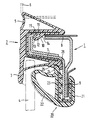
- the only figure shows a cross section through the door frame below the roof area with the attached profiles.
- the vehicle door has a box-shaped frame 1 in the upper region, onto which the U-shaped window guide profile 2 is pushed from the outside, which downwards via a sealing lip 3 against the window pane 4 and upwards via a hollow profile 5 seals against the lower roof edge 6.
- the door frame 1 now consists of two box-shaped sheets 7 and 8 which are brought together at the inner end to form a common flange 9.
- the two sheets 7 and 8 do not now form a closed frame, as was customary hitherto, but leave a gap 10 free on the upper side, in which the horizontally extending sheet end 8 ends at a distance in front of the vertically bent-up region of the sheet 7 and thus one in Leaving gap 10 extending longitudinally of the door.
- the upper leg 11 of the window guide profile 2 has on its inside a web-shaped extension 12 with a front flank 13 running vertically to the leg 11 and an obliquely inclined rear flank 14.
- the extension 12 can also have a hollow chamber 15 so that it can be pushed more easily over the front edge of the sheet 7.
- a sealing profile 20 with its U-shaped clamping region 21 is additionally pushed onto the inner flange 9 of the door frame 1.
- This sealing profile 20 has an extruded hollow profile 22 towards the pane, with which it seals against the closed pane 4.
- the inner leg 23 of this profile also has an extension 24 at its free end, which in a corresponding recess 25 snaps into place at the free end of the lower leg 26 of the window guide profile 2. This catch also supports the underside of the window guide profile 2 and prevents it from evading outwards or being pulled out easily.
Landscapes
- Engineering & Computer Science (AREA)
- Mechanical Engineering (AREA)
- Window Of Vehicle (AREA)
- Seal Device For Vehicle (AREA)
- Body Structure For Vehicles (AREA)
Claims (7)
- Dispositif pour fixer un profilé de guidage de fenêtre (2) sur le cadre (1) d'une portière d'un véhicule automobile, dans lequel le profilé de guidage de fenêtre (2), réalisé en forme de U en coupe transversale, est engagé latéralement, avec des lèvres d'étanchéité (3) qui font saillie latéralement, sur le cadre en forme de bolte (1) de la portière, en direction de la fenêtre et du longeron de toit, caractérisé par le fait que le cadre en forme de boîte (1) de la portière possède, sur son côté supérieur, une fente (10) qui s'étend dans la direction longitudinale, et le profilé de guidage de fenêtre (2) en forme de U possède, sur sa face intérieure, une partie saillante (12) en forme de barrette, la réalisation étant telle qu'après engagement du profilé (2), la partie saillante (12) s'encliquette dans la fente (10) du cadre (1) de la porte.
- Dispositif suivant la revendication 1, caractérisé par le fait que la partie saillante (12) en forme de barrette possède un flanc vertical (13) en direction de la face extérieure de la portière et un flanc incliné obliquement (14) en direction de la face intérieure de la portière.
- Dispositif suivant la revendication 1 ou 2, caractérisé par le fait que la fente (10) est d'une largeur légèrement supérieure à la largeur de base de la partie saillante (12) en forme de barrette.
- Dispositif suivant la revendication 2, caractérisé par le fait que la partie saillante (12) en forme de barrette possède une chambre creuse (15).
- Dispositif suivant l'une des revendications 1 à 4, caractérisé par le fait que le profilé en forme de U (2) possède une armature métallique (16).
- Dispositif suivant la revendication 5, caractérisé par le fait qu'une lèvre d'étanchéité (3), qui s'applique de façon étanche contre la vitre (4), lorsque cette dernière est fermée, s'étend à partir de la base du profilé (2) et qu'un profilé triangulaire de fixation (6) est co-extrudé sur la branche supérieure (11) du profilé, pour s'étendre en direction de la partie de toit (6).
- Dispositif suivant la revendication 1, caractérisé par le fait que, sur le côté intérieur de la vitre, sur la bride en tôle (9), qui est parallèle à la vitre (4), du cadre (1) de la portière est fixé par blocage un profilé d'étanchéité en forme de U (20), qui, avec un profilé creux (22) co-extrudé latéralement, établit l'étanchéité par rapport à la vitre (4) fermée et dont la branche intérieure (23) s'engage, par une partie saillante prolongée (24), dans un évidement latéral (25) ménagé dans la branche inférieure (26) du profilé de guidage de fenêtre (2).
Applications Claiming Priority (2)
| Application Number | Priority Date | Filing Date | Title |
|---|---|---|---|
| DE4017813A DE4017813A1 (de) | 1990-06-01 | 1990-06-01 | Anordnung zur halterung eines fensterfuehrungsprofils |
| DE4017813 | 1990-06-01 |
Publications (2)
| Publication Number | Publication Date |
|---|---|
| EP0459219A1 EP0459219A1 (fr) | 1991-12-04 |
| EP0459219B1 true EP0459219B1 (fr) | 1993-10-27 |
Family
ID=6407702
Family Applications (1)
| Application Number | Title | Priority Date | Filing Date |
|---|---|---|---|
| EP91107852A Expired - Lifetime EP0459219B1 (fr) | 1990-06-01 | 1991-05-15 | Arrangement pour fixer un profil de guidage de fenêtre |
Country Status (5)
| Country | Link |
|---|---|
| US (1) | US5139305A (fr) |
| EP (1) | EP0459219B1 (fr) |
| JP (1) | JP2700963B2 (fr) |
| DE (2) | DE4017813A1 (fr) |
| ES (1) | ES2046820T3 (fr) |
Families Citing this family (20)
| Publication number | Priority date | Publication date | Assignee | Title |
|---|---|---|---|---|
| GB2267527B (en) * | 1992-06-05 | 1996-03-13 | Draftex Ind Ltd | Sealing and guiding arrangements |
| DE4225974C2 (de) * | 1992-08-06 | 1996-10-31 | Man Nutzfahrzeuge Ag | Kurbelfenster in der Fahrerhaustür eines Lkw |
| FR2701903B1 (fr) * | 1993-02-23 | 1995-05-24 | Technistan | Joint d'étanchéité pour vitre coulissante de véhicule automobile et son utilisation comme coulisse. |
| DE4308214C2 (de) * | 1993-03-15 | 1996-12-12 | Metzeler Automotive Profiles | Dichtungsanordnung für einen Deckel an einem Fahrzeugdach |
| JPH08268066A (ja) * | 1995-03-30 | 1996-10-15 | Nishikawa Rubber Co Ltd | フロントドアのシール構造 |
| GB2309994B (en) * | 1996-02-06 | 1999-10-06 | Draftex Ind Ltd | Sealing arrangements |
| DE19715897A1 (de) * | 1997-04-16 | 1998-10-22 | Man Nutzfahrzeuge Ag | Kurbelfenster in einer Fahrzeugtür |
| DE19821694B4 (de) * | 1998-05-14 | 2004-07-22 | Webasto Karosseriesysteme Gmbh | Rahmen für ein Fahrzeug-Schiebedach bzw. -Schiebehebedach |
| DE29808826U1 (de) * | 1998-05-15 | 1999-09-30 | Siemens AG, 80333 München | Schließvorrichtung, insbesondere für eine Kraftfahrzeug-Fensterscheibe |
| DE29901918U1 (de) * | 1999-02-04 | 2000-03-16 | Meteor Gummiwerke K. H. Bädje GmbH & Co, 31167 Bockenem | Rahmendichtungsprofil |
| US6328373B1 (en) * | 2000-09-18 | 2001-12-11 | The Budd Company | Encapsulated vehicle door frame |
| KR100384073B1 (ko) * | 2000-12-14 | 2003-05-14 | 기아자동차주식회사 | 자동차의 윈드실드 글라스 몰딩구조 |
| ITTO20020183A1 (it) * | 2002-03-05 | 2003-09-05 | Metzeler Automotive Profile | Sistema di sigillatura a tenuta per una finestra di un autoveicolo. |
| US20050072053A1 (en) * | 2003-10-06 | 2005-04-07 | Filipczak Larry Andrew | Seal and molding assembly |
| GB2426275A (en) * | 2005-05-20 | 2006-11-22 | Gdx North America Inc | Sealing or guiding assembly for a closure member eg window |
| DE102006028050A1 (de) * | 2006-06-19 | 2007-03-01 | Audi Ag | Dichtungsanordnung für eine Fensterscheibe in einer Fahrzeugkarosserie |
| DE202006010859U1 (de) * | 2006-07-12 | 2006-08-31 | Meteor Gummiwerke K.H. Bädje GmbH & Co. KG | Dichtungsanordnung |
| JP2013184627A (ja) * | 2012-03-09 | 2013-09-19 | Toyoda Gosei Co Ltd | ガラスラン |
| DE102013101896A1 (de) * | 2013-02-26 | 2014-08-28 | Bayerische Motoren Werke Aktiengesellschaft | Dichtungsprofil |
| CN104191947A (zh) * | 2014-09-28 | 2014-12-10 | 无锡市东北塘永丰橡塑厂 | 一种汽车门窗密封条 |
Family Cites Families (10)
| Publication number | Priority date | Publication date | Assignee | Title |
|---|---|---|---|---|
| JPS6064026A (ja) * | 1983-09-17 | 1985-04-12 | Kinugawa Rubber Ind Co Ltd | ドアシ−ル構造 |
| DE3512973C2 (de) * | 1984-05-08 | 1993-12-23 | Volkswagen Ag | Dichtstreifen für eine verschiebbare Fensterscheibe in einer Tür, insbesondere eine absenkbare Fensterscheibe in einer Fahrzeugtür |
| DE3442241A1 (de) * | 1984-11-19 | 1986-05-28 | Metzeler Kautschuk GmbH, 8000 München | Vorrichtung zur gleichzeitigen abdichtung der tuerscheibe und des dachbereiches einer kraftfahrzeug-tuer |
| FR2580999B1 (fr) * | 1985-04-26 | 1987-06-05 | Renault | Dispositif de guidage d'une vitre descendante de porte de vehicule automobile |
| JPS62201115U (fr) * | 1986-04-07 | 1987-12-22 | ||
| US4951418A (en) * | 1988-04-06 | 1990-08-28 | The Standard Products Company | Glass run molding |
| US4937126A (en) * | 1988-05-03 | 1990-06-26 | The Standard Products Company | Smooth flexible flange cover |
| FR2633661A1 (fr) * | 1988-06-30 | 1990-01-05 | Smadja Jean Claude | Dispositif formant joint d'etancheite pour vitres affleurantes |
| GB2223258B (en) * | 1988-09-30 | 1992-04-22 | Draftex Ind Ltd | Sealing and retaining strips |
| GB2233377B (en) * | 1989-06-21 | 1993-08-25 | Draftex Ind Ltd | Sealing strips |
-
1990
- 1990-06-01 DE DE4017813A patent/DE4017813A1/de not_active Withdrawn
-
1991
- 1991-05-15 EP EP91107852A patent/EP0459219B1/fr not_active Expired - Lifetime
- 1991-05-15 JP JP3140846A patent/JP2700963B2/ja not_active Expired - Lifetime
- 1991-05-15 DE DE91107852T patent/DE59100524D1/de not_active Expired - Fee Related
- 1991-05-15 ES ES199191107852T patent/ES2046820T3/es not_active Expired - Lifetime
- 1991-06-03 US US07/709,647 patent/US5139305A/en not_active Expired - Fee Related
Also Published As
| Publication number | Publication date |
|---|---|
| EP0459219A1 (fr) | 1991-12-04 |
| JP2700963B2 (ja) | 1998-01-21 |
| DE59100524D1 (de) | 1993-12-02 |
| ES2046820T3 (es) | 1994-02-01 |
| JPH04231210A (ja) | 1992-08-20 |
| US5139305A (en) | 1992-08-18 |
| DE4017813A1 (de) | 1991-12-05 |
Similar Documents
| Publication | Publication Date | Title |
|---|---|---|
| EP0459219B1 (fr) | Arrangement pour fixer un profil de guidage de fenêtre | |
| DE10115124C2 (de) | Sicherungseinrichtung für eine Türscheibe eines Kraftfahrzeugs | |
| DE3822378C2 (de) | Fensterrollo für ein Kraftfahrzeug | |
| EP0654372B1 (fr) | Système d'étanchéité entre les fenêtres de véhicules et une capote pliable | |
| DE568435T1 (de) | Dichtung, insbesondere zur Bildung einer Gleitführungsschiene für ein bewegliches Kraftfahrzeugsfenster. | |
| DE19639280A1 (de) | Kraftfahrzeugtür | |
| WO2021043788A1 (fr) | Guide de vitre pour une vitre d'un véhicule automobile | |
| EP3508680A1 (fr) | Dispositif d'étanchéité et porte sectionnelle équipée d'un tel dispositif d'étanchéité | |
| DE3836687C2 (de) | Dachzierleiste für ein Kraftfahrzeug | |
| DE8709264U1 (de) | Kunststoffrahmen für Fenster, Türen od.dgl. | |
| DE3312470C2 (fr) | ||
| DE4203364C2 (de) | Dichtleiste für Seitenfenster von Kraftfahrzeugen ohne B-Säule | |
| EP0872369B1 (fr) | Fenêtre coulissante pour porte de véhicule | |
| DE3538562A1 (de) | Fensterrahmen, insbesondere fuer eine kraftfahrzeugtuer | |
| DE2522112A1 (de) | Fensterzarge | |
| DE4017196C1 (en) | Sealing strip for car rear window - comprises H=section strip, one side of which forms water-removing gutter | |
| DE3340476A1 (de) | Fahrzeugfenster mit einer verschiebbaren fensterscheibe | |
| DE29807479U1 (de) | Türmodul für eine Fahrzeugtür | |
| DE3235026A1 (de) | Scheibenfuehrung fuer hoehenverschiebbare fensterscheiben in einem fahrzeug | |
| DE2203280A1 (de) | Verbundfenster oder -tuer | |
| DE29912962U1 (de) | Tür mit Bodendichtung | |
| DE3400815C1 (de) | Verriegelungsbeschlag an Fenstern, Türen und dergleichen | |
| DE102005053572B4 (de) | Führungsvorrichtung für Scheiben von Kraftfahrzeugtüren | |
| DE19714642A1 (de) | Türscheibendichtung zur Befestigung in einer Türausnehmung | |
| DE2601795C2 (de) | Dichtung am Mittelstoss von Fenstern oder Türen mit horizontal verschiebbaren Flügeln |
Legal Events
| Date | Code | Title | Description |
|---|---|---|---|
| PUAI | Public reference made under article 153(3) epc to a published international application that has entered the european phase |
Free format text: ORIGINAL CODE: 0009012 |
|
| AK | Designated contracting states |
Kind code of ref document: A1 Designated state(s): DE ES FR GB IT |
|
| 17P | Request for examination filed |
Effective date: 19920115 |
|
| 17Q | First examination report despatched |
Effective date: 19930405 |
|
| GRAA | (expected) grant |
Free format text: ORIGINAL CODE: 0009210 |
|
| AK | Designated contracting states |
Kind code of ref document: B1 Designated state(s): DE ES FR GB IT |
|
| REF | Corresponds to: |
Ref document number: 59100524 Country of ref document: DE Date of ref document: 19931202 |
|
| GBT | Gb: translation of ep patent filed (gb section 77(6)(a)/1977) |
Effective date: 19931108 |
|
| ITF | It: translation for a ep patent filed | ||
| REG | Reference to a national code |
Ref country code: ES Ref legal event code: FG2A Ref document number: 2046820 Country of ref document: ES Kind code of ref document: T3 |
|
| ET | Fr: translation filed | ||
| PLBE | No opposition filed within time limit |
Free format text: ORIGINAL CODE: 0009261 |
|
| STAA | Information on the status of an ep patent application or granted ep patent |
Free format text: STATUS: NO OPPOSITION FILED WITHIN TIME LIMIT |
|
| 26N | No opposition filed | ||
| PGFP | Annual fee paid to national office [announced via postgrant information from national office to epo] |
Ref country code: FR Payment date: 19980417 Year of fee payment: 8 |
|
| PGFP | Annual fee paid to national office [announced via postgrant information from national office to epo] |
Ref country code: GB Payment date: 19980422 Year of fee payment: 8 |
|
| PGFP | Annual fee paid to national office [announced via postgrant information from national office to epo] |
Ref country code: ES Payment date: 19980526 Year of fee payment: 8 |
|
| PGFP | Annual fee paid to national office [announced via postgrant information from national office to epo] |
Ref country code: DE Payment date: 19980528 Year of fee payment: 8 |
|
| PG25 | Lapsed in a contracting state [announced via postgrant information from national office to epo] |
Ref country code: GB Free format text: LAPSE BECAUSE OF NON-PAYMENT OF DUE FEES Effective date: 19990515 |
|
| PG25 | Lapsed in a contracting state [announced via postgrant information from national office to epo] |
Ref country code: ES Free format text: LAPSE BECAUSE OF NON-PAYMENT OF DUE FEES Effective date: 19990517 |
|
| GBPC | Gb: european patent ceased through non-payment of renewal fee |
Effective date: 19990515 |
|
| PG25 | Lapsed in a contracting state [announced via postgrant information from national office to epo] |
Ref country code: FR Free format text: LAPSE BECAUSE OF NON-PAYMENT OF DUE FEES Effective date: 20000131 |
|
| PG25 | Lapsed in a contracting state [announced via postgrant information from national office to epo] |
Ref country code: DE Free format text: LAPSE BECAUSE OF NON-PAYMENT OF DUE FEES Effective date: 20000301 |
|
| REG | Reference to a national code |
Ref country code: FR Ref legal event code: ST |
|
| REG | Reference to a national code |
Ref country code: ES Ref legal event code: FD2A Effective date: 20010503 |
|
| PG25 | Lapsed in a contracting state [announced via postgrant information from national office to epo] |
Ref country code: IT Free format text: LAPSE BECAUSE OF NON-PAYMENT OF DUE FEES;WARNING: LAPSES OF ITALIAN PATENTS WITH EFFECTIVE DATE BEFORE 2007 MAY HAVE OCCURRED AT ANY TIME BEFORE 2007. THE CORRECT EFFECTIVE DATE MAY BE DIFFERENT FROM THE ONE RECORDED. Effective date: 20050515 |