EP0459475A1 - Vorrichtung zur dosierten Austragung von Schüttgut aus einem Behälter - Google Patents
Vorrichtung zur dosierten Austragung von Schüttgut aus einem Behälter Download PDFInfo
- Publication number
- EP0459475A1 EP0459475A1 EP91108844A EP91108844A EP0459475A1 EP 0459475 A1 EP0459475 A1 EP 0459475A1 EP 91108844 A EP91108844 A EP 91108844A EP 91108844 A EP91108844 A EP 91108844A EP 0459475 A1 EP0459475 A1 EP 0459475A1
- Authority
- EP
- European Patent Office
- Prior art keywords
- funnel
- film
- hollow cylindrical
- opening
- shaped film
- Prior art date
- Legal status (The legal status is an assumption and is not a legal conclusion. Google has not performed a legal analysis and makes no representation as to the accuracy of the status listed.)
- Granted
Links
- 239000008187 granular material Substances 0.000 title abstract 4
- 239000013590 bulk material Substances 0.000 claims description 13
- 239000000463 material Substances 0.000 claims description 4
- 239000000203 mixture Substances 0.000 claims description 4
- 230000004913 activation Effects 0.000 claims description 3
- 239000002131 composite material Substances 0.000 claims description 2
- 239000004744 fabric Substances 0.000 claims description 2
- 239000005445 natural material Substances 0.000 claims description 2
- 230000003213 activating effect Effects 0.000 claims 1
- 238000004519 manufacturing process Methods 0.000 claims 1
- 230000006378 damage Effects 0.000 abstract description 6
- 230000003628 erosive effect Effects 0.000 abstract description 5
- 239000000126 substance Substances 0.000 abstract description 4
- 238000011109 contamination Methods 0.000 abstract description 2
- 230000001105 regulatory effect Effects 0.000 abstract description 2
- 239000003344 environmental pollutant Substances 0.000 abstract 1
- 239000010705 motor oil Substances 0.000 abstract 1
- 231100000719 pollutant Toxicity 0.000 abstract 1
- 238000005516 engineering process Methods 0.000 description 2
- 238000004026 adhesive bonding Methods 0.000 description 1
- 239000003242 anti bacterial agent Substances 0.000 description 1
- 229940088710 antibiotic agent Drugs 0.000 description 1
- 230000015572 biosynthetic process Effects 0.000 description 1
- 230000001419 dependent effect Effects 0.000 description 1
- 238000007599 discharging Methods 0.000 description 1
- 239000003814 drug Substances 0.000 description 1
- 239000000835 fiber Substances 0.000 description 1
- 239000012208 gear oil Substances 0.000 description 1
- 229910052751 metal Inorganic materials 0.000 description 1
- 239000002184 metal Substances 0.000 description 1
- 229910001510 metal chloride Inorganic materials 0.000 description 1
- 229910044991 metal oxide Inorganic materials 0.000 description 1
- 150000004706 metal oxides Chemical class 0.000 description 1
- 150000002739 metals Chemical class 0.000 description 1
- 210000002381 plasma Anatomy 0.000 description 1
- 239000002994 raw material Substances 0.000 description 1
- 238000005245 sintering Methods 0.000 description 1
Images


Classifications
-
- B—PERFORMING OPERATIONS; TRANSPORTING
- B65—CONVEYING; PACKING; STORING; HANDLING THIN OR FILAMENTARY MATERIAL
- B65D—CONTAINERS FOR STORAGE OR TRANSPORT OF ARTICLES OR MATERIALS, e.g. BAGS, BARRELS, BOTTLES, BOXES, CANS, CARTONS, CRATES, DRUMS, JARS, TANKS, HOPPERS, FORWARDING CONTAINERS; ACCESSORIES, CLOSURES, OR FITTINGS THEREFOR; PACKAGING ELEMENTS; PACKAGES
- B65D88/00—Large containers
- B65D88/54—Large containers characterised by means facilitating filling or emptying
- B65D88/64—Large containers characterised by means facilitating filling or emptying preventing bridge formation
- B65D88/68—Large containers characterised by means facilitating filling or emptying preventing bridge formation using rotating devices
Definitions
- the invention relates to a device for the metered discharge of bulk material from a container according to the preamble of claim 1.
- the scraper running between the funnel wall and the film causes the latter to move, which in turn causes a spiral vortex in the bulk material to be discharged.
- the scraper does not come into contact with the product itself.
- the loosening of the product is brought about in a gentle way by the film applied by the stripper. As a result, erosion, damage and destruction of the bulk material grains are avoided. Gluing of the latter and thus the formation of bulk material bridges inside the funnel can no longer occur.
- the funnel-shaped film ensures an undisturbed material flow because there are no mechanical parts inside.
- the film also prevents contamination from various contaminating substances, such as gear oil, etc.
- the film is a cheap wear item and can be replaced without specialist knowledge.
- the chemical nature of the plastic from which the film is made depends on the intended use.
- the discharge device according to the invention can also for handling bulk goods of the highest standard, such as pharmaceuticals (antibiotics, blood plasma, etc.) or raw materials of high-purity technology such as heavy and rare metals for sintering technology, metal oxides for piezoelectric, fiber optics, metal chlorides for the nuclear industry, etc.
- pharmaceuticals antibiotics, blood plasma, etc.
- raw materials of high-purity technology such as heavy and rare metals for sintering technology, metal oxides for piezoelectric, fiber optics, metal chlorides for the nuclear industry, etc.
- the invention also relates to the use of the above-described devices for the simultaneous discharge of bulk material from several silos of a mixer tap in order to produce a product mixture from granular components.
- the tapered lower section of the funnel-shaped film of each discharge device which adjoins the associated hollow cylindrical outlet, is not covered by the fixed outer funnel. It forms an oblique cone with a central axis pointing in the direction of a mixing device, so that the central axes of all oblique cones intersect in the entrance of the mixing device.
- each wiper section having the shape of an inclined cone can be associated with a wiper running on a circular path, which acts on the film only along part of its circular path.
- the device according to the invention for discharging bulk material from a container for example a silo S, comprises a hopper 1 provided after an opening in the silo bottom, at least one scraper 2 arranged in the inner surface of the hopper and a slide 3 for opening, regulating and closing the mouth of a hollow cylindrical outlet 4 adjoining the tapered lower funnel end.
- the scraper 2 is fastened in a manner known per se to an annular body 5 forming the wall of the hollow cylindrical outlet 4, which is rotatably mounted in a gear box 6 and anchored to the same Electric motor 7 is driven.
- a film 8 is also arranged in a funnel-shaped manner, at the beginning at the edge of the opening of the silo bottom between it and the flange 9 of the large-diameter funnel entrance fastened to it and at the exit between the edge of the mouth of the hollow cylindrical outlet 4 and the flange 10 of a pipe 11 provided for the removal of material is clamped.
- the film 8 is expediently made of plastic and composed of several layers of the same. Depending on the intended use, the film 8 can be made of a composite material made of natural material and plastic and also have a gas-permeable quality.
- the funnel-like film 8 can initially only be provided to extend a short distance into the hollow cylindrical outlet 4.
- the funnel-shaped film 8 can alternatively be formed in a scale-like manner from fabric and / or plastic strips 12 which overlap along their edges running in the direction of the generatrix of the funnel jacket surface, the overlap being oriented in the direction of rotation A of the stripper 2 (see arrow A ) and the overlapping edges are each reinforced with a stiffening rod 13 (see. Fig. 3a and b).
- a still further embodiment of the invention provides between the inner surface of the fixed outer funnel 1 and the funnel-shaped film 8 instead of rotating wipers 2, a number of activation bodies 14 which can be acted upon by a pressure medium in a symmetrical distribution.
- the latter can be provided particularly expediently in the form of hoses which can be actuated in a rotating sequence by means of compressed air pulses (cf. FIGS. 4 a and b).
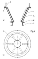
- FIG. 5 illustrates a possible use of devices according to the invention for the simultaneous discharge of bulk material from three silos S of a so-called mixer tap B to create a product mixture from granular components.
- the mixer tap B could of course also be composed of a different number of silos.
- the lower section of the funnel-shaped film 8 of each discharge device which tapers to the associated hollow cylindrical outlet 4 and is not covered by the fixed outer funnel 1.
- said film sections each form an oblique cone with a central axis pointing in the direction of a mixing device 15, so that the central axes of all the oblique cones intersect at the entrance to the mixing device 15.
- a scraper 2 can then be assigned to each such section of film in the form of an oblique cone, which rotates on a circular path and only acts on the film 8 along part of the same.
Landscapes
- Engineering & Computer Science (AREA)
- Mechanical Engineering (AREA)
- Control And Other Processes For Unpacking Of Materials (AREA)
- Filling Or Emptying Of Bunkers, Hoppers, And Tanks (AREA)
- Weight Measurement For Supplying Or Discharging Of Specified Amounts Of Material (AREA)
- Processing And Handling Of Plastics And Other Materials For Molding In General (AREA)
Abstract
Description
- Die Erfindung bezieht sich auf eine Vorrichtung zur dosierten Austragung von Schüttgut aus einem Behälter gemäss dem Oberbegriff des Patentanspruches 1.
- Bekannte gattungsgemässe Austragsapparate streben jeweils nach Gewährleistung eines sicheren, gleichmässigen Austritts des Schüttgutes, indem der mit seiner Vorderkante die Innenfläche des Zuführtrichters entlang geführter Abstreifer im Bereich seines äusseren Endes seiner Drehrichtung entgegensetzt nach rückwärts gebogen ausgeführt und im hohlzylinderischen Auslauf eine in Fallrichtung des Schüttgutes wirkende Förderschnecke, im Falle sich verjüngenden Auslaufs sogar in Kombination mit einem zusätzlichen, ebenfalls entgegengesetzt zu seiner Drehrichtung verbogenen Abstreifer, angeordnet sind.Dabei steht der umlaufende Abstreifer ununterbrochen in Berührung mit dem auszutragenden Schüttgut, so dass dessen Körner einer Erosion, Beschädigung oder gar der Zerstörung ausgesetzt werden. Dieser Sachverhalt steht vielfach einer Verwendung bekannter Austragseinrichtungen zur Handhabung empfindlichen Schüttgutes hinderlich entgegen.
- Hier setzt die Erfindung ein und will eine Vorrichtung beschriebener Art schaffen, die auch die Handhabung besonders erosionsgefährdeter, heikler Substanzen körniger Beschaffenheit ohne schädliche Einwirkung auf dieselben ermöglicht.
- Die geschilderte Aufgabe wird mit Hilfe der Ausbildungsmassnahme gemäss dem Kennzeichen des Patentanspruches 1 gelöst.
- Der zwischen Trichterwand und Folie umlaufende Abstreifer bewirkt eine Bewegung der letzteren, die ihrerseits im auszutragenden Schüttgut einen Spiralwirbel hervorruft. Dabei kommt der Abstreifer nicht mit dem Gut selbst in Berührung. Die Auflockerung des Produktes wird durch die vom Abstreifer beaufschlagte Folie auf schonende Weise herbeigeführt. Demzufolge wird Erosion,.Beschädigung und Zerstörung der Schüttgutkörner vermieden. Ein Verkleben der letzteren und somit die Ausbildung von Schüttgutbrücken im Innern des Trichters kann nicht mehr auftreten. Die trichterförmige Folie stellt einen ungestörten Materialdurchlauf sicher, da im Innern derselben mechanische Teile fehlen.
- Auch eine Kontamination durch verschiedene verunreinigende Substanzen, wie beispielsweise Getriebeöl usw., wird durch die Folie verhindert.
- Die Folie ist ein billiger Verschleissartikel und lässt sich ohne fachmännische Kenntnisse ersetzen. Die chemische Beschaffenheit des Kunststoffes, aus dem die Folie gefertigt wird, richtet sich je nach dem Verwendungszweck.
- Da durch Verwendung der Folie die Materialerosion minimiert ist, kann die Austragsvorrichtung gemäss der Erfindung auch für die Handhabung von Schüttgut höchster Anspruchsklasse, wie beispielsweise Pharmazeutika (Antibiotika, Blutplasma usw.) oder Rohstoffe der Hochreintechnik wie Schwer- und seltene Metalle für die Sintertechnik, Metalloxyde für Piezoelektrik, Fiberoptics, Metallchloride für die Nuklearindustrie usw. eingesetzt werden.
- Merkmale einer besonders vorteilhaften Weiterausbildung der Erfindung gehen aus den abhängigen Patentansprüchen 2 bis 12 hervor.
- Die Erfindung betrifft ferner auch die Verwendung hierzuvor beschriebener Vorrichtungen zur gleichzeitigen Austragung von Schüttgut aus mehreren Silos einer Mischbatterie zur Erstellung eines Produktgemisches aus körnigen Komponenten. Dabei ist der sich verjüngend jeweils an den zugehörigen hohlzylinderischen Auslauf anschliessende, untere Abschnitt der trichterförmigen Folie einer jeden Austragsvorrichtung nicht durch den festen äusseren Trichter überdeckt. Er bildet einen schiefen Kegel mit in Richtung einer Mischvorrichtung weisender Mittelachse, so dass sich die Mittelachsen sämtlicher schiefer Kegel im Eingang der Mischvorrichtung schneiden. Es kann ferner jedem die Gestalt eines schiefen Kegels aufweisenden Folienabschnitt ein auf einer Kreisbahn umlaufender Abstreifer zugeordnet sein, der lediglich längs einem Teil seiner Kreisbahn auf die Folie einwirkt.
- Die Erfindung wird beispielsweise anhand einiger bevorzugter Ausführungsformen gemäss der Zeichnung näher erläutert.
- Es zeigen:
- Figur 1
- Aufriss einer Vorrichtung gemäss der Erfindung zur dosierten Austragung von Schüttgut aus einem Behälter im Schnitt,
- Figur 2
- Aufriss einer anderen Ausführungsform des Erfindungsgegenstandes ebenfalls im Schnitt,
- Figur 3a
- vollständige Draufsicht auf eine andere Ausführungsart einer wichtigen Einzelheit der erfindungsgemässen Austragsvorrichtung
- Figur 3b
- vergrösserte teilweise Draufsicht auf die Einzelheit gemäss der Figur 3a auf der Höhe des grossquerschnittigen Einganges der Austragtragsvorrichtung,
- Figur 4a
- Aufriss einer noch weiteren Ausführungsform des Erfindungsgegenstandes im Schnitt,
- Figur 4b
- Draufsicht auf die Ausführungsform nach der Figur 4a und
- Figur 5
- Darstellung einer sogenannten Mischbatterie, bestehend aus drei Silos je mit einer Austragsvorrichtung gemäss der Erfindung und einer Mischvorrichtung, zur Erstellung von Produktgemischen.
- Die erfindungsgemässe Vorrichtung zur Austragung von Schüttgut aus einem Behälter, beispielsweise einem Silo S, umfasst einen im Anschluss an eine Oeffnung im Siloboden vorgesehenen Trichter 1, mindestens einen in diesem dessen Innenfläche entlang umlaufend angeordneten Abstreifer 2 und einen Schieber 3 zum Oeffnen, Regulieren und Verschliessen der Mündung eines an das verjüngte untere Trichterende anschliessenden, hohlzylinderischen Auslaufs 4. Der Abstreifer 2 ist in an sich bekannter Weise an einem die Wandung des hohlzylinderischen Auslaufes 4 bildenden Ringkörpers 5 befestigt, der in einem Getriebekasten 6 drehbar gelagert ist und von einem an demselben verankerten Elektromotor 7 angetrieben wird.
- Innerhalb einer vom Abstreifer 2 zu bestreichenden, imaginären Kegelfläche ist eine Folie 8 ebenfalls trichterförmig angeordnet, indem sie eingangs am Rande der Oeffnung des Silobodens zwischen diesem und dem am selben befestigten Flansch 9 des grossdurchschnittigen Trichtereinganges und ausgangs zwischen dem Rand der Mündung des hohlzylinderischen Auslaufes 4 und dem Flansch 10 eines für die Gutentnahme vorgesehenen Rohres 11 eingeklemmt ist.
- Die Folie 8 wird zweckmässig aus Kunststoff hergestellt und aus mehreren Lagen derselben zusammengesetzt. Je nach Verwendungszweck kann die Folie 8 aus einem Verbundwerkstoff aus natürlichen Stoff und Kusntstoff gefertigt sein und auch eine gasdurchlässige Beschaffenheit aufweisen.
- Bei einer anderen Ausführungsform der erfindungsgemässen Vorrichtung kann die trichterartige Folie 8 ausgangs lediglich ein kurzes Stück in den hohlzylinderischen Auslauf 4 hinein erstreckend vorgesehen sein.
- Nach einer weiteren anderen Ausführungsart der Erfindung ist es möglich, auf den festen Trichter 1 überhaupt zu verzichten (vgl. Fig.2). Es empfiehlt sich in diesem Fall, zwischen der Peripherie der Oeffnung des Behälterbodens und dem den hohlzylinderischen Auslauf 4 enthaltenden Getriebekasten 6 ausserhalb der vom Abstreifer 2 zu bestreichenden, imaginären Kegelfläche eine Anzahl von Streben (nicht dargestellt in der Zeichnung) anzuordnen.
- Die trichterförmige Folie 8 kann alternativ schuppenartig aus Stoff- und/oder Kunststoffstreifen 12 ausgebildet sein, die sich entlang ihrer in Richtung von Erzeugendem der Trichtermantelfläche verlaufenden Kanten überlappen, wobei die Ueberlappung jeweils in die Drehrichtung A des Abstreifers 2 orientiert ist (vgl. Pfeil A) und die überlappenden Kanten je mit einer Versteifungsstange 13 verstärkt sind (vgl. Fig. 3a und b).
- Eine noch weitere Ausführungsform der Erfindung sieht zwischen der Innenfläche des festen äusseren Trichters 1 und der trichterförmigen Folie 8 anstelle umlaufender Abstreifer 2 eine Anzahl mit Hilfe eines Druckmittels beaufschlagbarer Aktivierungskörper 14 in symmetrischer Verteilung vor. Die letzteren können besonders zweckmässig in Form von Schläuchen vorgesehen sein, die mittels Druckluftimpulse in umlaufender Reihenfolge betätigbar sind (vgl. Fig.4a und b). Es liesse sich jedoch auch ein schneckenartig um die trichterförmige Folie 8 gewundener, druckbeaufschlagbarer Schlauch als Aktivierungskörper 14 verwenden.
- Die Figur 5 veranschaulicht eine mögliche Verwendung von erfindungsgemässen Vorrichtungen zur gleichzeitigen Austragung von Schüttgut aus drei Silos S einer sogenannten Mischbatterie B zur Erstellung eines Produktgemisches aus körnigen Komponenten.Die Mischbatterie B könnte natürlich auch einer anderen Anzahl Silos zusammengesetzt sein. Es ist hierbei der sich verjüngend jeweils an den zugehörigen, hohlzylinderischen Auslauf 4 anschliessende, untere Abschnitt der trichterförmigen Folie 8 einer jeder Austragsvorrichtung nicht durch den festen äusseren Trichter 1 überdeckt. Die besagten Folieabschnitte bilden vielmehr je einen schiefen Kegel mit in Richtung einer Mischvorrichtung 15 weisender Mittelachse, so dass sich die Mittelachsen sämtlicher schiefer Kegel im Eingang der Mischvorrichtung 15 schneiden. Einem jedem solchem Folienabschnitt von der Gestalt eines schiefen Kegels kann dann ein Abstreifer 2 zugeordnet sein, der auf einem Kreisbahn umläuft und dabei lediglich entlang einem Teil desselben auf die Folie 8 einwirkt.
Claims (14)
- Vorrichtung zur dosierten Austragung von Schüttgut aus einem Behälter, mit einem im Anschluss an eine Oeffnung im Behälterboden vorgesehenen Trichter, mindestens einem im diesem dessen Innenfläche entlang umlaufend angeordneten Abstreifer und einem Schieber zum Oeffnen und Verschliessen der Mündung eines an das verjüngte untere Trichterende anschliessendem, hohlzylinderischen Auslaufs, gekennzeichnet durch eine zwischen der Oeffnung im Bodenhälterboden und dem hohlzylinderischen Auslauf (4) innerhalb eines vom Abstreifer (2) zu bestreichenden, imaginären Kegelfläche ebenfalls trichterförmig angeordnete Folie (8).
- Vorrichtung nach Patentanspruch 1, dadurch gekennzeichnet, dass die Folie (8) aus Kunststoff besteht und aus mehreren Lagen desselben zusammengesetzt ist.
- Vorrichtung nach Patentanspruch 1, dadurch gekennzeichnet, dass die Folie (8) aus einem aus natürlichem Stoff und Kunststoff bestehenden Verbundwerkstoff gefertigt ist.
- Vorrichtung nach Patentanspruch 2 oder 3, dadurch gekennzeichnet, dass die Folie (8) gasdurchlässige Beschaffenheit aufweist.
- Vorrichtung nach einem der Patentansprüche 2 oder 3 oder 4, dadurch gekennzeichnet, dass die trichterförmige Folie (8) mit ihrem Eingang am Rand der Oeffnung im Behälterboden zwischen diesem und dem am selben befestigten Flansch (9) des grossquerschnittigen Einganges des festen äusseren Trichters (1) und mit ihrem Ausgang zwischen dem Rand der Mündung des hohlzylinderischen Auslaufs (4) und dem Flansch (10) eines Rohres (11) für die Gutsentnahme eingeklemmt ist.
- Vorrichtung nach einem der Patentansprüche 2 oder 3 oder 4, dadurch gekennzeichnet, dass sich die trichterförmige Folie (8) mit ihrem unbefestigten Ausgang lediglich ein kurzes Stück in den hohlzylinderischen Auslauf (4) hinein erstreckt.
- Vorrichtung nach Patentanspruch 5, dadurch gekennzeichnet, dass kein fester äusserer Trichter (1) vorgesehen ist.
- Vorrichtung nach Patentanspruch 7, gekennzeichnet durch eine Anzahl zwischen der Peripherie der Oeffnung im Behälterboden und einem den hohlzylinderischen Auslauf (4) enthaltenden Getriebekasten (6) ausserhalb der vom Abstreifer (2) zu bestreichenden, imaginären Kegelfläche angeordneter Streben.
- Vorrichtung nach Patentsprüchen 2 und 5 oder 3 und 5, gekennzeichnet, durch eine trichterförmige Folie (8), die schuppenartig aus Stoff- und/oder Kunststoffstreifen (12) gebildet ist, welche letztere sich entlang ihrer in Richtung vom Erzeugenden der Trichtermantelfläche verlaufenden Kanten überlappen, wobei die Ueberlappung jeweils in die Drehrichtung (A) des Abstreifers (2) orientiert ist und die überlappenden Kanten je mit einer Versteifungsstange (13) verstärkt sind.
- Vorrichtung nach Patentanspruch 5 oder 6 dadurch gekennzeichnet, dass zwischen der Innenfläche des festen äusseren Trichters (1) und der trichterförmige Folie (8) anstelle umlaufender Abstreifer (2) eine Anzahl mit Hilfe eines Druckmittels beaufschlagbarer Aktivierungskörper (14) in symmetrischer Verteilung angeordnet ist.
- Vorrichtung nach Patentanspruch 10, dadurch gekennzeichnet, dass die Aktivierungskörper (14) mittels Druckluftimpulse in umlaufender Reihenfolge betätigbare Schläuche sind.
- Vorrichtung nach Patentanspruch 10, dadurch gekennzeichnet, dass ein druckbeaufschlagbarer Schlauch schneckenartig um die trichterförmige Folie (8) gewunden ist.
- Verwendung von Vorrichtungen nach den Patentansprüchen 1 bis 5 zur gleichzeitigen Austragung von Schüttgut aus mehreren Silos (S) einer Mischbatterie (B) zur Erstellung eines Produktgemisches aus körnigen Komponenten, wobei der sich verjüngend jeweils an den zugehörigen hohlzylinderischen Auslauf (4) anschliessende, untere Abschnitt der trichterförmigen Folie (8) einer jeder Austragsvorrichtung nicht durch den festen äusseren Trichter (1) überdeckt ist und einen schiefen Kegel mit in Richtung einer Mischvorrichtung (15) weisender Mittelachse bildet, so dass sich die Mittelachsen sämtlicher schiefer Kegel im Eingang der Mischvorrichtung (15) schneiden.
- Verwendung nach Patentanspruch 13, wobei jedem die Gestalt eines schiefen Kegels aufweisenden Abschnitt der trichterförmigen Folien (8) ein auf einer Kreisbahn umlaufender Abstreifer (2) zugeordnet ist, der lediglich entlang einem Teil seiner Kreisbahn auf die Folie (8) einwirkt.
Applications Claiming Priority (2)
| Application Number | Priority Date | Filing Date | Title |
|---|---|---|---|
| CH187390 | 1990-06-01 | ||
| CH1873/90 | 1990-06-01 |
Publications (2)
| Publication Number | Publication Date |
|---|---|
| EP0459475A1 true EP0459475A1 (de) | 1991-12-04 |
| EP0459475B1 EP0459475B1 (de) | 1997-07-30 |
Family
ID=4220593
Family Applications (1)
| Application Number | Title | Priority Date | Filing Date |
|---|---|---|---|
| EP91108844A Expired - Lifetime EP0459475B1 (de) | 1990-06-01 | 1991-05-29 | Vorrichtung zur dosierten Austragung von Schüttgut aus einem Behälter |
Country Status (6)
| Country | Link |
|---|---|
| US (1) | US5353966A (de) |
| EP (1) | EP0459475B1 (de) |
| JP (1) | JP3100672B2 (de) |
| AT (1) | ATE156089T1 (de) |
| DE (1) | DE59108803D1 (de) |
| DK (1) | DK0459475T3 (de) |
Cited By (2)
| Publication number | Priority date | Publication date | Assignee | Title |
|---|---|---|---|---|
| EP0854099A1 (de) * | 1997-01-17 | 1998-07-22 | ANAG A. Nussbaumer AG | Vorrichtung zum Austragen von Schüttgut aus einem Behälter und Verschlussorgan dafür |
| US8746294B2 (en) | 2008-07-22 | 2014-06-10 | Amann Girrbach Ag | Metering device for powdery substances |
Families Citing this family (7)
| Publication number | Priority date | Publication date | Assignee | Title |
|---|---|---|---|---|
| ITTO20020764A1 (it) * | 2002-09-03 | 2004-03-04 | Paolo Debolini | Dispositivo per la rimozione di materiale dalle pareti |
| US20040245144A1 (en) * | 2003-06-03 | 2004-12-09 | Hurst William E. | Preformed mixing bag for dry powder, apparatus, method and system for using same |
| US20040245124A1 (en) * | 2003-06-03 | 2004-12-09 | Hurst William E. | Preformed mixing bag for dry powder, apparatus, method and system for using same |
| EP2351490B1 (de) * | 2010-01-27 | 2018-10-17 | Kraft Foods R & D, Inc. | Vorrichtung und Verfahren zur durchgehenden Zufuhr von Schokoladenzutaten und System und Verfahren zur Herstellung von Schokoladenmasse |
| CN107745891A (zh) * | 2017-10-31 | 2018-03-02 | 濮阳市鸿宇压力容器有限公司 | 一种新型旋转清堵机 |
| US11155424B2 (en) * | 2019-11-07 | 2021-10-26 | Cnh Industrial America Llc | Pneumatically inflated pillow for grain bin unload |
| EP4108602A1 (de) * | 2021-06-21 | 2022-12-28 | Macgregor Sweden AB | Aufbewahrungs- und wiedergewinnungssystem für schüttgut |
Citations (6)
| Publication number | Priority date | Publication date | Assignee | Title |
|---|---|---|---|---|
| DE1119169B (de) * | 1959-05-23 | 1961-12-07 | Noblee & Thoerl G M B H | Ortsfester Bunker fuer Schuettgueter |
| FR1591437A (de) * | 1968-11-13 | 1970-04-27 | ||
| DE1815008A1 (de) * | 1968-12-17 | 1970-06-25 | Spitzer Kg Ludwig Sen | Quaderfoermiger,langgestreckter,stapelbarer Grossraumcontainer |
| CH529679A (de) * | 1971-11-16 | 1972-10-31 | Kokeisl Theodor | Einrichtung an Behältern zur Aufnahme und zur dosierten Entnahme von Schüttgut |
| FR2132984A5 (en) * | 1971-04-02 | 1972-11-24 | Kleber Colombes | Flexible pipe - for powdered pdts with fabric walls having inner lining of smooth elastomer material |
| US4342383A (en) * | 1980-04-17 | 1982-08-03 | Burnett William C | Method and apparatus for controlling the fall of grain through a conduit |
Family Cites Families (16)
| Publication number | Priority date | Publication date | Assignee | Title |
|---|---|---|---|---|
| US1987289A (en) * | 1931-05-02 | 1935-01-08 | Dan D Gardner | Method and means for fueling and controlling furnaces |
| US2381802A (en) * | 1941-10-23 | 1945-08-07 | Wallace & Tiernan Co Inc | Dry chemical feeder |
| US2560480A (en) * | 1947-05-13 | 1951-07-10 | John B Rogers | Hopper shaker plate and comb assembly |
| US2646905A (en) * | 1950-11-01 | 1953-07-28 | Goodrich Co B F | Inflatable panel assembly for storage bins |
| US2756906A (en) * | 1952-04-01 | 1956-07-31 | Clarence F Carter | Filling machine |
| US3099494A (en) * | 1961-06-06 | 1963-07-30 | Fmc Corp | Feed device with fluid activated rippling sheets |
| DE1196329B (de) * | 1962-08-31 | 1965-07-08 | Ullrich & Roser G M B H | Pneumatischer Formsandfoerderer |
| US3346917A (en) * | 1964-01-02 | 1967-10-17 | Dow Chemical Co | Apparatus and method for shaping low density materials |
| DE1457770A1 (de) * | 1965-05-06 | 1969-05-29 | Amazonen Werke Dreyer H | Schleuderstreuer,insbesondere fuer Duengemittel |
| DE2100601A1 (de) * | 1971-01-07 | 1972-07-20 | Adolf Zimmermann Maschinenbau, 6960 Osterburken | Gerät zum Feindosieren von Feststoffen |
| SU449246A1 (ru) * | 1973-01-04 | 1974-11-05 | Предприятие П/Я Р-6462 | Шнековый дозатор |
| SU552250A1 (ru) * | 1973-11-06 | 1977-03-30 | Предприятие П/Я Р-6729 | Бункер дл хранени и выдачи слеживающихс материалов |
| GB2084117A (en) * | 1980-09-19 | 1982-04-07 | British Steam Specialties The | Storage container discharge aid |
| US4373645A (en) * | 1981-03-30 | 1983-02-15 | Goodyear Aerospace Corporation | Resilient liner for particulate bulk cargo receptacles |
| US4423832A (en) * | 1981-07-29 | 1984-01-03 | Goodyear Aerospace Corporation | Inflatable liner for particulate bulk cargo receptacles |
| US4383766A (en) * | 1981-08-05 | 1983-05-17 | Eriksson Hans E | Bin with pneumatic agitator panel |
-
1991
- 1991-05-27 JP JP03151052A patent/JP3100672B2/ja not_active Expired - Lifetime
- 1991-05-29 DK DK91108844.1T patent/DK0459475T3/da not_active Application Discontinuation
- 1991-05-29 AT AT91108844T patent/ATE156089T1/de not_active IP Right Cessation
- 1991-05-29 DE DE59108803T patent/DE59108803D1/de not_active Expired - Lifetime
- 1991-05-29 EP EP91108844A patent/EP0459475B1/de not_active Expired - Lifetime
- 1991-05-31 US US07/710,369 patent/US5353966A/en not_active Expired - Fee Related
Patent Citations (6)
| Publication number | Priority date | Publication date | Assignee | Title |
|---|---|---|---|---|
| DE1119169B (de) * | 1959-05-23 | 1961-12-07 | Noblee & Thoerl G M B H | Ortsfester Bunker fuer Schuettgueter |
| FR1591437A (de) * | 1968-11-13 | 1970-04-27 | ||
| DE1815008A1 (de) * | 1968-12-17 | 1970-06-25 | Spitzer Kg Ludwig Sen | Quaderfoermiger,langgestreckter,stapelbarer Grossraumcontainer |
| FR2132984A5 (en) * | 1971-04-02 | 1972-11-24 | Kleber Colombes | Flexible pipe - for powdered pdts with fabric walls having inner lining of smooth elastomer material |
| CH529679A (de) * | 1971-11-16 | 1972-10-31 | Kokeisl Theodor | Einrichtung an Behältern zur Aufnahme und zur dosierten Entnahme von Schüttgut |
| US4342383A (en) * | 1980-04-17 | 1982-08-03 | Burnett William C | Method and apparatus for controlling the fall of grain through a conduit |
Cited By (2)
| Publication number | Priority date | Publication date | Assignee | Title |
|---|---|---|---|---|
| EP0854099A1 (de) * | 1997-01-17 | 1998-07-22 | ANAG A. Nussbaumer AG | Vorrichtung zum Austragen von Schüttgut aus einem Behälter und Verschlussorgan dafür |
| US8746294B2 (en) | 2008-07-22 | 2014-06-10 | Amann Girrbach Ag | Metering device for powdery substances |
Also Published As
| Publication number | Publication date |
|---|---|
| EP0459475B1 (de) | 1997-07-30 |
| US5353966A (en) | 1994-10-11 |
| DE59108803D1 (de) | 1997-09-04 |
| DK0459475T3 (da) | 1997-08-25 |
| ATE156089T1 (de) | 1997-08-15 |
| JPH05118898A (ja) | 1993-05-14 |
| JP3100672B2 (ja) | 2000-10-16 |
Similar Documents
| Publication | Publication Date | Title |
|---|---|---|
| DE2813056C2 (de) | Waschtrommel zur Aufbereitung von Restbeton | |
| DE2709309A1 (de) | Vorrichtung zur zufuehrung fliessfaehiger feststoffe | |
| EP0459475A1 (de) | Vorrichtung zur dosierten Austragung von Schüttgut aus einem Behälter | |
| DE10139413B4 (de) | Vorrichtung zum Mischen und Dispergieren von pulverförmigen feinst- bis grobkörnigen Substanzen mit mindestens einer Flüssigkeit | |
| DE1259300B (de) | Mischvorrichtung | |
| DE1531934B2 (de) | Austrag- Misch- und Dosiervorrichtung für schlecht fließende pulverförmige Stoffe | |
| DE3418997C2 (de) | ||
| EP0049315B1 (de) | Vorrichtung zum Fördern, und insbesondere Dosieren,eines Schüttgutes | |
| DE4118883C2 (de) | ||
| DE3512538C2 (de) | ||
| CH660073A5 (de) | Vakuum-trocken-vorrichtung. | |
| DE2545078A1 (de) | Vorrichtung zum mischen von granulat- und/oder pulverfoermigen stoffen | |
| DE3941735C2 (de) | Schüttgutbehälter zur Aufnahme pneumatisch geförderten Gutes | |
| DE1120778B (de) | Probenehmer fuer korn- oder staubartige Schuettgueter | |
| DE3028541C2 (de) | Vorrichtung zum Entfernen von Rechengut und Sand aus Zulaufgerinnen, insbesondere von Kläranlagen | |
| DE1757478B2 (de) | Freifall-Mischvorrichtung | |
| DE69522572T2 (de) | Übergabevorrichtung für schüttgut zwischen förderer | |
| DE3503947C2 (de) | Trommel zum Agglomerieren | |
| DE2847494C2 (de) | Stopfwerk für Kunststoffextruder | |
| EP0950169B1 (de) | Vorrichtung zur chargenweisen volumetrischen dosierung | |
| DE3819861C2 (de) | Austragvorrichtung | |
| DE1782327C3 (de) | ||
| DE1592612B1 (de) | Drehtrommel | |
| EP3189889B1 (de) | Mischvorrichtung | |
| DE2938746C2 (de) | Ventilvorrichtung an einem Saugluftförderer |
Legal Events
| Date | Code | Title | Description |
|---|---|---|---|
| PUAI | Public reference made under article 153(3) epc to a published international application that has entered the european phase |
Free format text: ORIGINAL CODE: 0009012 |
|
| AK | Designated contracting states |
Kind code of ref document: A1 Designated state(s): AT BE CH DE DK ES FR GB GR IT LI LU NL SE |
|
| 17P | Request for examination filed |
Effective date: 19920601 |
|
| 17Q | First examination report despatched |
Effective date: 19940331 |
|
| GRAG | Despatch of communication of intention to grant |
Free format text: ORIGINAL CODE: EPIDOS AGRA |
|
| GRAH | Despatch of communication of intention to grant a patent |
Free format text: ORIGINAL CODE: EPIDOS IGRA |
|
| ITF | It: translation for a ep patent filed | ||
| GRAH | Despatch of communication of intention to grant a patent |
Free format text: ORIGINAL CODE: EPIDOS IGRA |
|
| GRAA | (expected) grant |
Free format text: ORIGINAL CODE: 0009210 |
|
| AK | Designated contracting states |
Kind code of ref document: B1 Designated state(s): AT BE CH DE DK ES FR GB GR IT LI LU NL SE |
|
| PG25 | Lapsed in a contracting state [announced via postgrant information from national office to epo] |
Ref country code: ES Free format text: THE PATENT HAS BEEN ANNULLED BY A DECISION OF A NATIONAL AUTHORITY Effective date: 19970730 Ref country code: GR Free format text: LAPSE BECAUSE OF FAILURE TO SUBMIT A TRANSLATION OF THE DESCRIPTION OR TO PAY THE FEE WITHIN THE PRESCRIBED TIME-LIMIT Effective date: 19970730 |
|
| REF | Corresponds to: |
Ref document number: 156089 Country of ref document: AT Date of ref document: 19970815 Kind code of ref document: T |
|
| REG | Reference to a national code |
Ref country code: CH Ref legal event code: EP Ref country code: CH Ref legal event code: NV Representative=s name: BUECHEL, VON REVY & PARTNER |
|
| REG | Reference to a national code |
Ref country code: DK Ref legal event code: T3 |
|
| REF | Corresponds to: |
Ref document number: 59108803 Country of ref document: DE Date of ref document: 19970904 |
|
| ET | Fr: translation filed | ||
| GBT | Gb: translation of ep patent filed (gb section 77(6)(a)/1977) |
Effective date: 19971029 |
|
| PLBE | No opposition filed within time limit |
Free format text: ORIGINAL CODE: 0009261 |
|
| STAA | Information on the status of an ep patent application or granted ep patent |
Free format text: STATUS: NO OPPOSITION FILED WITHIN TIME LIMIT |
|
| 26N | No opposition filed | ||
| PGFP | Annual fee paid to national office [announced via postgrant information from national office to epo] |
Ref country code: SE Payment date: 20010409 Year of fee payment: 11 |
|
| PGFP | Annual fee paid to national office [announced via postgrant information from national office to epo] |
Ref country code: DK Payment date: 20010504 Year of fee payment: 11 |
|
| PGFP | Annual fee paid to national office [announced via postgrant information from national office to epo] |
Ref country code: LU Payment date: 20010510 Year of fee payment: 11 |
|
| PGFP | Annual fee paid to national office [announced via postgrant information from national office to epo] |
Ref country code: AT Payment date: 20010515 Year of fee payment: 11 |
|
| REG | Reference to a national code |
Ref country code: GB Ref legal event code: IF02 |
|
| PGFP | Annual fee paid to national office [announced via postgrant information from national office to epo] |
Ref country code: BE Payment date: 20020524 Year of fee payment: 12 |
|
| PG25 | Lapsed in a contracting state [announced via postgrant information from national office to epo] |
Ref country code: LU Free format text: LAPSE BECAUSE OF NON-PAYMENT OF DUE FEES Effective date: 20020529 Ref country code: AT Free format text: LAPSE BECAUSE OF NON-PAYMENT OF DUE FEES Effective date: 20020529 |
|
| PG25 | Lapsed in a contracting state [announced via postgrant information from national office to epo] |
Ref country code: SE Free format text: LAPSE BECAUSE OF NON-PAYMENT OF DUE FEES Effective date: 20020530 |
|
| PG25 | Lapsed in a contracting state [announced via postgrant information from national office to epo] |
Ref country code: DK Free format text: LAPSE BECAUSE OF NON-PAYMENT OF DUE FEES Effective date: 20020531 |
|
| PGFP | Annual fee paid to national office [announced via postgrant information from national office to epo] |
Ref country code: NL Payment date: 20020531 Year of fee payment: 12 |
|
| REG | Reference to a national code |
Ref country code: DK Ref legal event code: EBP |
|
| EUG | Se: european patent has lapsed | ||
| PG25 | Lapsed in a contracting state [announced via postgrant information from national office to epo] |
Ref country code: BE Free format text: LAPSE BECAUSE OF NON-PAYMENT OF DUE FEES Effective date: 20030531 |
|
| BERE | Be: lapsed |
Owner name: *ANAG A. NUSSBAUMER A.G. Effective date: 20030531 |
|
| PG25 | Lapsed in a contracting state [announced via postgrant information from national office to epo] |
Ref country code: NL Free format text: LAPSE BECAUSE OF NON-PAYMENT OF DUE FEES Effective date: 20031201 |
|
| NLV4 | Nl: lapsed or anulled due to non-payment of the annual fee |
Effective date: 20031201 |
|
| REG | Reference to a national code |
Ref country code: GB Ref legal event code: 732E Ref country code: CH Ref legal event code: PUE Owner name: MONTENA SA Free format text: ANAG A. NUSSBAUMER AG#BONNSTRASSE 18#CH-3184 DUEDINGEN (CH) -TRANSFER TO- MONTENA SA#CHEMIN DE LA CORNACHE 1#1753 MATRAN (CH) |
|
| REG | Reference to a national code |
Ref country code: FR Ref legal event code: TP |
|
| PG25 | Lapsed in a contracting state [announced via postgrant information from national office to epo] |
Ref country code: IT Free format text: LAPSE BECAUSE OF NON-PAYMENT OF DUE FEES;WARNING: LAPSES OF ITALIAN PATENTS WITH EFFECTIVE DATE BEFORE 2007 MAY HAVE OCCURRED AT ANY TIME BEFORE 2007. THE CORRECT EFFECTIVE DATE MAY BE DIFFERENT FROM THE ONE RECORDED. Effective date: 20050529 |
|
| PGFP | Annual fee paid to national office [announced via postgrant information from national office to epo] |
Ref country code: FR Payment date: 20100617 Year of fee payment: 20 |
|
| PGFP | Annual fee paid to national office [announced via postgrant information from national office to epo] |
Ref country code: CH Payment date: 20100520 Year of fee payment: 20 |
|
| PGFP | Annual fee paid to national office [announced via postgrant information from national office to epo] |
Ref country code: GB Payment date: 20100521 Year of fee payment: 20 Ref country code: DE Payment date: 20100729 Year of fee payment: 20 |
|
| REG | Reference to a national code |
Ref country code: DE Ref legal event code: R071 Ref document number: 59108803 Country of ref document: DE |
|
| REG | Reference to a national code |
Ref country code: CH Ref legal event code: PL |
|
| REG | Reference to a national code |
Ref country code: GB Ref legal event code: PE20 Expiry date: 20110528 |
|
| PG25 | Lapsed in a contracting state [announced via postgrant information from national office to epo] |
Ref country code: GB Free format text: LAPSE BECAUSE OF EXPIRATION OF PROTECTION Effective date: 20110528 |
|
| PG25 | Lapsed in a contracting state [announced via postgrant information from national office to epo] |
Ref country code: DE Free format text: LAPSE BECAUSE OF EXPIRATION OF PROTECTION Effective date: 20110530 |