EP0459485A1 - Schalteinrichtung eines automatischen Getriebes - Google Patents
Schalteinrichtung eines automatischen Getriebes Download PDFInfo
- Publication number
- EP0459485A1 EP0459485A1 EP19910108869 EP91108869A EP0459485A1 EP 0459485 A1 EP0459485 A1 EP 0459485A1 EP 19910108869 EP19910108869 EP 19910108869 EP 91108869 A EP91108869 A EP 91108869A EP 0459485 A1 EP0459485 A1 EP 0459485A1
- Authority
- EP
- European Patent Office
- Prior art keywords
- shift
- control device
- automatic transmission
- shift lever
- transmission according
- Prior art date
- Legal status (The legal status is an assumption and is not a legal conclusion. Google has not performed a legal analysis and makes no representation as to the accuracy of the status listed.)
- Granted
Links
Images



Classifications
-
- F—MECHANICAL ENGINEERING; LIGHTING; HEATING; WEAPONS; BLASTING
- F16—ENGINEERING ELEMENTS AND UNITS; GENERAL MEASURES FOR PRODUCING AND MAINTAINING EFFECTIVE FUNCTIONING OF MACHINES OR INSTALLATIONS; THERMAL INSULATION IN GENERAL
- F16H—GEARING
- F16H59/00—Control inputs to control units of change-speed- or reversing-gearings for conveying rotary motion
- F16H59/02—Selector apparatus
- F16H59/08—Range selector apparatus
- F16H59/10—Range selector apparatus comprising levers
-
- F—MECHANICAL ENGINEERING; LIGHTING; HEATING; WEAPONS; BLASTING
- F16—ENGINEERING ELEMENTS AND UNITS; GENERAL MEASURES FOR PRODUCING AND MAINTAINING EFFECTIVE FUNCTIONING OF MACHINES OR INSTALLATIONS; THERMAL INSULATION IN GENERAL
- F16H—GEARING
- F16H59/00—Control inputs to control units of change-speed- or reversing-gearings for conveying rotary motion
- F16H59/02—Selector apparatus
- F16H59/0278—Constructional features of the selector lever, e.g. grip parts, mounting or manufacturing
- F16H2059/0282—Lever handles with lock mechanisms, e.g. for allowing selection of reverse gear or releasing lever from park position
-
- F—MECHANICAL ENGINEERING; LIGHTING; HEATING; WEAPONS; BLASTING
- F16—ENGINEERING ELEMENTS AND UNITS; GENERAL MEASURES FOR PRODUCING AND MAINTAINING EFFECTIVE FUNCTIONING OF MACHINES OR INSTALLATIONS; THERMAL INSULATION IN GENERAL
- F16H—GEARING
- F16H61/00—Control functions within control units of change-speed- or reversing-gearings for conveying rotary motion ; Control of exclusively fluid gearing, friction gearing, gearings with endless flexible members or other particular types of gearing
- F16H61/22—Locking of the control input devices
- F16H2061/223—Electrical gear shift lock, e.g. locking of lever in park or neutral position by electric means if brake is not applied; Key interlock, i.e. locking the key if lever is not in park position
-
- F—MECHANICAL ENGINEERING; LIGHTING; HEATING; WEAPONS; BLASTING
- F16—ENGINEERING ELEMENTS AND UNITS; GENERAL MEASURES FOR PRODUCING AND MAINTAINING EFFECTIVE FUNCTIONING OF MACHINES OR INSTALLATIONS; THERMAL INSULATION IN GENERAL
- F16H—GEARING
- F16H61/00—Control functions within control units of change-speed- or reversing-gearings for conveying rotary motion ; Control of exclusively fluid gearing, friction gearing, gearings with endless flexible members or other particular types of gearing
- F16H61/22—Locking of the control input devices
- F16H2061/226—Manual distress release of the locking means for shift levers, e.g. to allow towing of vehicle in case of breakdown
-
- F—MECHANICAL ENGINEERING; LIGHTING; HEATING; WEAPONS; BLASTING
- F16—ENGINEERING ELEMENTS AND UNITS; GENERAL MEASURES FOR PRODUCING AND MAINTAINING EFFECTIVE FUNCTIONING OF MACHINES OR INSTALLATIONS; THERMAL INSULATION IN GENERAL
- F16H—GEARING
- F16H61/00—Control functions within control units of change-speed- or reversing-gearings for conveying rotary motion ; Control of exclusively fluid gearing, friction gearing, gearings with endless flexible members or other particular types of gearing
- F16H61/22—Locking of the control input devices
-
- Y—GENERAL TAGGING OF NEW TECHNOLOGICAL DEVELOPMENTS; GENERAL TAGGING OF CROSS-SECTIONAL TECHNOLOGIES SPANNING OVER SEVERAL SECTIONS OF THE IPC; TECHNICAL SUBJECTS COVERED BY FORMER USPC CROSS-REFERENCE ART COLLECTIONS [XRACs] AND DIGESTS
- Y10—TECHNICAL SUBJECTS COVERED BY FORMER USPC
- Y10T—TECHNICAL SUBJECTS COVERED BY FORMER US CLASSIFICATION
- Y10T74/00—Machine element or mechanism
- Y10T74/20—Control lever and linkage systems
- Y10T74/20012—Multiple controlled elements
- Y10T74/20018—Transmission control
- Y10T74/20085—Restriction of shift, gear selection, or gear engagement
- Y10T74/20098—Separate actuator to disengage restrictor
Definitions
- the present invention relates to a control device for an automatic transmission and more particularly to a control device for an automatic transmission suitable for a vehicle such as an automobile.
- This kind of control device for an automatic transmission is provided with a shift-locking device which locks a shift lever for safety when the shift lever is positioned in a parking position and a brake pedal is not depressed.
- the shift lever comprises a control lever pivotably mounted on a base bracket, and a compression rod contained by the control lever in a slidable manner in the axial direction and mounted with a positioning pin in the direction vertical to the above axis.
- the control lever is provided with a guide slot at the peripheral portion for guiding the movement of the positioning pin.
- the control device also comprises a positioning plate with a plurality of positioning recesses for engaging the positioning pin to keep the shift lever in the parking position or in the driving positions.
- the shift lever is mounted with a ball selectively and elastically engaged in a plurality of check recesses of the positioning plate secured to the base bracket to moderate the motion of the shift lever.
- the shift-lock device comprises a rotary bushing fitted on the control lever in a freely pivotable and axially immovable manner, and a shift-lock solenoid for pivoting the rotary bushing to a lock release position, mounted on the control lever through a mounting bracket.
- the shift-lock solenoid is mounted on the shift lever as a movable member, the wire must be long enough to prevent breakage. Therefore, the number of clips increases, thus raising the production costs.
- the shift-lock solenoid moves together with the shift lever, the shift-lock solenoid requires enough space to move, and hence, the whole device must be a large size.
- the positioning pin of the positioning plate and the positioning recesses are made of metal, when shifting the shift lever, the positioning pin contacts the positioning recesses causing an unpleasant metallic noise, which can distract the driver.
- An object of this invention is to eliminate or improve the defects or drawbacks encountered in the prior art and to provide a control device for an automatic transmission with a rotary bushing mounted on a portion other than the shift lever as a movable member, so that the rotary bushing may be freely formed independent of the shape of the shift lever.
- Another object of this invention is to provide a control device for an automatic transmission with a rotary bushing having a small diameter pivot shaft as a pivot for the rotary bushing, so that the pivotal friction may be small and the rotary bushing may be prevented from producing a noise during operation resulting from a wobble when shift-locking.
- a further object of this invention is to provide a control device for an automatic transmission with a shift-lock solenoid mounted in a space on a base bracket as a fixed member, so that the length of a wire may be as short as possible and the number of clips to fasten the wire may be decreased to reduce production costs.
- a still further object of this invention is to provide a control device for an automatic transmission with a shift-lock solenoid not requiring a special operating space, so that the whole device can be small.
- a still further object of this invention is to provide a control device for an automatic transmission with a guide structure having a buffer member made of synthetic resin, so that the guide structure is prevented from producing a noise through metallic contact.
- Still another object of this invention is to provide a control device for an automatic transmission with a check structure having a check arm made of synthetic resin, so that the check structure is prevented from producing a noise through metallic contact.
- a control device for an automatic transmission comprising: a base member mounted on a vehicle body; a shift lever pivotably supported by the base member, comprising a positioning member movable in the axial direction of the shift lever; a guide structure for guiding the shift lever, comprising a guide member having a parking position part and a moving position part for engaging the positioning member, the guide member provided with a buffer member at the moving position part; a check structure for moderating motion of the shift lever, comprising a check member and a check arm contacting the check member; and a shift-locking device for locking the shift lever, comprising a rotary bushing for blocking disengagement of the positioning member from the parking position part, the rotary bushing pivotably mounted on a fixed member other than the shift lever, and a shift-lock solenoid for pivoting the rotary bushing when releasing the shift-lock, the shift-lock solenoid mounted on a fixed part on the base member.
- the buffer member is made of synthetic resin and is positioned at a contact side with the positioning member in the moving position.
- the buffer member has a slot for buffering the shock when the positioning member contacts the buffer member.
- the check arm is made of synthetic resin and has a contact member made of synthetic resin.
- a control device for automatic transmission E comprises a base member 1 mounted on a vehicle body, a shift lever 2 pivotably supported by the base member, a guide structure 3 for guiding the shift lever 2, a check structure 4 for moderating motion of the shift lever 2, and a shift-locking device 5 for locking the shift lever 2.
- the base member 1 is provided with a base bracket 10 which supports the shift lever 2, the guide structure 3, the check structure 4, and the shift-locking device 5.
- the base bracket 10 is covered by a cover member 11 at the under portion of the base bracket 10.
- the cover member 11 is secured to the lower side of the base bracket 10.
- a heat resisting member 12 preferably made of metal plate is attached to the cover member in a freely removable manner.
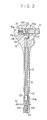
- the shift lever 2 as shown in Figs.1 to 3, comprises a control lever 14 pivotably supported by the base bracket 10, a compression rod 15 slidably positioned inside the control lever 11, a knob 16 attached to the peripheral surface of the control lever 14, and a knob button 17 inserted in the upper portion of the knob 16 in a slidable manner in the horizontal direction.
- the control lever 14 is provided with a bracket 14a at the lower portion thereof, which is rotatably supported by the base bracket 10 through a pivot shaft 19 as shown in Fig. 4.
- the cross-section of the bracket 14a is U-shaped.
- the base bracket 10 is provided with a control lever mounting portion 10a downwardly extending from the base bracket 10 and formed in a boxy shape with an opening at the upper portion. The lower end of the bracket 14a is inserted into the opening of the control lever mounting portion 10a and the lower tip of the bracket 14a is welded to a pipe 20 positioned in the horizontal direction.
- a pair of bushings 21, 21 made of synthetic resin are forcedly inserted into both sides of the pipe 20.
- the pivot shaft 19 with a head 19a is inserted into the bushings 21, 21 from one side of the control lever mounting portion 10a and the tip of the pivot shaft 19 is caulked, whereby the control lever 14 can swing in the front and rear direction (in the F-R direction in Fig. 1) about the pivot shaft 19.
- the control lever 14 is formed as a pipe structure and contains a positioning pin mounting member 23 in a freely slidable manner in the vertical direction.
- the positioning pin mounting member 23 is secured to the lower portion of the compression rod 15 and is pierced by a positioning pin 24 as a positioning member in the horizontal direction.
- the bracket 14a of the control lever 14 is provided with a pair of guide slots 14b, 14b extending in the axial direction.
- the guide slots 14b, 14b are positioned one at each side of the positioning pin mounting member 23.
- the positioning pin 24 is extended through the pair of guide slots 14a in the horizontal direction and is secured to the positioning pin mounting member 23, whereby the positioning pin 24 can move along the pair of guide slots 14b, 14b in the axial direction of the control lever 14.
- the compression rod 15 is pressed in the upper direction by a compression spring 25 through the positioning pin mounting member 23 at all times.
- the knob 16 is, as shown in Fig. 3, provided with a head portion 16a on the upper portion and the head portion 16a is provided with a lateral hole 16b.
- the knob button 17 is slidably inserted into the lateral hole 16b from the outside.
- the knob button 17 is pressed toward the outside of the lateral hole 16b by a compression spring 27 accommodated in the lateral hole 16b, so that the tip of the knob button 17 projects out of the lateral hole 16b.
- the knob button 17 is provided with a recess 17a in the head portion 16a and has a projecting portion 17b in the recess 17a.
- the recess 17a has an opening 17c at the under side and a cam member 28 is inserted into the opening 17c from the underside thereof.
- the cam member 28 is engaged by the projecting portion 17b and is secured to the upper end of the compression rod 15.
- the cam member 28 has a slope 28a contacting a slope 17d of the knob button 17, whereby when the knob button 17 is pressed into the lateral hole 16b, the cam member 28 is released from the projecting portion 17b and moves downward as the knob button 17 moves inward, and consequently, the positioning pin 24 moves downward along the guide slots 14b, 14b with the compression rod 15.
- the guide structure 3 is provided with a positioning plate 30 as a guide member for engaging the positioning pin 24 of the shift lever 2 and keeping the shift lever 2 in a parking position or a moving position.
- the positioning plate 30 is formed substantially in an L-shape in section and comprises a horizontal portion 30a secured to the base bracket 10 and a vertical portion 30b having an engaging opening 30c in the relatively rear portion.
- the positioning plate 30 is provided with a parking position and a plurality of moving positions, i.e. parking (P), reverse (R), neutral (N), drive (D), second (II) and first (I) in the shift direction, i.e. front and rear direction of the vehicle.
- the positioning plate 30 has a parking positioning recess 30d at the position corresponding to the parking position and is mounted with a buffer member 31 for absorbing the shock when the positioning pin 24 contacts the buffer member 31.
- the buffer member 31 is positioned in the position corresponding to the moving position.
- the buffer member 31 is made of synthetic resin and is formed in a reversed U-shape. For example, polyester elastomer, which has excellent elasticity and durability and is resistant to oil, is used as the synthetic resin.
- the buffer member 31 comprises a pair of circular arc sections 31a, 31b at the front corresponds to the axis of the pivot shaft 19.
- the buffer member 31 is provided with a pair of inner side sections 31c, 31d which the positioning pin 24 contacts when the positioning pin 24 is positioned in the N and II positions.
- the inner side sections 31c, 31d respectively lead to the circular arc sections31a, 31b and are connected to one another by a connecting section 31e which does not contact the positioning pin 24.
- the buffer member 31 is provided with a pair of slots 31f, 31g for buffering the shock when the positioning pin 24 contacts the inner side sections 31c, 31d.
- the slots 31f, 31g is respectively positioned close to and along the inner side sections 31f, 31g.
- the buffer member 31 may be formed by insert molding in the positioning plate 30.
- the check structure 4 is provided with the positioning plate 30 as a check member.
- the check structure has six check recesses 30e on the positioning plate 30 and a check arm 32 selectively contacting the check recesses 30e.
- the check recesses 30e are formed on a circular arc surface, of which the central point corresponds to the axis of the pivot shaft 19, formed on the peripheral surface at the front F side of the vertical section 30b of the positioning plate 30.
- the six check recesses 30e correspond to the each of the positions P, R, N, D, II and I from the front F toward the rear R.
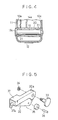
- the check arm 32 is made of synthetic resin and, as shown in Fig. 6, is pivotably supported at the base 32a by the front F side free end 14c of the bracket 14a of the control lever 14 by means of a mounting bolt 33 and a nut 34.
- a contacting roller 35 made of synthetic resin is rotatably supported by the check arm 32 through a pin 36.
- a mounting pin may be used and be caulked at the tip instead of the mounting bolt 33.
- a reinforcement cover 37 made of metal plate is attached to the check arm 32 for reinforcing the check arm 32.
- One end of a tension spring 38 engages a tab 37a of the reinforcement cover 37 and the other end engages a front F end 14d of the bracket 14a so as to press the contacting roller 35 of the check arm 32 into the check recesses 30e.
- the shift-locking device 5 comprises a rotary bushing 40 pivotably supported by a member other than the shift lever 2, a shift-lock solenoid 41 for rotating the rotary bushing 40 and a manual shift-lock release device 42 for releasing the shift lever 2 from the shift-lock condition.
- the rotary bushing 40 is made of synthetic resin and, as shown in Fig. 7, is pivotably supported by a member other than the shift lever 2, for example the horizontal portion 30a of the positioning plate 30 directly under the parking positioning recess 30d, by a pivot shaft 44.
- a projecting part 40a is mounted on the rotary bushing 40.
- the projecting part 40a is positioned right under the positioning pin 24 engaged with the parking positioning recess 30d for preventing the positioning pin 24 from disengaging from the parking positioning recess 30d.
- a tab 40b is mounted on the peripheral surface of the rotary bushing 40.
- the tab 40b has a insertion hole 40c for inserting the tip of a plunger 45 extending from the shift-lock solenoid 41.
- a lever part 40d for contacting an arm 46a of a link lever 46 of the manual shift-lock release device 42 is mounted on the peripheral surface of the rotary bushing 40.
- the shift-lock solenoid 41 is positioned in a portion on the base bracket 10.
- the shift-lock solenoid 41 is mounted on the positioning plate 30 through a bracket 47.
- the plunger 45 is always pressed toward the tip thereof by a compression spring not shown in the figure.
- the shift-lock solenoid 41 is connected to a power source through a wire 48.
- a parking switch 50 is mounted on the positioning plate 30 through a bracket 51.
- the parking switch 50 has a detecting element 52 for contacting the positioning pin 24 and detecting the shift lever 2 shifted to the P position.
- the manual shift-lock release device 42 is mounted on the shift lever 2 and is provided for releasing the shift lever 2 from the shift-lock by pressing a manual knob 54 when the shift-lock solenoid 41 cannot work because of a power failure.
- the manual knob 54 is connected to a release lever 55 contacting another arm 46b of the link lever 46.
- the link lever 46 is pivotably supported by a pivot shaft 56 so as to pivot on the pivot shaft 56 by pressing the arm 46b through release lever 55 and to press the lever part 46 by the arm 46a for pivoting the rotary bushing 40 to move the projecting part 40a from the position directly under the positioning pin 24 engaged with the parking positioning recess 30d.
- the positioning pin 24 engages the parking positioning recess 30d of the positioning plate 30 and the projecting part 40a of the rotary bushing 40 is positioned directly under the positioning pin, whereby the descent of the positioning pin 24 is blocked to shift-lock the shift lever 2.
- the contacting roller 35 of the check arm 32 is pressed and engages the check recess 30e corresponding to the P position of the positioning plate 30 by the spring force of the tension spring 38.
- the positioning pin 24 is disengaged from the parking positioning recess 60d through the cam member 28 and the compression rod 15, so that shift lever 2 may be shifted to the rear R side. Then, when the positioning pin 24 reaches the R position, the pressure on the knob button 17 is released and, as a result, the positioning pin 24 is raised by the restoring force of the compression spring 25 and engages the circular arc section 31a.
- the break pedal is released the energization of the shift-lock solenoid 41 is cancelled to project the plunger 45 by restoring force of the compression spring, so that the rotary bushing 40 is pivoted to position the projecting part 40a directly under the parking positioning recess 60d.
- the contacting roller 35 of the check arm 32 engages the check recess 30e corresponding to the R position.
- the knob button 17 is pressed to disengage the positioning pin 24 from the circular arc section 31a, and the shift lever 2 is shifted to the front F side. Then, the projecting part 40a of the rotary bushing 40 is moved from directly under the parking positioning recess 30d from pressure by the positioning pin 24. Then, when the shift lever 2 reaches the P position, the pressure to the knob button 17 is released to raise the positioning pin 24 by the spring force of the compression spring 25 and to engage the positioning pin 24 in the parking positioning recess 30d.
- the shift lever 2 When the shift lever 2 is shifted from the R position to the N, D or II position, the shift lever 2 may be shifted by simply moving the shift lever 2 to rear R side and stopping the shift lever 2 in the intended position.
- the knob button 17 is pressed as described above, then the shift lever 2 can move to rear R side, and the pressure on the knob button 17 is released when the positioning pin 24 reaches the I position.
- the rotary bushing 40 is mounted, not on the shift lever 2 as a movable member but on the positioning plate 30 as a fixed member, so that the inside diameter of the rotary bushing 40 may be small, namely the diameter of the pivot shaft 44 working as pivot of the rotary bushing 40 may be small to reduce the rotary friction, as a result the rotary bushing 40 may be prevented from producing operating noise and a working defect resulting from wobble when shift-locking.
- the diameter of the pivot shaft 44 may be small, it is not necessary for the plunger 45 of the shift-lock solenoid 41 to move to the limit of the working stroke to pivot the rotary bushing 40 by a required amount. Because the mounting space of the shift-lock solenoid 41 need not be large, it is very easy to adjust the mounting position of the shift-lock solenoid 41.
- the shift-lock solenoid 41 is mounted on the base bracket 10, for example the positioning plate 30, so that the wire 48 may be as short as possible and the number of clips for fastening the wire 48 may be small, and consequently the production costs may be reduced.
- the working space of the shift-lock solenoid 41 is not especially required, the whole device can be small.
- the buffer member 31 is made of synthetic resin, so that a shock between the positioning pin 24 and the buffer member 31 when shifting the shift lever may be absorbed by the buffer member. As a result, the positioning pin 24 and the buffer member 31 are prevented from producing a noise by metallic contact and the driver is prevented from becoming distracted by the noise.
- the buffer member 31 is provided with the slots 31f, 31g positioned close to and along the inner side sections 31f, 31g, so that the inner side sections 31f, 31g are temporarily bent when the positioning pin 24 contact the inner side sections 31f, 31g, then the inner side sections 31f, 31g regain their original shape. As a result, the buffer member 31 is prevented from producing hitting marks by the positioning pin 24.
- the check arm 32 and the contacting roller 35 are made of synthetic resin, so that when the contacting roller 35 contacts the check recess 30e, a driver is prevented from being distracted by the noise produced by metallic contact.
Landscapes
- Engineering & Computer Science (AREA)
- General Engineering & Computer Science (AREA)
- Mechanical Engineering (AREA)
- Arrangement Or Mounting Of Control Devices For Change-Speed Gearing (AREA)
- Control Of Transmission Device (AREA)
Applications Claiming Priority (6)
| Application Number | Priority Date | Filing Date | Title |
|---|---|---|---|
| JP13851990A JPH0434264A (ja) | 1990-05-30 | 1990-05-30 | オートマチックトランスミッションコントロールデバイスのシフトロック構造 |
| JP138519/90 | 1990-05-30 | ||
| JP1990055925U JP2570807Y2 (ja) | 1990-05-30 | 1990-05-30 | 自動変速機用シフトレバー装置 |
| JP55925/90U | 1990-05-30 | ||
| JP13851890A JPH0434263A (ja) | 1990-05-30 | 1990-05-30 | 自動変速機用シフトレバー装置 |
| JP138518/90 | 1990-05-30 |
Publications (2)
| Publication Number | Publication Date |
|---|---|
| EP0459485A1 true EP0459485A1 (de) | 1991-12-04 |
| EP0459485B1 EP0459485B1 (de) | 1995-08-23 |
Family
ID=27295744
Family Applications (1)
| Application Number | Title | Priority Date | Filing Date |
|---|---|---|---|
| EP91108869A Expired - Lifetime EP0459485B1 (de) | 1990-05-30 | 1991-05-29 | Schalteinrichtung eines automatischen Getriebes |
Country Status (3)
| Country | Link |
|---|---|
| US (1) | US5207740A (de) |
| EP (1) | EP0459485B1 (de) |
| DE (1) | DE69112278T2 (de) |
Cited By (5)
| Publication number | Priority date | Publication date | Assignee | Title |
|---|---|---|---|---|
| EP0823571A3 (de) * | 1996-08-09 | 1998-08-19 | Mannoh Kogyo Co., Ltd. | Lenkradschalthebel für automatisches Getriebe |
| US5938562A (en) * | 1998-02-17 | 1999-08-17 | Pontiac Coil, Inc. | Brake shifter interlock with improved park lock switch |
| EP0939251A3 (de) * | 1998-02-27 | 2000-02-02 | Fuji Kiko Company Limited | Schalthebel |
| US6298743B1 (en) | 1997-07-11 | 2001-10-09 | Hkr Haas Gmbh & Co. Kunstsoff Kg | Selector lever for an automatic gearbox |
| EP1170655A3 (de) * | 2000-06-27 | 2002-11-20 | Fujikiko Kabushiki Kaisha | Schaltungseinrichtung für ein Übertragungssystem |
Families Citing this family (13)
| Publication number | Priority date | Publication date | Assignee | Title |
|---|---|---|---|---|
| US5431266A (en) * | 1992-12-02 | 1995-07-11 | Nissan Motor Co., Ltd. | Shift lock system |
| JPH06229467A (ja) * | 1993-02-02 | 1994-08-16 | Fuji Kiko Co Ltd | シフトロック装置 |
| JP3396094B2 (ja) * | 1994-09-30 | 2003-04-14 | 富士機工株式会社 | 自動変速機操作装置 |
| USD390179S (en) | 1995-12-11 | 1998-02-03 | Dr. Ing. H.C.F. Porsche Ag | Hand brake lever |
| USD384926S (en) * | 1996-08-12 | 1997-10-14 | B&M Automotive Products | Transmission shifter |
| JP4199714B2 (ja) * | 2004-09-02 | 2008-12-17 | 本田技研工業株式会社 | シフト装置及びその制御方法 |
| JP4944702B2 (ja) * | 2007-08-16 | 2012-06-06 | 株式会社クボタ | 静油圧式無段変速装置の中立付勢装置 |
| DE102009034695A1 (de) * | 2009-07-24 | 2011-01-27 | GM Global Technology Operations, Inc., Detroit | Wählhebel für Wechselgetriebe |
| JP5261446B2 (ja) | 2010-07-28 | 2013-08-14 | 株式会社クボタ | 静油圧式無段変速装置の中立付勢装置 |
| KR101355617B1 (ko) * | 2012-10-26 | 2014-01-27 | 현대자동차주식회사 | 변속 레버 |
| US9476500B2 (en) | 2013-09-30 | 2016-10-25 | Kongsberg Driveline Systems I, Inc | Manual gear shifter assembly |
| JP2017109510A (ja) * | 2015-12-14 | 2017-06-22 | トヨタ自動車株式会社 | シフトレバー装置 |
| CN114162545B (zh) * | 2020-09-11 | 2022-08-30 | 同方威视技术股份有限公司 | 用于多车位车辆安检系统的载车板环路运输系统及方法 |
Citations (2)
| Publication number | Priority date | Publication date | Assignee | Title |
|---|---|---|---|---|
| DE3048093A1 (de) * | 1979-12-21 | 1981-09-17 | Nissan Motor Co., Ltd., Yokohama, Kanagawa | Schalthebelmechanismus eines automatischen getriebes |
| EP0307846A1 (de) * | 1987-09-14 | 1989-03-22 | Kabushiki Kaisha Tokai Rika Denki Seisakusho | Einrichtung zum Sperren des Schalthebels eines automatischen Getriebes |
Family Cites Families (8)
| Publication number | Priority date | Publication date | Assignee | Title |
|---|---|---|---|---|
| JPS57134331A (en) * | 1981-02-09 | 1982-08-19 | Nissan Motor Co Ltd | Controller for automatic speed change gear |
| US4612820A (en) * | 1985-06-03 | 1986-09-23 | Chrysler Corporation | Automatic transmission shift selector mechanism |
| DE3850929T2 (de) * | 1987-10-16 | 1994-12-01 | Fuji Kiko Kk | Wählhebelsperre für Automatikgetriebe. |
| AU605010B2 (en) * | 1988-01-14 | 1991-01-03 | Kabushiki Kaisha Tokai-Rika-Denki-Seisakusho | Transmission operating apparatus |
| JPH0611219Y2 (ja) * | 1988-12-22 | 1994-03-23 | トヨタ自動車株式会社 | 車両の自動変速機用シフトレバー装置 |
| EP0378244A3 (de) * | 1989-01-13 | 1990-09-12 | Nissan Motor Co., Ltd. | Steuerungsanlage für automatische Fahrzeuggetriebe |
| JP2860110B2 (ja) * | 1989-05-08 | 1999-02-24 | 日産自動車株式会社 | オートマチックトランスミッションのコントロールデバイス |
| US5085096A (en) * | 1989-12-11 | 1992-02-04 | Chrysler Corporation | Gearshift park interlock system |
-
1991
- 1991-05-28 US US07/706,951 patent/US5207740A/en not_active Expired - Fee Related
- 1991-05-29 DE DE69112278T patent/DE69112278T2/de not_active Expired - Fee Related
- 1991-05-29 EP EP91108869A patent/EP0459485B1/de not_active Expired - Lifetime
Patent Citations (2)
| Publication number | Priority date | Publication date | Assignee | Title |
|---|---|---|---|---|
| DE3048093A1 (de) * | 1979-12-21 | 1981-09-17 | Nissan Motor Co., Ltd., Yokohama, Kanagawa | Schalthebelmechanismus eines automatischen getriebes |
| EP0307846A1 (de) * | 1987-09-14 | 1989-03-22 | Kabushiki Kaisha Tokai Rika Denki Seisakusho | Einrichtung zum Sperren des Schalthebels eines automatischen Getriebes |
Cited By (7)
| Publication number | Priority date | Publication date | Assignee | Title |
|---|---|---|---|---|
| EP0823571A3 (de) * | 1996-08-09 | 1998-08-19 | Mannoh Kogyo Co., Ltd. | Lenkradschalthebel für automatisches Getriebe |
| US6298743B1 (en) | 1997-07-11 | 2001-10-09 | Hkr Haas Gmbh & Co. Kunstsoff Kg | Selector lever for an automatic gearbox |
| US5938562A (en) * | 1998-02-17 | 1999-08-17 | Pontiac Coil, Inc. | Brake shifter interlock with improved park lock switch |
| EP0939251A3 (de) * | 1998-02-27 | 2000-02-02 | Fuji Kiko Company Limited | Schalthebel |
| US6189398B1 (en) | 1998-02-27 | 2001-02-20 | Fuji Koko Co., Ltd. | Shift-lever devices |
| EP1170655A3 (de) * | 2000-06-27 | 2002-11-20 | Fujikiko Kabushiki Kaisha | Schaltungseinrichtung für ein Übertragungssystem |
| US6732608B2 (en) | 2000-06-27 | 2004-05-11 | Fujikiko Kabushiki Kaisha | Shift knob and shift lever |
Also Published As
| Publication number | Publication date |
|---|---|
| EP0459485B1 (de) | 1995-08-23 |
| DE69112278D1 (de) | 1995-09-28 |
| US5207740A (en) | 1993-05-04 |
| DE69112278T2 (de) | 1996-02-01 |
Similar Documents
| Publication | Publication Date | Title |
|---|---|---|
| US5207740A (en) | Control device for automatic transmission | |
| EP0760917B1 (de) | Schaltmechanismus zum manuellen schalten eines automatischen getriebes | |
| JP3889951B2 (ja) | 多段自動変速機操作装置 | |
| US6325196B1 (en) | Shifter with park lock and neutral lock device | |
| US5497673A (en) | Automatic transmission operating device | |
| US5186069A (en) | Control device for automatic transmission | |
| EP0978669B1 (de) | Schalthebel mit Handschalt- und Automatikmodus für Automatikgetriebe | |
| US5016738A (en) | Automatic transmission shift control device | |
| US6783480B2 (en) | Control device for automatic transmission | |
| EP0748958B1 (de) | Schaltsperrmechanismus für Schalthebel | |
| US4660443A (en) | Transmission selector lever assembly | |
| EP0939251B1 (de) | Schalthebel | |
| JP2003191766A (ja) | 自動変速機操作装置のシフトロック機構 | |
| US5339705A (en) | Shift device for automatic transmission | |
| US6789444B2 (en) | Shift lever device with locking mechanism | |
| US5015807A (en) | Shift lever apparatus for automotive vehicles | |
| US6378395B1 (en) | Column shift device with key interlock mechanism | |
| KR100461377B1 (ko) | 자동 변속기의 시프트 록 장치 | |
| EP0823571A2 (de) | Lenkradschalthebel für automatisches Getriebe | |
| JP4633385B2 (ja) | 変速機のチェンジ機構 | |
| JPH0653853U (ja) | シフトロックの空振り機構 | |
| JP2564854Y2 (ja) | 自動変速機用シフトレバー装置 | |
| JPH0434264A (ja) | オートマチックトランスミッションコントロールデバイスのシフトロック構造 | |
| WO2003025694A1 (en) | A shift lever assembly | |
| JPH0434263A (ja) | 自動変速機用シフトレバー装置 |
Legal Events
| Date | Code | Title | Description |
|---|---|---|---|
| PUAI | Public reference made under article 153(3) epc to a published international application that has entered the european phase |
Free format text: ORIGINAL CODE: 0009012 |
|
| 17P | Request for examination filed |
Effective date: 19910529 |
|
| AK | Designated contracting states |
Kind code of ref document: A1 Designated state(s): DE GB |
|
| RIN1 | Information on inventor provided before grant (corrected) |
Inventor name: SAKON, HIROSHI Inventor name: TOGANO, NORIO Inventor name: KATAUMI, YOSHIMASA Inventor name: ASANO, YASUSHI Inventor name: OHNO, ATSUO C/O NISSAN MOTOR CO., LTD. Inventor name: IKUSHIMA, SHUNSUKE C/O NISSAN MOTOR CO., LTD. |
|
| 17Q | First examination report despatched |
Effective date: 19930806 |
|
| GRAA | (expected) grant |
Free format text: ORIGINAL CODE: 0009210 |
|
| AK | Designated contracting states |
Kind code of ref document: B1 Designated state(s): DE GB |
|
| REF | Corresponds to: |
Ref document number: 69112278 Country of ref document: DE Date of ref document: 19950928 |
|
| PLBE | No opposition filed within time limit |
Free format text: ORIGINAL CODE: 0009261 |
|
| STAA | Information on the status of an ep patent application or granted ep patent |
Free format text: STATUS: NO OPPOSITION FILED WITHIN TIME LIMIT |
|
| 26N | No opposition filed | ||
| PGFP | Annual fee paid to national office [announced via postgrant information from national office to epo] |
Ref country code: GB Payment date: 19980427 Year of fee payment: 8 |
|
| PGFP | Annual fee paid to national office [announced via postgrant information from national office to epo] |
Ref country code: DE Payment date: 19980610 Year of fee payment: 8 |
|
| PG25 | Lapsed in a contracting state [announced via postgrant information from national office to epo] |
Ref country code: GB Free format text: LAPSE BECAUSE OF NON-PAYMENT OF DUE FEES Effective date: 19990529 |
|
| GBPC | Gb: european patent ceased through non-payment of renewal fee |
Effective date: 19990529 |
|
| PG25 | Lapsed in a contracting state [announced via postgrant information from national office to epo] |
Ref country code: DE Free format text: LAPSE BECAUSE OF NON-PAYMENT OF DUE FEES Effective date: 20000301 |