EP0459497A2 - Ventilateur hélicoide avec boîtier cylindrique - Google Patents
Ventilateur hélicoide avec boîtier cylindrique Download PDFInfo
- Publication number
- EP0459497A2 EP0459497A2 EP91108890A EP91108890A EP0459497A2 EP 0459497 A2 EP0459497 A2 EP 0459497A2 EP 91108890 A EP91108890 A EP 91108890A EP 91108890 A EP91108890 A EP 91108890A EP 0459497 A2 EP0459497 A2 EP 0459497A2
- Authority
- EP
- European Patent Office
- Prior art keywords
- axial fan
- hub
- fan according
- cross
- section
- Prior art date
- Legal status (The legal status is an assumption and is not a legal conclusion. Google has not performed a legal analysis and makes no representation as to the accuracy of the status listed.)
- Granted
Links
Images
Classifications
-
- F—MECHANICAL ENGINEERING; LIGHTING; HEATING; WEAPONS; BLASTING
- F04—POSITIVE - DISPLACEMENT MACHINES FOR LIQUIDS; PUMPS FOR LIQUIDS OR ELASTIC FLUIDS
- F04D—NON-POSITIVE-DISPLACEMENT PUMPS
- F04D25/00—Pumping installations or systems
- F04D25/02—Units comprising pumps and their driving means
- F04D25/06—Units comprising pumps and their driving means the pump being electrically driven
- F04D25/0606—Units comprising pumps and their driving means the pump being electrically driven the electric motor being specially adapted for integration in the pump
-
- F—MECHANICAL ENGINEERING; LIGHTING; HEATING; WEAPONS; BLASTING
- F04—POSITIVE - DISPLACEMENT MACHINES FOR LIQUIDS; PUMPS FOR LIQUIDS OR ELASTIC FLUIDS
- F04D—NON-POSITIVE-DISPLACEMENT PUMPS
- F04D29/00—Details, component parts, or accessories
- F04D29/26—Rotors specially for elastic fluids
- F04D29/32—Rotors specially for elastic fluids for axial flow pumps
- F04D29/38—Blades
- F04D29/384—Blades characterised by form
-
- Y—GENERAL TAGGING OF NEW TECHNOLOGICAL DEVELOPMENTS; GENERAL TAGGING OF CROSS-SECTIONAL TECHNOLOGIES SPANNING OVER SEVERAL SECTIONS OF THE IPC; TECHNICAL SUBJECTS COVERED BY FORMER USPC CROSS-REFERENCE ART COLLECTIONS [XRACs] AND DIGESTS
- Y10—TECHNICAL SUBJECTS COVERED BY FORMER USPC
- Y10S—TECHNICAL SUBJECTS COVERED BY FORMER USPC CROSS-REFERENCE ART COLLECTIONS [XRACs] AND DIGESTS
- Y10S416/00—Fluid reaction surfaces, i.e. impellers
- Y10S416/02—Formulas of curves
-
- Y—GENERAL TAGGING OF NEW TECHNOLOGICAL DEVELOPMENTS; GENERAL TAGGING OF CROSS-SECTIONAL TECHNOLOGIES SPANNING OVER SEVERAL SECTIONS OF THE IPC; TECHNICAL SUBJECTS COVERED BY FORMER USPC CROSS-REFERENCE ART COLLECTIONS [XRACs] AND DIGESTS
- Y10—TECHNICAL SUBJECTS COVERED BY FORMER USPC
- Y10S—TECHNICAL SUBJECTS COVERED BY FORMER USPC CROSS-REFERENCE ART COLLECTIONS [XRACs] AND DIGESTS
- Y10S416/00—Fluid reaction surfaces, i.e. impellers
- Y10S416/05—Variable camber or chord length
Definitions
- the invention relates to an axial fan with a substantially cylindrical outer housing and a fan wheel revolving therein, the hub of which is seated on the rotor of a centrally arranged electric drive motor, the stator of which is held by webs which extend on the pressure side to the outer housing, and the radially twisted blades of which have a forward curvature with a curvature that changes from the cross section to the outer cross section.
- Such fans are installed to generate a cooling air flow, for example in personal computers and other electronic devices. Since such devices are often operated at desks and comparable workplaces, the noise development, which is associated with the generation of the cooling air flow plays a significant role. For fans of the type described at the outset, the task is therefore not only to generate a sufficient volume flow at such a pressure increase which is sufficient to overcome the flow resistance specified by the device construction, but also to cause as little working noise as possible. Furthermore, the need to reduce manufacturing costs has led to the manufacture of both the outer housing and the fan wheel from injection-molded plastic, whereas in the past the outer housing was die-cast from metal and the fan wheel was welded from sheet metal; this in turn has consequences for the design of the fan.
- the fan wheel of the known fan described at the outset has seven blades, the cross-section of which is designed in every circumferential plane from the hub to the outer edge for the same characteristic point - that is, the same volume flow at a certain pressure increase.
- the wing cross-section in the hub area has a strong curvature and at the same time a large setting angle (against the axis perpendicular); towards the outside, both the curvature and the setting angle decrease.
- the cross section lengthens in accordance with the increasing scope.
- this fan was only able to meet the expectations placed on it to a limited extent.
- the volume flow with free-blowing operation seemed to indicate the generation of sufficient air circulation, the practical use showed realistic Conditions that the pressure increase was not sufficient to maintain the required volume flow even against the resistance at the place of use.
- the aim of the invention was therefore to design an axial fan of the present type in such a way that, with the greatest possible reduction in operating noise, an increase in pressure is achieved which maintains the required volume flow of air even under installation conditions.
- vanes in the hub area have a cross section designed for small volume flow and small pressure increase, in the outer area, on the other hand, a cross section designed for higher volume flow and pressure increase values, while the cross-sectional design in the area in between changes continuously and the vanes relatively small change in curvature are also slightly twisted overall.
- the front edges starting from the hub, initially curve radially and further outward with the direction of rotation, while preferably the rear edges are inclined forwardly against the hub and are curved outward of the central section against the direction of rotation.
- the wings are particularly preferably arranged in an odd number on the handle because this eliminates noises which otherwise occur in even-numbered wings due to the even-numbered division of the circumference.
- the stator of the electric drive motor is also particularly preferably held by an even number of webs on the outer housing, as a result of which the undesired noises can be further reduced.
- the forward curvature of the vanes particularly preferably decreases with increasing distance from the hub, within a cross-section of the vanes, that is to say at a constant one Distance from the hub, preferably the forward curvature increases towards the rear edge of the wings. It has been shown that such a shape particularly advantageously realizes the radial dependence of the volume flow and the pressure increase according to the invention.
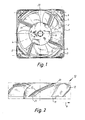
- the outer housing 1 of the axial fan consists of one piece and has a cylindrical section 2, which is delimited on the end face by molded-on, mutually aligned flange sections 3. In the corner areas of the pressure side, the cylindrical section 2 merges into extensions 4. In these, for example, there are four webs 5 which - parallel to the circumference - run parallel to the radius and open into a central plate 6 which carries the stator (not shown) of the (electric) drive motor. Holes 7 in the corners of the flanges 3 are used to fasten the fan, for example in a monitor housing.
- the fan wheel designated as a whole by 10, has a hub 11, the diameter of which is substantially equal to the diameter of the plate 6, and which cup-shaped engages over the stator of the electric motor fastened on the plate 6 and is in operative connection with its rotor part.
- the fan blades 12 with the hub 11 are made in one piece, which is produced in a plastic injection molding process.
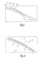
- FIG. 3 illustrates the different cross-sectional configuration of the blades in radially different circumferential planes (in the opposite direction of rotation; cf. direction of rotation arrow 8) more clearly than the top view of the middle blade 12 in FIG. 2.
- the wing 12 attaches to the hub 11 in the hub region.
- the middle profile shows the cross section 14, and the cross section 15 strongly outlined in FIG. 3 illustrates the wing profile on the outer circumference of the fan wheel. It shows that both the curvature, namely the greatest distance of the wing inner profile from the edge connecting 16 and the setting angle of this edge connecting relative to the perpendicular 17 to the axis 18, changes only slightly in the three cross-sectional (circumferential) planes.
- the curvature has the shape of a forward curvature, which decreases with increasing distance from the hub 11.
- the forward curvature - viewed in cross section of a wing - increases steadily from the front edge 20 to the rear edge 21.
- This configuration of the vane 12 results if the radially inner vane profile (in the hub area) is given smaller values for volume flow and pressure increase than the configuration determination of the cross-section on the outer diameter when designing the profile; a suitable interpolation takes place in between.
- FIG. 4 shows the corresponding cross-sectional configurations 13a, 14a and 15a of a wing which has been given the same characteristic values over its entire radial extent.
- the top view of the impeller 10 in FIG. 1 illustrates the crescent shape of the leading edges 20 and the trailing edges 21 of each wing 12.
- the leading edges 20 initially run radially outward and then are curved against the direction of rotation, while the trailing edges 21 start tilted backwards on the hub 11 and run outward of the wing center section with the direction of rotation curved.
- the wing cross section 14 has the greatest length in the central section (FIG. 3).
Landscapes
- Engineering & Computer Science (AREA)
- Mechanical Engineering (AREA)
- General Engineering & Computer Science (AREA)
- Structures Of Non-Positive Displacement Pumps (AREA)
Applications Claiming Priority (2)
| Application Number | Priority Date | Filing Date | Title |
|---|---|---|---|
| DE9006174U DE9006174U1 (de) | 1990-05-31 | 1990-05-31 | Axiallüfter mit zylindrischem Außengehäuse |
| DE9006174U | 1990-05-31 |
Publications (3)
| Publication Number | Publication Date |
|---|---|
| EP0459497A2 true EP0459497A2 (fr) | 1991-12-04 |
| EP0459497A3 EP0459497A3 (en) | 1992-02-26 |
| EP0459497B1 EP0459497B1 (fr) | 1994-06-22 |
Family
ID=6854287
Family Applications (1)
| Application Number | Title | Priority Date | Filing Date |
|---|---|---|---|
| EP91108890A Expired - Lifetime EP0459497B1 (fr) | 1990-05-31 | 1991-05-31 | Ventilateur hélicoide avec boîtier cylindrique |
Country Status (4)
| Country | Link |
|---|---|
| US (1) | US5184938A (fr) |
| EP (1) | EP0459497B1 (fr) |
| AT (1) | ATE107743T1 (fr) |
| DE (2) | DE9006174U1 (fr) |
Cited By (3)
| Publication number | Priority date | Publication date | Assignee | Title |
|---|---|---|---|---|
| EP0583091A3 (fr) * | 1992-07-22 | 1994-04-13 | Valeo Thermique Moteur Sa | |
| EP0955467A3 (fr) * | 1998-05-04 | 2001-03-28 | Carrier Corporation | Ventilateur axial avec boíte d'une pièce |
| EP3982518A1 (fr) * | 2020-10-06 | 2022-04-13 | mdGroup Germany GmbH | Rotor et procédé de montage d'un rotor |
Families Citing this family (18)
| Publication number | Priority date | Publication date | Assignee | Title |
|---|---|---|---|---|
| DE4127134B4 (de) * | 1991-08-15 | 2004-07-08 | Papst Licensing Gmbh & Co. Kg | Diagonallüfter |
| USD368772S (en) | 1993-10-08 | 1996-04-09 | Harries Liao | Fan wheel |
| CH687637A5 (de) * | 1993-11-04 | 1997-01-15 | Micronel Ag | Axialkleinventilator. |
| USD368224S (en) | 1994-08-31 | 1996-03-26 | Arndt Peter L | Lid for containers for waste filters |
| US5616004A (en) * | 1995-04-19 | 1997-04-01 | Valeo Thermique Moteur | Axial flow fan |
| US5957661A (en) * | 1998-06-16 | 1999-09-28 | Siemens Canada Limited | High efficiency to diameter ratio and low weight axial flow fan |
| US6386830B1 (en) | 2001-03-13 | 2002-05-14 | The United States Of America As Represented By The Secretary Of The Navy | Quiet and efficient high-pressure fan assembly |
| US6457941B1 (en) | 2001-03-13 | 2002-10-01 | The United States Of America As Represented By The Secretary Of The Navy | Fan rotor with construction and safety performance optimization |
| US6722849B1 (en) | 2002-03-08 | 2004-04-20 | Emerson Electric Co. | Propeller for tubeaxial fan |
| US6945758B1 (en) * | 2002-03-08 | 2005-09-20 | Emerson Electric Co. | Drive support and cover assembly for tubeaxial fan |
| US6702548B1 (en) | 2002-03-08 | 2004-03-09 | Emerson Electric Co. | Tubeaxial fan assembly |
| US7249931B2 (en) * | 2002-03-30 | 2007-07-31 | University Of Central Florida Research Foundation, Inc. | High efficiency air conditioner condenser fan with performance enhancements |
| US8647077B2 (en) * | 2004-02-20 | 2014-02-11 | Hewlett-Packard Development Company, L.P. | Cooling fan for electronic device |
| USD561888S1 (en) * | 2006-12-28 | 2008-02-12 | Foxconn Technology Co., Ltd. | Impeller |
| DE202008002356U1 (de) * | 2008-02-19 | 2009-06-25 | Ebm-Papst Mulfingen Gmbh & Co. Kg | Kompaktlüfter |
| JP2013209956A (ja) * | 2012-03-30 | 2013-10-10 | Sanyo Denki Co Ltd | 軸流ファン |
| USD723151S1 (en) * | 2013-12-13 | 2015-02-24 | Cooler Master Co., Ltd. | Fan |
| US10578126B2 (en) | 2016-04-26 | 2020-03-03 | Acme Engineering And Manufacturing Corp. | Low sound tubeaxial fan |
Family Cites Families (19)
| Publication number | Priority date | Publication date | Assignee | Title |
|---|---|---|---|---|
| AT115470B (de) * | 1925-09-21 | 1929-12-27 | Voith J M Fa | Laufradschaufel für Kreiselmaschinen. |
| US1964525A (en) * | 1932-07-30 | 1934-06-26 | Gen Electric | Fan blade |
| US2524870A (en) * | 1944-11-06 | 1950-10-10 | James Russell Kennedy | Screw fan, pump, or other cased or uncased screw wheel |
| US2578806A (en) * | 1949-06-04 | 1951-12-18 | Johnson Lawrence | Propeller |
| GB683012A (en) * | 1951-03-06 | 1952-11-19 | Oscar Abraham Wirkkala | Improvements in or relating to screw propellers |
| AT203428B (de) * | 1957-01-30 | 1959-05-11 | Ernst Dr Ing Souczek | Laufrad für axiale Strömungsmaschinen, insbesondere Wasserturbinen |
| US3023709A (en) * | 1958-05-26 | 1962-03-06 | Kondo Masukichi | Vanes of an impeller for axial flow propeller pumps |
| DE1964890A1 (de) * | 1969-12-24 | 1971-07-01 | Papst Motoren Kg | Ventilator-Einheit mit Elektronik-Bauteilen |
| DE2226177A1 (de) * | 1972-05-30 | 1973-12-13 | Benzing Ventilatoren Ohg | Ventilator, insbesondere zur entlueftung von kleinen raeumen |
| US4063852A (en) * | 1976-01-28 | 1977-12-20 | Torin Corporation | Axial flow impeller with improved blade shape |
| JPS53115911A (en) * | 1977-03-19 | 1978-10-09 | Daikin Ind Ltd | Axial-flow fan |
| US4142844A (en) * | 1977-05-31 | 1979-03-06 | Allware Agencies Ltd. | Fan blade assemblies for box fans |
| US4358245A (en) * | 1980-09-18 | 1982-11-09 | Bolt Beranek And Newman Inc. | Low noise fan |
| US4569631A (en) * | 1984-08-06 | 1986-02-11 | Airflow Research And Manufacturing Corp. | High strength fan |
| EP0174487A1 (fr) * | 1984-08-16 | 1986-03-19 | Siemens Aktiengesellschaft | Ventilateur axial |
| CH667901A5 (de) * | 1985-05-02 | 1988-11-15 | Papst Motoren Gmbh & Co Kg | Einbauventilator. |
| IT206701Z2 (it) * | 1985-08-02 | 1987-10-01 | Gate Spa | Ventilatore assiale particolarmente per autoveicoli |
| JP2590514B2 (ja) * | 1987-03-13 | 1997-03-12 | 日本電装株式会社 | 送風ファン |
| DE8705665U1 (de) * | 1987-04-16 | 1987-06-11 | Knürr-Mechanik für die Elektronik AG, 8000 München | Lüftereinschub |
-
1990
- 1990-05-31 DE DE9006174U patent/DE9006174U1/de not_active Expired - Lifetime
-
1991
- 1991-05-30 US US07/708,132 patent/US5184938A/en not_active Expired - Lifetime
- 1991-05-31 AT AT91108890T patent/ATE107743T1/de not_active IP Right Cessation
- 1991-05-31 EP EP91108890A patent/EP0459497B1/fr not_active Expired - Lifetime
- 1991-05-31 DE DE59101986T patent/DE59101986D1/de not_active Expired - Lifetime
Cited By (4)
| Publication number | Priority date | Publication date | Assignee | Title |
|---|---|---|---|---|
| EP0583091A3 (fr) * | 1992-07-22 | 1994-04-13 | Valeo Thermique Moteur Sa | |
| EP0955467A3 (fr) * | 1998-05-04 | 2001-03-28 | Carrier Corporation | Ventilateur axial avec boíte d'une pièce |
| EP3982518A1 (fr) * | 2020-10-06 | 2022-04-13 | mdGroup Germany GmbH | Rotor et procédé de montage d'un rotor |
| US12146505B2 (en) | 2020-10-06 | 2024-11-19 | Mdgroup Germany Gmbh | Impeller machine and method for mounting an impeller machine |
Also Published As
| Publication number | Publication date |
|---|---|
| EP0459497B1 (fr) | 1994-06-22 |
| US5184938A (en) | 1993-02-09 |
| EP0459497A3 (en) | 1992-02-26 |
| DE9006174U1 (de) | 1991-10-10 |
| DE59101986D1 (de) | 1994-07-28 |
| ATE107743T1 (de) | 1994-07-15 |
Similar Documents
| Publication | Publication Date | Title |
|---|---|---|
| EP0459497B1 (fr) | Ventilateur hélicoide avec boîtier cylindrique | |
| EP0786597B1 (fr) | Soufflante radial | |
| DE68907555T2 (de) | Verflüssigende Kreiselpumpe oder Laufrad für solche Pumpe. | |
| DE3044920C2 (de) | Diffusor für Radialverdichter | |
| DE4006604C2 (fr) | ||
| DE69932206T2 (de) | Kreiselverdichter | |
| DE1428191A1 (de) | Kreiselgeblaese | |
| DE2744366A1 (de) | Laufrad fuer einen radialen turboverdichter | |
| DE202011004708U1 (de) | Ventilator | |
| DE102004023270A1 (de) | Axialschraubengebläse | |
| DE19850461A1 (de) | Gebläselaufrad, sowie Gebläse hiermit | |
| DE3614806A1 (de) | Einbauventilator | |
| DE1453730A1 (de) | Radialpumpe | |
| DE9016767U1 (de) | Dunstabzugshaube | |
| DE1924611A1 (de) | Geblaese | |
| EP2329149B1 (fr) | Ventilateur diagonal | |
| DE69209484T2 (de) | Lüfter mit konvexen Schaufeln | |
| DE102019134354A1 (de) | Elektromotorvorrichtung mit einem Elektromotor und einer integralen Gebläsevorrichtung | |
| CH650563A5 (en) | Diffuser in a centrifugal driven machine | |
| DE1945979A1 (de) | Geblaese | |
| DE102021204491A1 (de) | Ventilator, insbesondere Radial- oder Diagonalventilator | |
| DE10019820C2 (de) | Pumpe, insbesondere Umwälzpumpe für Haushaltsmaschinen wie Geschirrspülmaschinen | |
| WO2013143671A1 (fr) | Ventilateur, notamment pour un usage dans le domaine technique de la climatisation et du froid | |
| DE2223066A1 (de) | Geblaeseeinheit, vorzugsweise fuer oel- oder gasbrenner | |
| EP3738634B1 (fr) | Appareil de thérapie respiratoire et roue de ventilateur pour un appareil de thérapie respiratoire |
Legal Events
| Date | Code | Title | Description |
|---|---|---|---|
| PUAI | Public reference made under article 153(3) epc to a published international application that has entered the european phase |
Free format text: ORIGINAL CODE: 0009012 |
|
| AK | Designated contracting states |
Kind code of ref document: A2 Designated state(s): AT CH DE ES FR GB IT LI NL |
|
| PUAL | Search report despatched |
Free format text: ORIGINAL CODE: 0009013 |
|
| AK | Designated contracting states |
Kind code of ref document: A3 Designated state(s): AT CH DE ES FR GB IT LI NL |
|
| 17P | Request for examination filed |
Effective date: 19920822 |
|
| 17Q | First examination report despatched |
Effective date: 19930609 |
|
| GRAA | (expected) grant |
Free format text: ORIGINAL CODE: 0009210 |
|
| AK | Designated contracting states |
Kind code of ref document: B1 Designated state(s): AT CH DE ES FR GB IT LI NL |
|
| PG25 | Lapsed in a contracting state [announced via postgrant information from national office to epo] |
Ref country code: IT Free format text: LAPSE BECAUSE OF FAILURE TO SUBMIT A TRANSLATION OF THE DESCRIPTION OR TO PAY THE FEE WITHIN THE PRESCRIBED TIME-LIMIT;WARNING: LAPSES OF ITALIAN PATENTS WITH EFFECTIVE DATE BEFORE 2007 MAY HAVE OCCURRED AT ANY TIME BEFORE 2007. THE CORRECT EFFECTIVE DATE MAY BE DIFFERENT FROM THE ONE RECORDED. Effective date: 19940622 Ref country code: ES Free format text: THE PATENT HAS BEEN ANNULLED BY A DECISION OF A NATIONAL AUTHORITY Effective date: 19940622 Ref country code: FR Effective date: 19940622 Ref country code: NL Effective date: 19940622 |
|
| REF | Corresponds to: |
Ref document number: 107743 Country of ref document: AT Date of ref document: 19940715 Kind code of ref document: T |
|
| REF | Corresponds to: |
Ref document number: 59101986 Country of ref document: DE Date of ref document: 19940728 |
|
| GBT | Gb: translation of ep patent filed (gb section 77(6)(a)/1977) |
Effective date: 19940916 |
|
| EN | Fr: translation not filed | ||
| NLV1 | Nl: lapsed or annulled due to failure to fulfill the requirements of art. 29p and 29m of the patents act | ||
| REG | Reference to a national code |
Ref country code: GB Ref legal event code: 732E |
|
| RAP2 | Party data changed (patent owner data changed or rights of a patent transferred) |
Owner name: PAPST LICENSING GMBH |
|
| PLBE | No opposition filed within time limit |
Free format text: ORIGINAL CODE: 0009261 |
|
| STAA | Information on the status of an ep patent application or granted ep patent |
Free format text: STATUS: NO OPPOSITION FILED WITHIN TIME LIMIT |
|
| PG25 | Lapsed in a contracting state [announced via postgrant information from national office to epo] |
Ref country code: AT Effective date: 19950531 Ref country code: CH Effective date: 19950531 Ref country code: LI Effective date: 19950531 |
|
| 26N | No opposition filed | ||
| REG | Reference to a national code |
Ref country code: CH Ref legal event code: PUE Owner name: PAPST LICENSING GMBH |
|
| REG | Reference to a national code |
Ref country code: CH Ref legal event code: PL |
|
| REG | Reference to a national code |
Ref country code: GB Ref legal event code: IF02 |
|
| PGFP | Annual fee paid to national office [announced via postgrant information from national office to epo] |
Ref country code: GB Payment date: 20090303 Year of fee payment: 19 |
|
| PGFP | Annual fee paid to national office [announced via postgrant information from national office to epo] |
Ref country code: DE Payment date: 20100723 Year of fee payment: 20 |
|
| GBPC | Gb: european patent ceased through non-payment of renewal fee |
Effective date: 20100531 |
|
| REG | Reference to a national code |
Ref country code: DE Ref legal event code: R071 Ref document number: 59101986 Country of ref document: DE |
|
| PG25 | Lapsed in a contracting state [announced via postgrant information from national office to epo] |
Ref country code: GB Free format text: LAPSE BECAUSE OF NON-PAYMENT OF DUE FEES Effective date: 20100531 |
|
| PG25 | Lapsed in a contracting state [announced via postgrant information from national office to epo] |
Ref country code: DE Free format text: LAPSE BECAUSE OF EXPIRATION OF PROTECTION Effective date: 20110601 |