EP0459528B1 - Sèche-cheveux - Google Patents
Sèche-cheveux Download PDFInfo
- Publication number
- EP0459528B1 EP0459528B1 EP91111014A EP91111014A EP0459528B1 EP 0459528 B1 EP0459528 B1 EP 0459528B1 EP 91111014 A EP91111014 A EP 91111014A EP 91111014 A EP91111014 A EP 91111014A EP 0459528 B1 EP0459528 B1 EP 0459528B1
- Authority
- EP
- European Patent Office
- Prior art keywords
- hair drier
- drier
- grip
- blades
- head
- Prior art date
- Legal status (The legal status is an assumption and is not a legal conclusion. Google has not performed a legal analysis and makes no representation as to the accuracy of the status listed.)
- Expired - Lifetime
Links
- 238000010438 heat treatment Methods 0.000 claims description 9
- 238000010276 construction Methods 0.000 description 4
- 230000008878 coupling Effects 0.000 description 4
- 238000010168 coupling process Methods 0.000 description 4
- 238000005859 coupling reaction Methods 0.000 description 4
- 238000010586 diagram Methods 0.000 description 2
- 238000001035 drying Methods 0.000 description 2
- WABPQHHGFIMREM-UHFFFAOYSA-N lead(0) Chemical compound [Pb] WABPQHHGFIMREM-UHFFFAOYSA-N 0.000 description 2
- 230000000717 retained effect Effects 0.000 description 2
- 239000003990 capacitor Substances 0.000 description 1
- 238000006243 chemical reaction Methods 0.000 description 1
- 230000000994 depressogenic effect Effects 0.000 description 1
- 230000002093 peripheral effect Effects 0.000 description 1
Images


Classifications
-
- A—HUMAN NECESSITIES
- A45—HAND OR TRAVELLING ARTICLES
- A45D—HAIRDRESSING OR SHAVING EQUIPMENT; EQUIPMENT FOR COSMETICS OR COSMETIC TREATMENTS, e.g. FOR MANICURING OR PEDICURING
- A45D20/00—Hair drying devices; Accessories therefor
- A45D20/04—Hot-air producers
-
- A—HUMAN NECESSITIES
- A45—HAND OR TRAVELLING ARTICLES
- A45D—HAIRDRESSING OR SHAVING EQUIPMENT; EQUIPMENT FOR COSMETICS OR COSMETIC TREATMENTS, e.g. FOR MANICURING OR PEDICURING
- A45D20/00—Hair drying devices; Accessories therefor
- A45D20/22—Helmets with hot air supply or ventilating means, e.g. electrically heated air current
- A45D20/30—Electric circuitry specially adapted for hair drying devices
-
- A—HUMAN NECESSITIES
- A45—HAND OR TRAVELLING ARTICLES
- A45D—HAIRDRESSING OR SHAVING EQUIPMENT; EQUIPMENT FOR COSMETICS OR COSMETIC TREATMENTS, e.g. FOR MANICURING OR PEDICURING
- A45D20/00—Hair drying devices; Accessories therefor
- A45D20/04—Hot-air producers
- A45D20/08—Hot-air producers heated electrically
- A45D20/10—Hand-held drying devices, e.g. air douches
-
- A—HUMAN NECESSITIES
- A45—HAND OR TRAVELLING ARTICLES
- A45D—HAIRDRESSING OR SHAVING EQUIPMENT; EQUIPMENT FOR COSMETICS OR COSMETIC TREATMENTS, e.g. FOR MANICURING OR PEDICURING
- A45D20/00—Hair drying devices; Accessories therefor
- A45D20/04—Hot-air producers
- A45D20/08—Hot-air producers heated electrically
- A45D20/10—Hand-held drying devices, e.g. air douches
- A45D20/12—Details thereof or accessories therefor, e.g. nozzles, stands
-
- A—HUMAN NECESSITIES
- A45—HAND OR TRAVELLING ARTICLES
- A45D—HAIRDRESSING OR SHAVING EQUIPMENT; EQUIPMENT FOR COSMETICS OR COSMETIC TREATMENTS, e.g. FOR MANICURING OR PEDICURING
- A45D20/00—Hair drying devices; Accessories therefor
- A45D20/04—Hot-air producers
- A45D20/08—Hot-air producers heated electrically
- A45D20/10—Hand-held drying devices, e.g. air douches
- A45D20/12—Details thereof or accessories therefor, e.g. nozzles, stands
- A45D2020/126—Stands therefor
- A45D2020/128—Stands therefor involving features of the hand-held hair dryer
Definitions
- This invention relates to a drier for use for example in drying the hair.
- a drier for use for example in drying the hair.
- Such driers can be used manually, ie; held in the hand, or in combination with a stand.
- a hair drier normally comprises a blower part and a grip part, and a user holds the grip part in one hand to use the drier.
- the blower part in known hair driers houses a blast fan and a heating mechanism disposed in that order from an intake port to a discharge port of its housing. In such an arrangement, a fast blast cannot always be heated uniformly, and thus uneven temperature distribution may result in the blast.
- United States Specification No. 1,809,458 discloses a hair drier in which a heating element and a fan are disposed within a tapered tubular shield. In use, air is drawn around the heating element, then past the fan, and discharged out the narrower end of the shield. However, the intensity of the discharged air cannot be varied.
- Another hair drier is described in French Specification No. 1,546,750 in which a pair of trough-shaped shutters are provided within the drier body near the air outlet. The shutters may be pivoted to manipulate the air flow.
- British Specification No. 2,123,688 also discloses a hair drier including means for controlling the air flow through the housing. A pair of valve members are pivotably mounted in the path of the air. A rotatable actuator extends through the housing and projections formed on the valve members engage curved grooves in one end of the actuator.
- the present invention is directed at a hair drier in which the drier body has the heating mechanism and the blast fan disposed in that order from the intake port toward the discharge port.
- the hair drier body includes a plurality of substantially planar blades provided on the discharge side of the fan, the blades being pivotable about parallel axes traversing the flow path of air along and through the cylindrical member, each axis lying in the plane of the respective blade, and a blade operating mechanism for moving the blades between a parallel orientation and a convergent orientation, thereby enabling air discharged from the port to be intensified, with each end of a tension coil spring mounted on a respective end portion of each of a pair of blades for biasing the blades towards the convergent orientation.
- the discharge port will preferably be about 90 mm in diameter so as to enable the discharge of a large quantity of air.
- the drier body comprises a drier head provided with an intake port and a discharge port, and has a blast fan, a motor for driving the blast fan and an air heating mechanism disposed between the intake and discharge ports.
- a grip supports the hair drier head on a pivoted joint, and is provided with a switch for operating the motor and the air heating mechanism.
- the stand comprises a generally cylindrical receptacle for detachably containing the grip, and a container formed integrally with the receptacle.
- the switch is a sliding switch, and adapted so as to be turned to an off position as the drier is folded away or stowed.
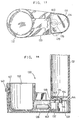
- a hair drier is provided with a body 11 and a stand 12 for retaining the drier body 11.
- the stand 12 is provided with an adjusting device 13 for adjusting the height of the drier body 11 when it is inserted therein, and a storage space 15 for a power cord 14.
- toilet sets of accessories may be contained in the space 15.
- the drier body 11 comprises an almost square pole handle 17 as a grip with the power cord 14 connected to the lower end and a changeover switch 16 disposed thereon, and a drier head 20 having a bracket 19 foldable and turnable round a boss 18 on an upper end of the handle 17.
- the drier head 20 further contains an electric heater and a blast fan.
- the stand 12 comprises a cylinder 21 for receiving the grip 17, a cylindrical container 22 with a diameter the same as or somewhat larger than that of the drier head 20, and a cylinder 23 for coupling the container 22 and the cylinder 21 horizontally together.
- the coupling cylinder 23, the container 22 and the cylinder 21 define a continuous notched grooved 24 for passage of the power cord therethrough.
- the space 15 is defined by the container 22 and the coupling cylinder 23.
- the end of the groove 24 on cylinder 21 is enlarged to form an opening 25 to expose the switch 16 on the grip 17.
- the cylinder 21 has an inner wall 26 of substantially trapezoidal cross-section.
- the height adjusting device 13 exploits this feature, and comprised a guide slot 27 for an adjusting knob 28 formed on a side wall 21a of the cylinder 21.
- the adjusting knob 28 is shiftable horizontally along the slot 27, and has a projection 29 extending inwardly therefrom.
- the projection 29 blocks the passage of the grip 17 into the cylinder 21 and supports the grip at an elevated position.
- the grip 17 is unimpeded, and can assume a lower position, as shown in Figure 1.
- the body and grip are removed from the stand, and the user holds the grip 17.
- the grip 17 remains in the cylinder 21 of the stand 12, and the drier head 20 swung around the boss 18 to expose the power cord 14.
- a supply plug 31 on the end of the power cord 14 is drawn out of the top of the container 22 to connect to a power supply.
- the power cord 14 can thus be withdrawn through the notched groove 24, enabling the grip 17 to be removed from the cylinder 21 of the stand 12, even when the plug 31 is connected.
- the changeover switch 16 When using the drier mounted on the stand, for example on a desk or table, the changeover switch 16 is exposed in the opening 25 on the cylinder 21, and is ready for ON/OFF operation in this position.
- the angle of the drier head 20 can be set arbitrarily by pivoting the drier head 20 round the boss 18.
- the grip 17 is folded to the drier head 20 as shown in Figure 1, and the adjusting knob 28 is set in the position shown in Figure 4.
- the drier head 20 will then cover the top of the container 22 with the power cord 14 contained therein, thus realizing a compact and tidy assembly.
- the grip will be loosely confined in the cylinder 21 which effectively locates the drier head on the container 22 and thereby prevents the drier body 11 from coming off the stand 12.
- the cylinder 21 can be used as a handle, and the drier can be carried very easily by inserting a hand in a space 33 formed between the container 22 and the cylinder 21.
- the grip 17 of the hair drier body 11 is lifted from the stand 12, and the adjusting knob 28 of the height adjusting device 13 shifted rightward to the position shown in Figure 3.
- the grip 17 is then returned to the cylinder 21, the bottom surface of the grip 17 comes in contact with the projection 29, and the grip 17 is supported on the projection 29.
- the height of the hair drier body 11 can be adjusted between two levels by the device 13, thereby accommodating different sitting heights.
- the changeover switch 16 has a sliding switch knob 16a formed integrally with a plate member 34 for sliding against an inner wall shell of the handle 17.
- the switch can be changed between OFF, COOL, WEAK, and STRONG positions by sliding the switch knob 16a vertically.
- an upper end 16c of the plate member 34 is extended almost as high as the centre of an upper end portion 35 of the grip 17.
- the upper end 16c of the plate member 34 is formed with a hook protrudes from a slit 36 provided on a side wall surface of the handle 17.
- Reference numeral 37 denotes a rib projecting from an inner wall of the bracket 19 in parallel with a boss 38, having an L-shaped section.
- the rib 37 is separated from the upper end 16c of the plate member 34.
- the switch knob 16a can then be operated to slide arbitrarily in the range STRONG to OFF while the drier is used.
- the rib 37 rotates with the hair drier head 20 and comes into contact with the upper end 16c of the plate member.
- the upper end 16c of the plate member is depressed, and when the hair drier head 20 is folded completely the switch knob 16a is shifted as STRONG ⁇ WEAK ⁇ COOL ⁇ OFF to the position shown in Figure 6, and thus the power is disconnected.
- the rib 37 is preset to shift the plate member 34 by a distance corresponding to the distance in which the switch knob 16a shifts from the position STRONG to OFF.
- the boss 38 is fitted in a through hole 39 of the handle 17 as shown in a main part sectional view of Figure 8.
- a boss 40 is then fitted likewise in the through hole 39, right and left side members 19a, 19b are paired up, and a bolt 41 locked at the boss 38 is mounted through the boss 40.
- a lead wire 42 connects the motor and the heater to the switch 16.
- FIG. 9 is a circuit diagram of the above-described embodiment, in which a switch 43 controls the operation of a motor 44 and a heater 46 through a diode 45, a thermostat 47, a temperature fuse 48, a dropper resistance 49, a diode 50, and a capacitor 51.
- This configuration is identical with an electric circuit of the prior art hair drier.
- FIG 10 is a sectional side view of the hair drier body.
- a heater 61, a motor 62, a blast fan 63 are disposed in that order from an intake side opening 60 in the hair drier head 20 to a discharge port 32.
- the heater 61 is for heating the air to be discharged, and is fixed spirally on a guide plate 64 provided on an inner wall of the hair drier head 20.
- the motor 62 is for driving the blast fan 63 and disposed almost at the centre of the heater 61.
- Reference numeral 65 denotes a collecting mechanism which will be described hereinlater. This arrangement of the heater 61 and the blast fan 63 is opposite to that of the prior art.
- Figure 11 represents the temperature distribution of the hot air coming out of the discharge port 32 in the drier illustrated
- Figure 12 represents a temperature distribution of the hot air coming out of the discharge port of a comparable prior art hair drier.
- the ordinate axis on the right side graph corresponds with a diameter of the discharge port 32 in the configuration of heater, motor and blast fan shown on the left, indicating a distribution of the hot air temperature.
- the hot air temperature is almost constant around 90°C, ensuring uniform temperature of the hot air to be obtained.
- hot air temperature changes from about 60°C to about 120°C between the central portion of the discharge port 72 and the outer peripheral zones as indicated by the right side graph, and thus it is understood that a uniform temperature of hot air is not obtainable.
- air is taken in from the intake side opening 60 simultaneously with rotation of the blast fan 63, and when the heater 61 is actuated, the air taken in through heat conduction is heated.
- the hot air is uneven in temperature at this point in time.
- the hot air is stirred to an even temperature when passing through the blast fan 63, and the hot air is thus uniform in temperature as it leaves the discharge port 32.
- a fin 66 for straightening the flow of a hot air and also for sending the hot air efficiently is provided between the blast fan 63 and the discharge port 32.
- the discharge port 32 is formed to have a large aperture of about 90 mm diameter so as to shorten the drying time, and accommodate large air flows therethrough.
- Reference 73 denotes an angle bar disposed on the inside of a discharge port frame 74, which is fixed on the frame 74 with a holding screw 75. Holes 76, 77 for rotatably supporting a shutter described hereinafter are provided on the angle bar 73.
- Reference numeral 78 denotes an angle bar fixed on the frame 74 at a position opposite to the angle bar 73, which is provided with holes 79, 80 as in the case of angle bar 73.
- References 81, 82 denote semicircular shutters working as blades provided like shelves within the hair drier body head 20 on the inside of the discharge port 32.
- the shutter 81 has two supporting points 83, 84 on one end portion, and the shutter 82 also has two supporting points 85, 86.
- the supporting points 83, 84 and 85, 86 function as the centres on which the shutters 81, 82 are fitted in the holes 76, 79 and the holes 77, 80 respectively.
- a tension coil spring 87 for energizing the shutter 81 in the direction indicated by arrow A and the shutter 82 in the direction indicated by arrow B is mounted on both end portions of the shutter 81 and the shutter 82.
- Reference 88 denotes a shutter shifting member movable along the angle bar 73, which retains the shutters 81, 82 horizontally (in the direction parallel with the blast) when it comes leftward of the supporting point 83, but allows the shutters 81, 82 to converge (in the direction condensing the blast) by virtue of the tensile force of the coil spring 87 when it comes rightward of the supporting point 83.
- the shutter shifting member 88 has a knob 30 formed integrally therewith, and the knob 30 projects from a slot 90 provided on the hair drier head 20.
- the shutters 81, 82 are shifted through the shutter shifting member 88 simultaneously with sliding the knob 30, thus changing angles of the shutters 81, 82. Whether the blast is sent out generally or intensively can thereby be selected.
- the knob 30 is held on the head 20 by projection 91.
- the collecting mechanism enables the air flow to be discharged generally or intensively simply by operating the knob 30. Accordingly, a separate collecting nozzle is not required. Because it is part of the drier head assembly, the collecting mechanism can be set more efficiently, and the drier as a whole is more compact because a space for storing a separate collecting nozzle is not needed.
- Figures 15 and 16 are side views showing the pivotal joint between the hair drier head 20, and the grip 17.
- the grip 17 is coupled to the drier head 20 via a bracket 19 and pivotal relative thereto about the bosses 38 and 40 (see Figure 8).
- a torsion spring 120 is laid between a handle side hole 121 provided near the through hole 39 of the handle 17 and a bracket side hole 122 provided on an inner wall portion of the bracket 19.
- a force in the direction indicated by arrow C is applied to the drier head 20 according to a reaction force of the torsion spring 120, which maintains the angle between the hair drier head 20 and the handle 17 at around 90°.
- the torsion spring 120 bends through an equilibrium position to one where a force in the direction indicated by arrow D is applied to the hair drier head 20.
- the hair drier head 20 and the handle 17 are kept folded and so retained in the compact orientation shown in Figure 1.
- the hair drier head 20 can be located in either operative or folded positions relative to the grip, and so retained without additional fittings being needed.
- the stand 12 may omit the coupling cylinder 23 such that the cylinder 21 and the cylindrical container 22 are unified.
- the height adjusting device 13 may be realized from constructing the cylinder 21 as an expansive fixed cylinder or an expansive moving cylinder.
- Figures 17 and 18 show how this can be done.
- a stand 130 comprises a cylinder 131 for containing the grip 17, and a stand base 133 having a container 132.
- the cylinder 131 is mounted on the base 133 by means of a shaft 134 depending from its base, which has a slide groove 135 formed therein for receiving a slide post 140.
- the stand base 133 has a shaft support 136 for supporting the shaft 134 on the upper surface and is fitted with an electric motor 137 and a battery 138 therefor.
- the motor 137 has a reduction unit and rotates an external shaft thereof slowly.
- a disc cam 139 is fixed on the external shaft of the motor 137, and the slide post 140 is formed integrally on an upper surface of the cam.
- a projection 144 keeps the cylinder 131 vertical.
- the switch knob 142 When the switch knob 142 is turned to an ON position, the motor 137 rotates, and the cam shaft 140 turns. When the cam shaft 140 turns, the slide groove 135 makes pendulous movements (arrows E, F), and the cylinder 131 oscillates about the shaft 134. In this way, a user may obtain an air flow from the drier head at different angles without moving his head. While an external power source might be used instead of the battery 138, this would require an additional power lead. Accordingly, the use of a battery is preferred.
Landscapes
- Cleaning And Drying Hair (AREA)
Claims (2)
- Sèche-cheveux ayant un corps de séche-cheveux (11) et une poignée (17), dans lequel le corps de séche-cheveux comprend un élément cylindrique (20) avec une ouverture d'aspiration (60) et une ouverture de décharge (32), un mécanisme de chauffage (61) et un ventilateur de soufflage (63) qui sont disposés dans cet ordre dans l'élément cylindrique de l'ouverture d'aspiration à l'ouverture de décharge,
caractérisé en ce que
le corps de séche-cheveux (11) inclut une pluralité de lames planes (81, 82, 104, 105) prévues sur le côté de décharge du ventilateur (63), les lames étant articulées autour d'axes parallèles traversant le chemin de flux de l'air le long de, et à travers, l'élément cylindrique (20), chaque axe se trouvant dans le plan de la lame respective; et un mécanisme d'actionnement de lames pour déplacer les lames entre une orientation parallèle et une orientation convergente, afin de permettre ainsi à l'air déchargée par l'ouverture (32) d'être intensifié, et chaque extrémité d'un ressort de bobine de tension (87) étant montée sur une partie d'extrémité respective de chaque lame d'une paire de lames (81, 82) afin d'incliner les lames vers l'orientation convergente. - Sèche-cheveux selon la revendication 1, dans lequel au moins une ailette (66) pour redresser le flux d'air est prévue entre le ventilateur de soufflage (63) et les lames planes (81, 82, 104, 105).
Applications Claiming Priority (9)
| Application Number | Priority Date | Filing Date | Title |
|---|---|---|---|
| JP179351/87 | 1987-11-24 | ||
| JP1987179351U JPH068802Y2 (ja) | 1987-11-24 | 1987-11-24 | 毛髪乾燥機 |
| JP181235/87 | 1987-11-27 | ||
| JP181236/87 | 1987-11-27 | ||
| JP181234/87 | 1987-11-27 | ||
| JP18123687U JPH0186901U (fr) | 1987-11-27 | 1987-11-27 | |
| JP18123587U JPH0186902U (fr) | 1987-11-27 | 1987-11-27 | |
| JP1987181234U JPH061Y2 (ja) | 1987-11-27 | 1987-11-27 | ヘアドライヤー |
| EP88306407A EP0318133B1 (fr) | 1987-11-24 | 1988-07-13 | Sèche-cheveux |
Related Parent Applications (1)
| Application Number | Title | Priority Date | Filing Date |
|---|---|---|---|
| EP88306407.3 Division | 1988-07-13 |
Publications (3)
| Publication Number | Publication Date |
|---|---|
| EP0459528A2 EP0459528A2 (fr) | 1991-12-04 |
| EP0459528A3 EP0459528A3 (en) | 1992-01-29 |
| EP0459528B1 true EP0459528B1 (fr) | 1996-04-17 |
Family
ID=27474885
Family Applications (2)
| Application Number | Title | Priority Date | Filing Date |
|---|---|---|---|
| EP91111014A Expired - Lifetime EP0459528B1 (fr) | 1987-11-24 | 1988-07-13 | Sèche-cheveux |
| EP88306407A Expired - Lifetime EP0318133B1 (fr) | 1987-11-24 | 1988-07-13 | Sèche-cheveux |
Family Applications After (1)
| Application Number | Title | Priority Date | Filing Date |
|---|---|---|---|
| EP88306407A Expired - Lifetime EP0318133B1 (fr) | 1987-11-24 | 1988-07-13 | Sèche-cheveux |
Country Status (7)
| Country | Link |
|---|---|
| US (2) | US4904847A (fr) |
| EP (2) | EP0459528B1 (fr) |
| KR (1) | KR910000039B1 (fr) |
| AU (2) | AU613052B2 (fr) |
| CA (1) | CA1306105C (fr) |
| DE (2) | DE3874687T2 (fr) |
| HK (1) | HK127493A (fr) |
Families Citing this family (51)
| Publication number | Priority date | Publication date | Assignee | Title |
|---|---|---|---|---|
| USD322742S (en) | 1988-12-23 | 1991-12-31 | Black & Decker, Inc. | Hot air blower |
| USD343698S (en) | 1990-11-26 | 1994-01-25 | Carmen Limited | Hairdryer |
| US5275339A (en) * | 1992-12-10 | 1994-01-04 | Andis Company | Diffuser for hair dryer |
| US5727331A (en) * | 1996-06-27 | 1998-03-17 | Windmere Corporation | Dual switch electric hair dryer |
| USD398717S (en) | 1996-09-17 | 1998-09-22 | Braun Aktiengesellschaft | Hair dryer |
| US5834738A (en) * | 1997-01-16 | 1998-11-10 | Wilson; Michael | Heated golf bag apparatus |
| USD398073S (en) | 1997-02-12 | 1998-09-08 | U.S. Philips Corporation | Hair dryer with temperature sensor |
| USD415854S (en) * | 1998-08-10 | 1999-10-26 | The Gary L. Marcus Company, Inc. | Hair dryer stand |
| USD436690S1 (en) | 1999-05-04 | 2001-01-23 | Hamilton Beach/Proctor-Silex, Inc. | Hair dryer |
| US6907678B2 (en) | 1999-11-08 | 2005-06-21 | Hamilton Beach/Proctor-Silex, Inc. | Portable electric hair dryer and mount therefor |
| US6281482B1 (en) * | 2000-07-13 | 2001-08-28 | Defond Manufacturing Limited | Electrical switch |
| FR2817450B1 (fr) * | 2000-12-06 | 2003-02-14 | Seb Sa | Seche-cheveux a dispositif de variation de la section de sortie du flux d'air |
| CN2571239Y (zh) * | 2001-10-15 | 2003-09-10 | 公主环球有限公司 | 可站立式吹风机 |
| USD467035S1 (en) | 2002-01-10 | 2002-12-10 | Conair Cip, Inc. | Attachment for a hair dryer |
| US6739071B2 (en) * | 2002-03-01 | 2004-05-25 | Andis Company | Combined diffuser and concentrator for a hair dryer |
| EP1498165B1 (fr) * | 2002-04-23 | 2008-12-17 | CCP Co., Ltd. | Dispositif de commande en forme de poignee de pistolet |
| AU2003245168A1 (en) * | 2002-07-16 | 2004-02-02 | Young Ho Kwon | Hair dryer |
| US20040209514A1 (en) * | 2002-08-14 | 2004-10-21 | Marshall Yoe Han Leng | Personal care device support |
| US6691429B1 (en) * | 2002-11-14 | 2004-02-17 | Conair Corporation | Hair dryer with stand |
| US20040168337A1 (en) * | 2002-12-12 | 2004-09-02 | Caitlyn Curtin | Hands-free hair and body dryer that allows a wide range of motion |
| DE10336874A1 (de) * | 2003-08-11 | 2005-03-10 | Hilti Ag | Griffanordnung |
| US6966125B2 (en) * | 2003-09-18 | 2005-11-22 | Shoot The Moon Products Ii, Llc | Automatic air movement for hair dryers |
| US6925729B2 (en) * | 2003-10-29 | 2005-08-09 | Hamilton Beach/Proctor-Silex, Inc. | Hair dryer and mounting assembly |
| US6889445B1 (en) * | 2004-01-06 | 2005-05-10 | Sunbeam Products, Inc. | Multi-wattage blow dryer with user inaccessible power selector |
| USD516883S1 (en) | 2004-08-24 | 2006-03-14 | One World Technologies Limited | Heat gun |
| DE102007035245A1 (de) * | 2007-07-27 | 2009-01-29 | Braun Gmbh | Haarpflegegerät |
| DE102007060057A1 (de) * | 2007-12-13 | 2009-06-18 | Robert Bosch Gmbh | Handwerkzeugmaschine |
| BRPI0802885B1 (pt) * | 2008-07-25 | 2016-07-19 | Otalicio Pacheco Da Cunha | secador de grãos de alta performance |
| WO2010036733A1 (fr) * | 2008-09-23 | 2010-04-01 | Larada Sciences Inc. | Applicateurs de flux d’air et procédés de traitement apparentés |
| DE102009026829A1 (de) * | 2009-06-08 | 2010-12-09 | BSH Bosch und Siemens Hausgeräte GmbH | Haarpflegegerät mit Einstellmitteln |
| US8272142B2 (en) * | 2009-10-02 | 2012-09-25 | Vexpro, Llc | Hair dryer |
| US8555999B2 (en) * | 2010-04-30 | 2013-10-15 | Black & Decker Inc. | Twist-handled power tool with locking system |
| US9266230B2 (en) * | 2010-01-07 | 2016-02-23 | Black & Decker Inc. | Twist-handled power tool with locking system |
| US20120000085A1 (en) * | 2010-03-04 | 2012-01-05 | Clifford Wright | Upright hair dryer |
| US8707577B2 (en) * | 2010-11-19 | 2014-04-29 | Gary Brian Lee | Adjustable hair dryer |
| US8813384B2 (en) | 2011-07-07 | 2014-08-26 | Paradigm Style, Llc. | Hair dryer with dual axis rotatable handle |
| CN202233649U (zh) * | 2011-09-16 | 2012-05-30 | 尤汉贤 | 一种吹风机 |
| US8857447B2 (en) * | 2012-11-28 | 2014-10-14 | Conair Corporation | Hair treatment apparatus with cover for control elements |
| DE102014004602A1 (de) | 2014-03-27 | 2015-10-01 | Technische Universität Ilmenau | Vorrichtung und Verfahren zur Aufbereitung eines Luftstroms |
| CN204397850U (zh) * | 2015-01-14 | 2015-06-17 | 浙江普莱得电器有限公司 | 一种方便切换的多功能工具 |
| DE102015121891A1 (de) * | 2015-12-15 | 2017-06-22 | Wagner Spraytech (UK) Ltd. | System umfassend ein Heißlufthandgerät und einen Transportkoffer für das Heißlufthandgerät, Transportkoffer sowie Verfahren zum Betrieb eines Heißlufthandgeräts |
| USD837215S1 (en) * | 2016-08-01 | 2019-01-01 | Hand Held Products, Inc. | Optical scanner |
| US10779625B2 (en) * | 2018-07-09 | 2020-09-22 | Christine Thein | Battery powered collapsible blow-dryer |
| EP4085790B1 (fr) | 2018-09-19 | 2024-01-10 | LG Electronics Inc. | Support pour sèche-cheveux |
| DE102019100850A1 (de) * | 2019-01-14 | 2020-07-16 | Steinel Gmbh | Heißluftgebläse und Verfahren zum Betreiben desselben |
| US11076672B2 (en) | 2019-12-09 | 2021-08-03 | Conair Corporation | Hair dryer with side switches |
| US12446547B2 (en) | 2021-01-08 | 2025-10-21 | Alyssa Lynn Fox | System and method for eradicating ectoparasites |
| US12501982B2 (en) | 2021-11-12 | 2025-12-23 | Sharkninja Operating Llc | Hair care appliance |
| US11653737B1 (en) | 2021-11-12 | 2023-05-23 | Sharkninja Operating Llc | Hair care appliance |
| US12225995B2 (en) | 2021-11-12 | 2025-02-18 | Sharkninja Operating Llc | Hair care appliance |
| CN117168116A (zh) * | 2023-09-19 | 2023-12-05 | 江西百神药业股份有限公司 | 一种八珍益母丸的干燥装置 |
Family Cites Families (26)
| Publication number | Priority date | Publication date | Assignee | Title |
|---|---|---|---|---|
| US1352876A (en) * | 1919-04-01 | 1920-09-14 | Barbers Electric Specialty Com | Electric hair-drying device |
| US1809458A (en) * | 1929-09-20 | 1931-06-09 | Wahl Clipper Corp | Hair drier |
| US2036597A (en) * | 1935-09-05 | 1936-04-07 | Meyrowitz Emanuel | Combined fan and heater |
| GB647291A (en) * | 1948-01-14 | 1950-12-13 | Frederick George Cooke | Improvements relating to electric hair driers |
| FR1336066A (fr) * | 1960-04-15 | 1963-08-30 | Appareil de petites dimensions, pour production d'un jet d'air, commandé par moteur électrique, et destiné en particulier aux sèche-cheveux | |
| US3362086A (en) * | 1966-05-31 | 1968-01-09 | Gen Electric | Hair dryer with selective telescopic adjusting means |
| FR1546750A (fr) * | 1967-10-11 | 1968-11-22 | L T Piver S A | Sèche-cheveux à température et à débit d'air réglables |
| LU59050A1 (fr) * | 1969-07-08 | 1970-07-09 | ||
| US3775590A (en) * | 1971-10-27 | 1973-11-27 | Steiner W | Portable space heater |
| US3846047A (en) * | 1972-02-28 | 1974-11-05 | Matsushita Electric Works Ltd | Foldable hair dryer |
| FR2242947B1 (fr) * | 1973-09-11 | 1978-07-13 | Sfem | |
| FR2250270A7 (en) * | 1973-11-06 | 1975-05-30 | Gagne Alain | Portable hair-drier support - has mounting surface joined by uprights to member supporting or suspending drier |
| CH574721A5 (fr) * | 1974-03-01 | 1976-04-30 | Rotel Ag | |
| US4053732A (en) * | 1975-11-05 | 1977-10-11 | Carter Frank H | Portable electric room air heater |
| US4003388A (en) * | 1976-04-01 | 1977-01-18 | General Electric Company | Hair dryer variable control |
| DE2644017A1 (de) * | 1976-09-30 | 1978-04-06 | Spemot Ag Dulliken | Staender fuer haartrockner |
| JPS601369B2 (ja) * | 1977-09-06 | 1985-01-14 | 堺化学工業株式会社 | 分離方法 |
| JPS553926A (en) * | 1978-06-26 | 1980-01-12 | Asahi Chemical Ind | Simple preparation of board for outer wall |
| US4232454A (en) * | 1979-06-14 | 1980-11-11 | Clairol Incorporated | Variable airflow hair treatment device |
| US4278223A (en) * | 1979-08-10 | 1981-07-14 | Fauteux Denis J | Self supporting stand for hand held hair drier |
| US4309595A (en) * | 1980-07-14 | 1982-01-05 | Sunbeam Corporation | Hair dryer |
| EP0056188A3 (fr) * | 1981-01-09 | 1984-05-02 | Hendon Precision Engineering Company Limited | Combinaison séche-cheveux-support |
| DE8132446U1 (de) * | 1981-11-06 | 1982-03-11 | Braun Ag, 6000 Frankfurt | Haartrockner |
| BR6200942U (pt) * | 1982-07-19 | 1984-02-28 | Walita Eletro Domestico Ltda | Secador de cabelos |
| DE3245655A1 (de) * | 1982-09-01 | 1984-06-14 | Johann Josef 8918 Diessen Kerschgens | Uv-bestrahlungsvorrichtung vorzugsweise als vorsatzeinrichtung fuer einen foen |
| US4653201A (en) * | 1986-01-09 | 1987-03-31 | Kohler Co. | Combined mirror and dryer air outlet assembly |
-
1988
- 1988-06-30 AU AU18558/88A patent/AU613052B2/en not_active Ceased
- 1988-07-05 CA CA000571192A patent/CA1306105C/fr not_active Expired - Lifetime
- 1988-07-13 EP EP91111014A patent/EP0459528B1/fr not_active Expired - Lifetime
- 1988-07-13 DE DE8888306407T patent/DE3874687T2/de not_active Expired - Fee Related
- 1988-07-13 DE DE3855222T patent/DE3855222T2/de not_active Expired - Fee Related
- 1988-07-13 EP EP88306407A patent/EP0318133B1/fr not_active Expired - Lifetime
- 1988-07-30 KR KR1019880009725A patent/KR910000039B1/ko not_active Expired
- 1988-08-05 US US07/228,572 patent/US4904847A/en not_active Expired - Fee Related
-
1989
- 1989-10-17 US US07/423,337 patent/US4977306A/en not_active Expired - Fee Related
-
1991
- 1991-04-18 AU AU75254/91A patent/AU637688B2/en not_active Ceased
-
1993
- 1993-11-18 HK HK1274/93A patent/HK127493A/en not_active IP Right Cessation
Also Published As
| Publication number | Publication date |
|---|---|
| DE3855222T2 (de) | 1996-10-02 |
| HK127493A (en) | 1993-11-26 |
| EP0318133B1 (fr) | 1992-09-16 |
| DE3874687D1 (de) | 1992-10-22 |
| EP0459528A3 (en) | 1992-01-29 |
| AU1855888A (en) | 1989-05-25 |
| DE3855222D1 (de) | 1996-05-23 |
| CA1306105C (fr) | 1992-08-11 |
| US4904847A (en) | 1990-02-27 |
| EP0459528A2 (fr) | 1991-12-04 |
| US4977306A (en) | 1990-12-11 |
| AU7525491A (en) | 1991-07-18 |
| AU613052B2 (en) | 1991-07-25 |
| EP0318133A1 (fr) | 1989-05-31 |
| KR910000039B1 (ko) | 1991-01-19 |
| DE3874687T2 (de) | 1993-03-25 |
| AU637688B2 (en) | 1993-06-03 |
| KR890007696A (ko) | 1989-07-05 |
Similar Documents
| Publication | Publication Date | Title |
|---|---|---|
| EP0318133B1 (fr) | Sèche-cheveux | |
| US4219178A (en) | Storage or holder device for electrical appliance | |
| KR101002139B1 (ko) | 전기솥 | |
| US4232454A (en) | Variable airflow hair treatment device | |
| US4688340A (en) | Travel steam and dry iron | |
| US4198558A (en) | Hair dryer | |
| CA1292614C (fr) | Sechoir pour cheveux | |
| US5390433A (en) | Pressing iron with cord swivel cord guard and lobed heel | |
| US4198556A (en) | Hair dryer | |
| KR960014567B1 (ko) | 헤어 드라이어 후드 | |
| JP7095164B2 (ja) | スチーマー | |
| JP7476400B2 (ja) | ドライヤー | |
| US20240344263A1 (en) | Clothing processing apparatus | |
| JP2020054575A5 (fr) | ||
| KR20220112886A (ko) | 드라이기 거치대를 포함하는 드라이기 세트 | |
| JP7019079B2 (ja) | スチーマー | |
| JPS5943017Y2 (ja) | 電気アイロン付ヘヤ−ドライヤ兼電気かみそり | |
| CN223730918U (zh) | 一种可转动的电吹风 | |
| JPH07221A (ja) | スタンド型ヘアドライヤー | |
| CA1061391A (fr) | Appareil de chauffage a circulation forcee, sous enveloppe facile d'acces | |
| JP7406905B2 (ja) | ドライヤー | |
| CA2165042A1 (fr) | Chaufferette orientable | |
| JP3973375B2 (ja) | コードリール付アイロン | |
| JPS6022959Y2 (ja) | ドライヤ付電気アイロン | |
| JPH068802Y2 (ja) | 毛髪乾燥機 |
Legal Events
| Date | Code | Title | Description |
|---|---|---|---|
| PUAI | Public reference made under article 153(3) epc to a published international application that has entered the european phase |
Free format text: ORIGINAL CODE: 0009012 |
|
| 17P | Request for examination filed |
Effective date: 19910703 |
|
| AC | Divisional application: reference to earlier application |
Ref document number: 318133 Country of ref document: EP |
|
| AK | Designated contracting states |
Kind code of ref document: A2 Designated state(s): DE FR GB |
|
| PUAL | Search report despatched |
Free format text: ORIGINAL CODE: 0009013 |
|
| AK | Designated contracting states |
Kind code of ref document: A3 Designated state(s): DE FR GB |
|
| 17Q | First examination report despatched |
Effective date: 19940303 |
|
| GRAH | Despatch of communication of intention to grant a patent |
Free format text: ORIGINAL CODE: EPIDOS IGRA |
|
| GRAA | (expected) grant |
Free format text: ORIGINAL CODE: 0009210 |
|
| AC | Divisional application: reference to earlier application |
Ref document number: 318133 Country of ref document: EP |
|
| AK | Designated contracting states |
Kind code of ref document: B1 Designated state(s): DE FR GB |
|
| REF | Corresponds to: |
Ref document number: 3855222 Country of ref document: DE Date of ref document: 19960523 |
|
| ET | Fr: translation filed | ||
| PLBE | No opposition filed within time limit |
Free format text: ORIGINAL CODE: 0009261 |
|
| STAA | Information on the status of an ep patent application or granted ep patent |
Free format text: STATUS: NO OPPOSITION FILED WITHIN TIME LIMIT |
|
| 26N | No opposition filed | ||
| PGFP | Annual fee paid to national office [announced via postgrant information from national office to epo] |
Ref country code: GB Payment date: 19970704 Year of fee payment: 10 |
|
| PGFP | Annual fee paid to national office [announced via postgrant information from national office to epo] |
Ref country code: FR Payment date: 19970723 Year of fee payment: 10 |
|
| PGFP | Annual fee paid to national office [announced via postgrant information from national office to epo] |
Ref country code: DE Payment date: 19970730 Year of fee payment: 10 |
|
| PG25 | Lapsed in a contracting state [announced via postgrant information from national office to epo] |
Ref country code: GB Free format text: LAPSE BECAUSE OF NON-PAYMENT OF DUE FEES Effective date: 19980713 |
|
| GBPC | Gb: european patent ceased through non-payment of renewal fee |
Effective date: 19980713 |
|
| PG25 | Lapsed in a contracting state [announced via postgrant information from national office to epo] |
Ref country code: FR Free format text: LAPSE BECAUSE OF NON-PAYMENT OF DUE FEES Effective date: 19990331 |
|
| PG25 | Lapsed in a contracting state [announced via postgrant information from national office to epo] |
Ref country code: DE Free format text: LAPSE BECAUSE OF NON-PAYMENT OF DUE FEES Effective date: 19990501 |
|
| REG | Reference to a national code |
Ref country code: FR Ref legal event code: ST |