EP0459583A1 - Ultraschallbildgerät mit adaptiver Phasenaberrationskorrektur - Google Patents
Ultraschallbildgerät mit adaptiver Phasenaberrationskorrektur Download PDFInfo
- Publication number
- EP0459583A1 EP0459583A1 EP91201273A EP91201273A EP0459583A1 EP 0459583 A1 EP0459583 A1 EP 0459583A1 EP 91201273 A EP91201273 A EP 91201273A EP 91201273 A EP91201273 A EP 91201273A EP 0459583 A1 EP0459583 A1 EP 0459583A1
- Authority
- EP
- European Patent Office
- Prior art keywords
- reception
- focusing
- delays
- transducer elements
- correction
- Prior art date
- Legal status (The legal status is an assumption and is not a legal conclusion. Google has not performed a legal analysis and makes no representation as to the accuracy of the status listed.)
- Granted
Links
- 238000012937 correction Methods 0.000 title claims abstract description 62
- 230000003044 adaptive effect Effects 0.000 title description 2
- 230000004075 alteration Effects 0.000 title description 2
- 230000001934 delay Effects 0.000 claims abstract description 63
- 238000012545 processing Methods 0.000 claims abstract description 50
- 238000000034 method Methods 0.000 claims abstract description 27
- 238000002604 ultrasonography Methods 0.000 claims description 42
- 230000005540 biological transmission Effects 0.000 claims description 32
- 238000012986 modification Methods 0.000 claims description 7
- 230000004048 modification Effects 0.000 claims description 7
- 238000006073 displacement reaction Methods 0.000 claims description 3
- 238000012360 testing method Methods 0.000 abstract description 3
- 230000002596 correlated effect Effects 0.000 abstract 1
- 230000000875 corresponding effect Effects 0.000 abstract 1
- 239000000523 sample Substances 0.000 description 15
- 230000006870 function Effects 0.000 description 13
- 238000002592 echocardiography Methods 0.000 description 8
- 230000005284 excitation Effects 0.000 description 7
- 238000004364 calculation method Methods 0.000 description 6
- 238000011144 upstream manufacturing Methods 0.000 description 5
- 230000015572 biosynthetic process Effects 0.000 description 4
- 238000006243 chemical reaction Methods 0.000 description 4
- 230000003111 delayed effect Effects 0.000 description 4
- 238000001514 detection method Methods 0.000 description 4
- 230000008569 process Effects 0.000 description 4
- 238000003491 array Methods 0.000 description 3
- 230000008901 benefit Effects 0.000 description 3
- 230000000737 periodic effect Effects 0.000 description 3
- 230000003213 activating effect Effects 0.000 description 2
- 230000004913 activation Effects 0.000 description 2
- 230000000694 effects Effects 0.000 description 2
- 230000036962 time dependent Effects 0.000 description 2
- 238000012800 visualization Methods 0.000 description 2
- 230000015556 catabolic process Effects 0.000 description 1
- 238000010276 construction Methods 0.000 description 1
- 238000006731 degradation reaction Methods 0.000 description 1
- 238000012217 deletion Methods 0.000 description 1
- 230000037430 deletion Effects 0.000 description 1
- 238000011161 development Methods 0.000 description 1
- 229940082150 encore Drugs 0.000 description 1
- 239000000284 extract Substances 0.000 description 1
- 238000001914 filtration Methods 0.000 description 1
- 230000006872 improvement Effects 0.000 description 1
- 238000012804 iterative process Methods 0.000 description 1
- 238000012417 linear regression Methods 0.000 description 1
- 150000002632 lipids Chemical class 0.000 description 1
- 210000004185 liver Anatomy 0.000 description 1
- 239000000463 material Substances 0.000 description 1
- 239000011159 matrix material Substances 0.000 description 1
- 238000005259 measurement Methods 0.000 description 1
- 238000009659 non-destructive testing Methods 0.000 description 1
- 230000005855 radiation Effects 0.000 description 1
- 238000012163 sequencing technique Methods 0.000 description 1
- 230000002123 temporal effect Effects 0.000 description 1
Images


Classifications
-
- G—PHYSICS
- G01—MEASURING; TESTING
- G01S—RADIO DIRECTION-FINDING; RADIO NAVIGATION; DETERMINING DISTANCE OR VELOCITY BY USE OF RADIO WAVES; LOCATING OR PRESENCE-DETECTING BY USE OF THE REFLECTION OR RERADIATION OF RADIO WAVES; ANALOGOUS ARRANGEMENTS USING OTHER WAVES
- G01S7/00—Details of systems according to groups G01S13/00, G01S15/00, G01S17/00
- G01S7/52—Details of systems according to groups G01S13/00, G01S15/00, G01S17/00 of systems according to group G01S15/00
- G01S7/52017—Details of systems according to groups G01S13/00, G01S15/00, G01S17/00 of systems according to group G01S15/00 particularly adapted to short-range imaging
- G01S7/52046—Techniques for image enhancement involving transmitter or receiver
- G01S7/52049—Techniques for image enhancement involving transmitter or receiver using correction of medium-induced phase aberration
Definitions
- Such a method and apparatus can be used in particular in the medical field, or else for the non-destructive testing of all kinds of materials, without such applications being, of course, limiting.
- An ultrasound system is a device for examining environments using ultrasound radiation as a source of information.
- Such an apparatus implements, for its operation, a step of transmitting, by periodic shots, ultrasonic signals towards the explored medium as well as a step of receiving and processing the echoes returned by the obstacles encountered in the explored medium.
- the two stages are carried out with the same ultrasonic probe in contact with the medium.
- This probe is a structure generally made up of a whole network of ultrasonic transducers.
- the medium is selectively explored along a line.
- the image of this explored line is formed by taking into account the time of flight in the environment and the amplitude of the echoes from the various obstacles encountered on the line.
- the image of a section plane is produced by scanning this line.
- a commonly used focusing technique consists in using a linear array of transducers and in defining on emission a focused incident beam using a law of delays imposed on the excitation pulses of the transducers.
- the focusing is then carried out in a similar manner, by appropriately delaying the signals received by each of the transducers of the network, before their summation and the subsequent processing.
- This processing of the signals on reception which results in having a large amplitude signal for the echoes coming from the focal point (this point is located on the explored line) and weak signals for all the other echoes, is usually called track formation.
- linear arrays of transducer elements provides the possibility not only to focus, but also to carry out the scanning necessary for the formation of the two-dimensional image.
- This scanning can be carried out in at least three different ways, described with reference to FIG. 1, which shows different types of probes with, each time, representation of the acoustic openings A used, of the axes B of the beams formed, and of the limits D of the field explored.
- the first solution the simplest, consists (see Figure 1a) in using a network of a hundred (or more) transducers (128 are commonly used).
- a transmission / reception aperture of given size is then defined (16 to 64 elements typically), which focuses on transmission and reception along an axis perpendicular to the network.
- the scanning is obtained by moving the aperture by analog multiplexing. Two successive openings thus defined have an intersection which is the entire opening except one or a few transducer elements. This operating mode makes it possible to obtain images of an area of the medium contained in the geometric shadow of the probe.
- the other mode of use is mainly used to obtain images of areas larger than the imprint of the probe on the medium.
- the laws of delay in transmission and in reception are calculated so that the ultrasonic beam can have any angle relative to the axis of the probe.
- the image is obtained by scanning an angular sector (most often from -45 to +45 degrees).
- Such systems called in English "phased arrays", allow in particular, in the case of applications in the medical field, to produce images of the heart through the acoustic window formed by one of the intervals between the ribs.
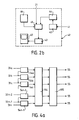
- the ultrasound system thus represented firstly comprises a network of m ultrasonic transducers 10a to 10m connected to an analog switch 15 which makes it possible to define the opening.
- the other end of this switcher 15 is connected on the one hand to a transmission stage 20 and on the other hand to a reception and processing stage 30.
- the sequencer circuit 21 delivers not only the synchronization pulses of the ultrasonic shots, but also the control signals of a circuit 25 for focusing control on transmission.
- This circuit 25 contains in memory the sequence of emission delay laws for each transducer, this sequence being intended to ensure the configuration of the delay lines 23a to 23n of the focusing circuit 23 according to a predefined law for each shot.
- the gain compensation circuit 32 essentially comprises n amplifiers 32a to 32n with variable gain as a function of time, controlled by a control circuit 35 which itself receives synchronization pulses from the sequencer circuit 21.
- the circuit 33 of focusing at reception is connected to a memory 34 containing in memory, for each channel, all of the delay laws for each focusing zone and for each line of the image, this memory 34 being itself, too, controlled by the sequencer circuit 21.
- Said focusing and summing functions can moreover be performed differently from what has already been described, by proposing this time, for their implementation, as also shown in FIG. 2c, a switch 36 and a delay line 37 unique.
- This switcher 36 controlled by the sequencer 34 provided as above at the output of the circuit 21, has as many inputs as there are transducers in the opening and as many outputs as possible delays. These outputs are connected to the various input points of the delay line 37.
- the switch 36 receives the output signals from the gain compensation circuit 321, converts them into current and then directs each signal thus formed to the output which corresponds to the desired delay. The summation is carried out by the natural addition of the currents entering the delay line 37.
- the operating principle of current ultrasound systems is generally based on the assumption of a constant ultrasonic speed in the tissues explored, in particular to allow the calculation of the different focusing delays and the possible angulation of the beams and to allow conversion into information. depth of information related to echo flight times.
- the speed of propagation of ultrasound has for example an average value in the liver 1540 m / s, while, in lipid tissues, it is worth approximately 1300 m / s. This results in both emission in reception, especially a defocusing effect of the ultrasonic beams, which results in a loss of resolution and of image contrast all the more important when larger focusing apertures and probes of higher frequency are used.
- the influence of the frequency on the degradation thus observed can be understood by recalling the need to maintain an accuracy on the delays of about an eighth of wavelength, which corresponds to an accuracy all the better as the frequency is higher, while the influence of the size of the opening can be explained by finding that, the larger the opening, the higher the probability of encountering zones of different speed of sound.
- the object of the invention is to propose an improved method for correcting the effects of inhomogeneities of the ultrasonic speed.
- the invention relates for this purpose to a method as defined in the preamble to the description and remarkable in that the reception and processing step also comprises a step of correcting, as a function of said (n-1) determined values, the delays focus on reception, during the same shot.
- This method has the advantage of authorizing a real-time operation of the corrections made in the ultrasound system.
- the reception and processing step comprises, prior to the correction of the focusing delays on transmission, an operation of moving the opening of a number p of transducer elements equal to 1 or small compared to the number n, said correction being then applied only to (np) transducer elements common to two successive openings.
- the displacement of the opening is obtained not by modifying the selection of the determined number n of transducer elements, but by modification of the delay law applied to the m transducers, and the correction step then concerns all of these m transducers.
- the process then allows either to make two shots (or more) for each emission focal point, or use the corrections in cascade from one depth to another, then from one line to another, or again to use for each depth the delays determined for the previous line at the same depth.
- the reception and processing step comprises, prior to the correction of the focusing delays, an operation of detecting an anechogenic zone in the medium explored and / or of detecting a linear component in the delays of focus.
- aberrations are corrected on the basis of signals from an environment considered to be relatively uniform, that is to say without a target clearly brighter than the rest of the environment explored or , on the contrary, without an anechoic zone.
- the tissues explored can sometimes be highly non-uniform, and the detection of these irregularities is very useful.
- the object of the invention is also to propose an apparatus for implementing the method which has just been described.
- the invention relates for this purpose to an apparatus as defined in the preamble to the description and remarkable in that the reception and processing stage also comprises means for correcting, as a function of the (n-1) determined values, focusing delays on reception, during the same shot, the means for correcting focusing delays preferably comprising a sequencer provided for defining in each channel the appropriate focusing delay.
- a scanning control stage for moving the ultrasonic opening on the array of transducer elements
- said control stage comprises means for moving said opening of a number p of transducer elements equal to 1 or low compared to the number n, each correction of the focusing delays on transmission being applied only after said shift and on only the (np) transducer elements common to two successive openings.
- said control stage comprises means for moving the opening by modification of the delay law applied to the transducer elements.
- said apparatus can also include means for interrupting correction as a function of a predetermined criterion.
- an examination of environments by ultrasound echography comprises a step of emission by periodic shots carried out from a network of m transducer elements of which n are selected to constitute the ultrasonic opening (n is generally less than m) .
- This step of sending n ultrasonic signals to the medium to be explored is followed by a step of receiving and processing the ultrasound signals returned to said n transducers by the obstacles encountered in this medium.
- a focusing operation is provided by applying an appropriate delay law respectively in the n transmission channels and in the n reception channels associated with the n transducer elements constituting the ultrasonic opening.
- the reception and processing step also comprises, following step (a), a correction step on reception during the same shot, this correction of the focusing delays being always carried out from (n-1) determined correction values.
- a variant of the method according to the invention consists in providing, before the step of correcting the focusing delays on transmission, an operation for moving the opening.
- this displacement is carried out by shifting a number p of transducer elements equal to 1 or small compared to the number n (for example not exceeding 1/10 th of this value), said correction is only applied to ( np) transducer elements common to two successive openings.
- the opening can be moved by modification of the law of delays applied to the m transducer elements, and the correction is applied to these m elements.
- the reception and processing step in which, as we have just indicated, an iterative correction has therefore been provided either for transmission, or for transmission and reception, can also include, according to the invention, a timeout, in order to interrupt the iterative correction process as soon as it is estimated, according to a predetermined criterion, that this correction is effective and sufficient.
- the interruption criterion is for example the control of the execution of a predetermined number of shots, or else is based on an energy calculation of the ultrasound line.
- Another variant also consists in providing, before the correction of the focusing delays, a step of detecting an anechoic zone in the medium explored and / or of detecting a linear component in the focusing delays.
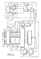
- FIG. 3 An exemplary embodiment of an ultrasound system ultrasonic is shown in FIG. 3.
- This device firstly comprises, as before, a network of m ultrasonic transducers 10a to 10m intended to transmit and receive ultrasonic signals, as well as an analog switch 15.
- This network of transducers is linear here, but this is only a non-limiting exemplary embodiment.
- the transducer network can be two-dimensional, or else be of the type described for example in French patent n ° 2592720, without these other examples being themselves limiting.
- the adder 41 receives the outputs of the n reception and processing channels thus formed, and is followed by the processing and display sub-assembly 42.
- a correlation stage 54 receives from the sequencer circuit 21 a signal which defines a measurement time window.
- This stage 54 shown in more detail in FIG. 4a, here comprises n-1 correlators (here 1-bit correlators) with two inputs, referenced 54a to 54n-1 and themselves described in more detail in FIG. 4b showing the 'one of them, for example the correlator 54i.
- the number of register offsets (here 5) and, consequently, the number of counters (here 11) depend on the clock frequency and the central frequency of the transducer network. When these frequencies are in a ratio of 8 to 10, five shifts are, in fact, necessary and sufficient. If this ratio is for example greater, more is needed, in order to maintain an accuracy of the order of an eighth of a wavelength on the correction delays.
- Each correlator thus makes it possible to estimate the delay between two ultrasound signals dynamically focused from the first shot, focusing being carried out as if there were no inhomogeneities in the medium explored.
- All of these (n-1) delay values delivered by the (n-1) correlator selection circuits are then processed, as shown in FIG. 4a, in a registration circuit 154, which realigns these values in relation to a common reference (for example in relation to the first channel, but it could be in relation to any one of them).
- the registration circuit 154 is followed here by a circuit 155 of linear regression on the (n-1) readjusted values, in order to remove the linear trend (due to the possible presence of targets located outside the focusing axis).
- the (n-1) outputs of the circuit 155 which constitute the outputs of the correlation stage 54.
- (n-1) delays which are preferably measured between signals received on adjacent transducers, in order to obtain the best accuracy.
- the delays due to the inhomogeneities to be corrected are relatively low, in general, and it is therefore possible to carry out the correlations only for shifts of the order of more or less half a wavelength only, which justifies use here, in the correlators, only shift registers of only five cells, taking into account the values of the clock frequency and the center frequency of the transducer network.
- the delays thus estimated are stored in a storage circuit 55 and then introduced before triggering of the next shot in the transmission channels using delay lines 56a to 56n constituting a circuit 56 for correction on transmission.
- This circuit 56 is for example placed just upstream of the electronic focusing circuit 23.
- a new transmission can then be carried out, which takes into account, in the focusing on the transmission, the corrections thus carried out on the delays specific to each channel of program.
- the delays between these signals are again estimated by correlation, as previously, then reintroduced just before the next shot in each emission channel, and so on.
- One thus carries out, by these successive correlations, an iterative correction of the inhomogeneities of ultrasonic speed in the explored mediums.
- the delays estimated and stored in the storage circuit 55 can be reintroduced not only in the transmission channels during the next shot, but also, during this next shot, in the reception and processing channels.
- FIG. 3 shows, in broken lines, an additional connection between the circuit 55 and the sequencer 34, the latter then modifying, as a function of the memorized delays, for each channel, the delay allowing the dynamic focusing to the reception.
- the modification of the dynamic focalization delays on reception can be carried out, as described here, directly in the focusing circuit 33, programmable, which is, as we recall, controlled by the sequencer 34 (this contains in memory all delay laws for each focusing area and for each line of the image).
- This modification can also, of course, be carried out according to another mode (not shown), by providing for example, just upstream or just downstream of the circuit 33, an auxiliary circuit called focus correction, which is also programmable and also composed of n delay lines corresponding to the n reception and processing channels.
- this focusing correction circuit controlled by the storage circuit 55, is placed upstream of the circuit 33, it receives the outputs of the circuit 32, and it is as before the outputs of the circuit 33 which constitute the outputs of the n reception and processing channels, supplied to the summing device 41. It can also, alternatively, be placed downstream of the circuit 33: it then receives the outputs thereof, and its n outputs constitute said outputs, supplied to the summing device 41, of the n ways of reception and treatment.
- the delays estimated and stored in the storage circuit 55 are, as we have seen, reintroduced into the reception and processing channels not during the next shot, but immediately, as long as the current shot does not is not completed.
- the reception and processing stage 300 includes for this purpose a reception correction circuit 57, consisting of delay lines 57a to 57n provided in series in each of the reception and processing channels respectively, an additional connection being provided between the circuit 55 and this circuit 57.
- this iterative correction process when it is considered that said correction is effective and sufficient.
- This interruption can occur for example either after a predetermined number of shots, or using an interruption criterion.
- We can, for example, make the interruption when the energy of the ultrasound line reaches a predefined threshold. We can indeed consider that this energy is maximum when the focusing is correct on transmission and reception.
- An interrupt control circuit not shown here but implemented for example upstream of the correlation stage 54, is then provided to implement this variant and comprises on the one hand an energy calculation circuit the ultrasound line, the input of which is for this purpose connected to the output of the adder 41, and on the other hand, in order to have a normalized value of this energy, a circuit for calculating the energies of the individual signals, which therefore takes, via n connections, the n signals present on the n inputs of this adder.
- the normalized energy C of the ultrasound line is indeed equal to the ratio of the energy of the line on n times the sum of the energies S a (t) to S n (t) of the individual signals (and of course between 0 and 1).
- the value of C depends on the focusing and turns out to be, in the case of the tests which have been carried out, equal to a maximum of 2/3 if the matrix of transducers is linear , and of the order of 0.45 if it is circular.
- the interruption of the iterative process is commanded when the value C reaches a predetermined threshold.
- a divider and a comparator also not shown, carry out at the output of the two calculation circuits said operations of calculation of the ratio and comparison with the threshold.
- the present invention is not limited to the embodiments described, from which other variants can be proposed without thereby departing from the scope of the invention.
- the iterative correction according to the invention by successive feedbacks of information from the reception and processing stage either to the transmission stage, or to the reception and treatment stage itself even, is obtained both when the transmission and / or reception channels are digital as when they are analog.
- the reception and processing channels are analog in FIG. 3, but can also, as mentioned, be digital, an analog-digital converter then being inserted in each of these channels, in series, for example in output of the gain compensation circuit as a function of time 32.
- This variant is not shown, its construction being easily deduced from FIG. 3.
- FIG. 3 On the other hand, FIG.
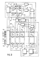
- FIG. 5 has been shown to be considered with respect to FIG. 3, another alternative embodiment of the reception and processing channels. Indeed, if it is not essential to separately access each of the n delayed signals, other architectures than those described so far are possible.
- FIG. 5 shows in particular, part of these channels is now digital and successively comprises a circuit 71 for analog-digital conversion, a circuit 72 for focusing at the reception (these circuits 71 and 72 are here on 1 bit, circuit 71 converting the signal which it delivers, for example on 8 bits, into a signal on 1 bit, keeping only the sign bit), and a circuit correlation 73 performing as previously the determination of the delays to be memorized and to be used for correction, while the rest of the reception and processing channels remain analog, with successively a voltage-current converter 74, a controllable connection establishment circuit 75 (said "cross-switch" circuit, in English), and an addition circuit 76 consisting of an analog line which directly adds the received currents.
- the sequencer 34 controls on the one hand the focusing circuit 72
Landscapes
- Engineering & Computer Science (AREA)
- Computer Networks & Wireless Communication (AREA)
- Physics & Mathematics (AREA)
- General Physics & Mathematics (AREA)
- Radar, Positioning & Navigation (AREA)
- Remote Sensing (AREA)
- Investigating Or Analyzing Materials By The Use Of Ultrasonic Waves (AREA)
- Ultra Sonic Daignosis Equipment (AREA)
- Image Analysis (AREA)
- Image Processing (AREA)
- Measurement Of Velocity Or Position Using Acoustic Or Ultrasonic Waves (AREA)
Applications Claiming Priority (4)
| Application Number | Priority Date | Filing Date | Title |
|---|---|---|---|
| FR9006852A FR2662815A1 (fr) | 1990-06-01 | 1990-06-01 | Procede et appareil d'examen de milieux par echographie ultrasonore. |
| FR9006852 | 1990-06-01 | ||
| FR9100558 | 1991-01-18 | ||
| FR9100558 | 1991-01-18 |
Publications (2)
| Publication Number | Publication Date |
|---|---|
| EP0459583A1 true EP0459583A1 (de) | 1991-12-04 |
| EP0459583B1 EP0459583B1 (de) | 1994-12-21 |
Family
ID=26228048
Family Applications (1)
| Application Number | Title | Priority Date | Filing Date |
|---|---|---|---|
| EP91201273A Expired - Lifetime EP0459583B1 (de) | 1990-06-01 | 1991-05-29 | Ultraschallbildgerät mit adaptiver Phasenaberrationskorrektur |
Country Status (5)
| Country | Link |
|---|---|
| US (1) | US5184623A (de) |
| EP (1) | EP0459583B1 (de) |
| JP (1) | JP3352098B2 (de) |
| DE (1) | DE69106049T2 (de) |
| IL (1) | IL98279A (de) |
Cited By (1)
| Publication number | Priority date | Publication date | Assignee | Title |
|---|---|---|---|---|
| EP0520563A1 (de) * | 1991-06-28 | 1992-12-30 | Laboratoires D'electronique Philips S.A.S. | Ultraschall-Echographie mit adaptiver Phasenaberrationkorrektur |
Families Citing this family (22)
| Publication number | Priority date | Publication date | Assignee | Title |
|---|---|---|---|---|
| US5348013A (en) * | 1990-08-29 | 1994-09-20 | Kabushiki Kaisha Toshiba | Ultrasonic diagnostic apparatus capable of acquiring high quality image by correcting phase distortion contained in ultrasonic pulses |
| US5331964A (en) * | 1993-05-14 | 1994-07-26 | Duke University | Ultrasonic phased array imaging system with high speed adaptive processing using selected elements |
| US5322068A (en) * | 1993-05-21 | 1994-06-21 | Hewlett-Packard Company | Method and apparatus for dynamically steering ultrasonic phased arrays |
| US5581517A (en) * | 1994-08-05 | 1996-12-03 | Acuson Corporation | Method and apparatus for focus control of transmit and receive beamformer systems |
| US5551433A (en) * | 1994-08-05 | 1996-09-03 | Acuson Corporation | Method and apparatus for a geometric aberration transform in an adaptive focusing ultrasound beamformer system |
| US5570691A (en) * | 1994-08-05 | 1996-11-05 | Acuson Corporation | Method and apparatus for real-time, concurrent adaptive focusing in an ultrasound beamformer imaging system |
| US6027447A (en) * | 1995-01-23 | 2000-02-22 | Commonwealth Scientific And Industrial Research Organisation | Phase and/or amplitude aberration correction for imaging |
| US6120450A (en) * | 1995-01-23 | 2000-09-19 | Commonwealth Scientific And Industrial Research Organisation | Phase and/or amplitude aberration correction for imaging |
| US5590658A (en) | 1995-06-29 | 1997-01-07 | Teratech Corporation | Portable ultrasound imaging system |
| US7500952B1 (en) * | 1995-06-29 | 2009-03-10 | Teratech Corporation | Portable ultrasound imaging system |
| US8241217B2 (en) | 1995-06-29 | 2012-08-14 | Teratech Corporation | Portable ultrasound imaging data |
| US5995447A (en) * | 1997-05-14 | 1999-11-30 | Gas Research Institute | System and method for processing acoustic signals to image behind reflective layers |
| US6021093A (en) * | 1997-05-14 | 2000-02-01 | Gas Research Institute | Transducer configuration having a multiple viewing position feature |
| US6125079A (en) * | 1997-05-14 | 2000-09-26 | Gas Research Institute | System and method for providing dual distance transducers to image behind an acoustically reflective layer |
| US6002639A (en) * | 1997-05-14 | 1999-12-14 | Gas Research Institute | Sensor configuration for nulling reverberations to image behind reflective layers |
| WO1999044504A1 (en) * | 1998-03-06 | 1999-09-10 | Hitachi Medical Corporation | Ultrasonic video apparatus |
| FR2839157A1 (fr) * | 2002-04-30 | 2003-10-31 | Koninkl Philips Electronics Nv | Systeme d'imagerie ultrasonore a haute resolution laterale |
| NO325153B1 (no) * | 2003-05-05 | 2008-02-11 | Clampon As | Fremgangsmate og system til a registrere strukturforhold i et akustisk ledende materiale ved bruk av krysspeilinger |
| US20060254359A1 (en) * | 2005-01-14 | 2006-11-16 | Pierre Langlois | Hand-held flaw detector imaging apparatus |
| US20100228130A1 (en) * | 2009-03-09 | 2010-09-09 | Teratech Corporation | Portable ultrasound imaging system |
| US20120071762A1 (en) * | 2010-09-21 | 2012-03-22 | Fujifilm Corporation | Ultrasound diagnostic apparatus |
| JP7433172B2 (ja) * | 2020-09-10 | 2024-02-19 | 三菱重工業株式会社 | 超音波検査方法、超音波検査装置およびプログラム |
Citations (2)
| Publication number | Priority date | Publication date | Assignee | Title |
|---|---|---|---|---|
| EP0256481A1 (de) * | 1986-08-20 | 1988-02-24 | Siemens Aktiengesellschaft | Verfahren und Einrichtung zur adaptiven Fokussierung bei einem medizinischen Ultraschall-Bildgabegerät |
| EP0320303A2 (de) * | 1987-12-11 | 1989-06-14 | General Electric Company | Bildung eines kohärenten Bündels |
Family Cites Families (1)
| Publication number | Priority date | Publication date | Assignee | Title |
|---|---|---|---|---|
| US4471785A (en) * | 1982-09-29 | 1984-09-18 | Sri International | Ultrasonic imaging system with correction for velocity inhomogeneity and multipath interference using an ultrasonic imaging array |
-
1991
- 1991-05-27 IL IL9827991A patent/IL98279A/en not_active IP Right Cessation
- 1991-05-29 DE DE69106049T patent/DE69106049T2/de not_active Expired - Fee Related
- 1991-05-29 EP EP91201273A patent/EP0459583B1/de not_active Expired - Lifetime
- 1991-05-31 JP JP15612991A patent/JP3352098B2/ja not_active Expired - Fee Related
- 1991-05-31 US US07/708,942 patent/US5184623A/en not_active Expired - Lifetime
Patent Citations (2)
| Publication number | Priority date | Publication date | Assignee | Title |
|---|---|---|---|---|
| EP0256481A1 (de) * | 1986-08-20 | 1988-02-24 | Siemens Aktiengesellschaft | Verfahren und Einrichtung zur adaptiven Fokussierung bei einem medizinischen Ultraschall-Bildgabegerät |
| EP0320303A2 (de) * | 1987-12-11 | 1989-06-14 | General Electric Company | Bildung eines kohärenten Bündels |
Cited By (1)
| Publication number | Priority date | Publication date | Assignee | Title |
|---|---|---|---|---|
| EP0520563A1 (de) * | 1991-06-28 | 1992-12-30 | Laboratoires D'electronique Philips S.A.S. | Ultraschall-Echographie mit adaptiver Phasenaberrationkorrektur |
Also Published As
| Publication number | Publication date |
|---|---|
| EP0459583B1 (de) | 1994-12-21 |
| JP3352098B2 (ja) | 2002-12-03 |
| US5184623A (en) | 1993-02-09 |
| DE69106049T2 (de) | 1995-07-06 |
| JPH04231033A (ja) | 1992-08-19 |
| IL98279A (en) | 1994-11-11 |
| DE69106049D1 (de) | 1995-02-02 |
Similar Documents
| Publication | Publication Date | Title |
|---|---|---|
| EP0459583B1 (de) | Ultraschallbildgerät mit adaptiver Phasenaberrationskorrektur | |
| EP0383650B1 (de) | Verfahren und Vorrichtung zum Orten und Fokussieren von Wellen | |
| EP0591061B1 (de) | Verfahren und Vorrichtung zur akustischen Prüfung mit Zeitumkehrsignalen | |
| EP0541434A1 (de) | Verfahren und Vorrichtung zur Ultraschallprüfung von Werkzeugen | |
| FR2631707A1 (fr) | Echographe ultrasonore a coherence de phase controlable | |
| FR2851662A1 (fr) | Procede et dispositif de detection de discontinuites dans un milieu | |
| FR2507078A1 (fr) | Procede et dispositif d'echographie ultrasonore | |
| EP0543445A1 (de) | Untersuchungsgerät von Medien mittels Ultraschall-Echographie | |
| FR2493528A1 (fr) | Systeme de detection multivoies a emission diversifiee | |
| EP0872742A1 (de) | Verfahren und Vorrichtung zur Verarbeitung von aus einer Volumenstruktur übertragenen oder gebeugten Signalen reflektierter Wellen zur Erkundung oder Analyse der Struktur | |
| FR2815723A1 (fr) | Procede systeme et sonde pour l'obtention d'images par l'intermediaire d'ondes emises par une antenne apres reflexion de ces ondes au niveau d'un ensemble servant de cible | |
| FR2570837A1 (fr) | Sonde a ultrasons pour balayage sectoriel electronique et echographe incorporant une telle sonde | |
| EP0420346A1 (de) | Ultraschall-Echograph mit digitaler Einrichtung zur Formung des Strahlenbündels im Empfangsfall | |
| EP0106418B1 (de) | Gerät zum Untersuchen von Medien mittels Ultraschallechographie | |
| EP1430299B1 (de) | Vorrichtung zur strukturanalyse eines materials | |
| EP0825453A1 (de) | Verfahren und Anordnung zur Bearbeitung von Signalen, welche durch ein Volumenstruktur reflektierte oder übertragene Wellen darstellen, um eine Forschung und Analyse der Struktur auszuführen | |
| EP0520563B1 (de) | Ultraschall-Echographie mit adaptiver Phasenaberrationkorrektur | |
| EP0040566B1 (de) | Echographisches Gerät mit dynamischer Fokussierung und Sektorabtastung | |
| EP0457396A1 (de) | Gerät zur Festechounterdrückung für einen Ultraschallechograph | |
| EP3400457B1 (de) | Verfahren zum löschen eines signals aus einem bordradar | |
| FR2901365A1 (fr) | Sonar frontal ameliore | |
| EP1649449A1 (de) | Oberflächenwellen-abbildungsverfahren und einrichtung | |
| FR2517830A1 (fr) | Recepteur de signaux magnetiques et processeur destine a fournir des donnees de frequence des signaux recus | |
| FR2604843A1 (fr) | Dispositif de reception d'emissions de radio, de television ou d'echos radar | |
| WO1982000061A1 (fr) | Dispositif recepteur pour echographe a sonde ultrasonore multi-elements et echographe ainsi equipe |
Legal Events
| Date | Code | Title | Description |
|---|---|---|---|
| PUAI | Public reference made under article 153(3) epc to a published international application that has entered the european phase |
Free format text: ORIGINAL CODE: 0009012 |
|
| AK | Designated contracting states |
Kind code of ref document: A1 Designated state(s): DE FR GB IT |
|
| 17P | Request for examination filed |
Effective date: 19920604 |
|
| 17Q | First examination report despatched |
Effective date: 19931104 |
|
| GRAA | (expected) grant |
Free format text: ORIGINAL CODE: 0009210 |
|
| AK | Designated contracting states |
Kind code of ref document: B1 Designated state(s): DE FR GB IT |
|
| REF | Corresponds to: |
Ref document number: 69106049 Country of ref document: DE Date of ref document: 19950202 |
|
| ITF | It: translation for a ep patent filed | ||
| GBT | Gb: translation of ep patent filed (gb section 77(6)(a)/1977) |
Effective date: 19950307 |
|
| PLBE | No opposition filed within time limit |
Free format text: ORIGINAL CODE: 0009261 |
|
| STAA | Information on the status of an ep patent application or granted ep patent |
Free format text: STATUS: NO OPPOSITION FILED WITHIN TIME LIMIT |
|
| 26N | No opposition filed | ||
| REG | Reference to a national code |
Ref country code: FR Ref legal event code: CJ Ref country code: FR Ref legal event code: CD |
|
| REG | Reference to a national code |
Ref country code: FR Ref legal event code: D6 |
|
| REG | Reference to a national code |
Ref country code: GB Ref legal event code: IF02 |
|
| REG | Reference to a national code |
Ref country code: FR Ref legal event code: D6 |
|
| REG | Reference to a national code |
Ref country code: GB Ref legal event code: 746 Effective date: 20021107 |
|
| PGFP | Annual fee paid to national office [announced via postgrant information from national office to epo] |
Ref country code: FR Payment date: 20040527 Year of fee payment: 14 |
|
| PGFP | Annual fee paid to national office [announced via postgrant information from national office to epo] |
Ref country code: GB Payment date: 20040528 Year of fee payment: 14 |
|
| PGFP | Annual fee paid to national office [announced via postgrant information from national office to epo] |
Ref country code: DE Payment date: 20040714 Year of fee payment: 14 |
|
| PG25 | Lapsed in a contracting state [announced via postgrant information from national office to epo] |
Ref country code: IT Free format text: LAPSE BECAUSE OF NON-PAYMENT OF DUE FEES;WARNING: LAPSES OF ITALIAN PATENTS WITH EFFECTIVE DATE BEFORE 2007 MAY HAVE OCCURRED AT ANY TIME BEFORE 2007. THE CORRECT EFFECTIVE DATE MAY BE DIFFERENT FROM THE ONE RECORDED. Effective date: 20050529 Ref country code: GB Free format text: LAPSE BECAUSE OF NON-PAYMENT OF DUE FEES Effective date: 20050529 |
|
| PG25 | Lapsed in a contracting state [announced via postgrant information from national office to epo] |
Ref country code: DE Free format text: LAPSE BECAUSE OF NON-PAYMENT OF DUE FEES Effective date: 20051201 |
|
| GBPC | Gb: european patent ceased through non-payment of renewal fee |
Effective date: 20050529 |
|
| PG25 | Lapsed in a contracting state [announced via postgrant information from national office to epo] |
Ref country code: FR Free format text: LAPSE BECAUSE OF NON-PAYMENT OF DUE FEES Effective date: 20060131 |
|
| REG | Reference to a national code |
Ref country code: FR Ref legal event code: ST Effective date: 20060131 |