EP0459610B1 - Fräswerkzeug für Futterrohre - Google Patents
Fräswerkzeug für Futterrohre Download PDFInfo
- Publication number
- EP0459610B1 EP0459610B1 EP91302351A EP91302351A EP0459610B1 EP 0459610 B1 EP0459610 B1 EP 0459610B1 EP 91302351 A EP91302351 A EP 91302351A EP 91302351 A EP91302351 A EP 91302351A EP 0459610 B1 EP0459610 B1 EP 0459610B1
- Authority
- EP
- European Patent Office
- Prior art keywords
- blades
- pipe
- piston
- casing
- milling
- Prior art date
- Legal status (The legal status is an assumption and is not a legal conclusion. Google has not performed a legal analysis and makes no representation as to the accuracy of the status listed.)
- Expired - Lifetime
Links
Images



Classifications
-
- E—FIXED CONSTRUCTIONS
- E21—EARTH OR ROCK DRILLING; MINING
- E21B—EARTH OR ROCK DRILLING; OBTAINING OIL, GAS, WATER, SOLUBLE OR MELTABLE MATERIALS OR A SLURRY OF MINERALS FROM WELLS
- E21B23/00—Apparatus for displacing, setting, locking, releasing or removing tools, packers or the like in boreholes or wells
- E21B23/004—Indexing systems for guiding relative movement between telescoping parts of downhole tools
- E21B23/006—"J-slot" systems, i.e. lug and slot indexing mechanisms
-
- E—FIXED CONSTRUCTIONS
- E21—EARTH OR ROCK DRILLING; MINING
- E21B—EARTH OR ROCK DRILLING; OBTAINING OIL, GAS, WATER, SOLUBLE OR MELTABLE MATERIALS OR A SLURRY OF MINERALS FROM WELLS
- E21B29/00—Cutting or destroying pipes, packers, plugs or wire lines, located in boreholes or wells, e.g. cutting of damaged pipes, of windows; Deforming of pipes in boreholes or wells; Reconditioning of well casings while in the ground
- E21B29/002—Cutting, e.g. milling, a pipe with a cutter rotating along the circumference of the pipe
- E21B29/005—Cutting, e.g. milling, a pipe with a cutter rotating along the circumference of the pipe with a radially-expansible cutter rotating inside the pipe, e.g. for cutting an annular window
-
- E—FIXED CONSTRUCTIONS
- E21—EARTH OR ROCK DRILLING; MINING
- E21B—EARTH OR ROCK DRILLING; OBTAINING OIL, GAS, WATER, SOLUBLE OR MELTABLE MATERIALS OR A SLURRY OF MINERALS FROM WELLS
- E21B10/00—Drill bits
- E21B10/26—Drill bits with leading portion, i.e. drill bits with a pilot cutter; Drill bits for enlarging the borehole, e.g. reamers
- E21B10/32—Drill bits with leading portion, i.e. drill bits with a pilot cutter; Drill bits for enlarging the borehole, e.g. reamers with expansible cutting tools
- E21B10/322—Drill bits with leading portion, i.e. drill bits with a pilot cutter; Drill bits for enlarging the borehole, e.g. reamers with expansible cutting tools cutter shifted by fluid pressure
Definitions
- Oil wells and the like are commonly provided with a steel pipe casing lining the well bore. It is also common in some types of well completions to provide an inner steel casing within the outer steel casing through at least a portion of the well depth.
- the inner casing may hang free within the outer casing or may be cemented in place by a cement grout injected between the two casings.
- the casing in a well bore is in the form of steel pipe with male threads at each end, with adjacent pieces of pipe being interconnected by pipe couplings external to the pipe.
- the casing string may have a diameter two or three centimeters greater at the location of a coupling than it does through the length of a piece of pipe.
- Casing mills are typically kept centered in the casing being milled by a stabilizer or multiple stabilizers above and/or below the casing mill, thereby assuring that all of the steel of the casing string is milled away.
- the problem of milling into the outer casing in sections between couplings may be alleviated by using undersize stabilizers which permit the casing mill to "wander" within the inner casing.
- undersize stabilizers which permit the casing mill to "wander" within the inner casing.
- the outer casing When the outer casing is encountered by the mill, it tends to push the mill away from the outer casing and minimize damage to the outer casing.
- a problem with this is that there may be insufficient stabilization to properly mill the couplings between sections of pipe. The rate of milling is also reduced, thereby increasing cost.
- a casing mill for practice of this technique has a tubular body with a diameter smaller than the inside diameter of the casing to be milled.
- a first group of milling blades fixed on the body extend to a diameter corresponding to the outside diameter of the pipe to be milled.
- a second group of milling blades are mounted on the body for motion between a retracted position having a diameter smaller than the inside diameter of the pipe, and an extended position at a diameter corresponding to the outside diameter of a coupling between sections of pipe. Both sets of blades have material for cutting the end of the metal casing.
- a "switch”, preferably activated by drilling fluid pressure, is used for selectively moving the movable blades between the retracted and extended positions. The mill is stabilized so that it remains centered within the casing being milled.
- FIGS. 1 and 2 provide external side views of an exemplary casing mill, as provided in practice of this invention, in two positions as it mills pipe 16 and coupling 15, respectively, in a well bore.
- portions of the length of the casing mill have been deleted for convenience of illustration. It will be recognized that the total length of the casing mill may be substantially more than suggested by the portions illustrated. For example, for milling standard 13-3/8 inch (34 cm) casing, the total length of the assembly is in the order of six meters. It will also be apparent that, as is commonplace in downhole tools, the casing mill is made from several sections threaded together.
- a conventional stinger 10 having a conical end for entering the end of the casing to be milled.
- the stinger may be essentially smooth or may include tungsten carbide or similar cutting material for milling occasional junk within the casing.
- the outside surface of the stinger typically has a diameter only slightly smaller than the inside diameter of the casing for providing stabilization at the lower end of the casing mill. Excessive stabilization is avoided by providing a small degree of flexibility in the tubular body connecting the head of the stinger with the lower cutting portion of the casing mill.
- the stinger is a coupling milling section 11 on which are mounted a plurality (typically, three) of movable cutting blades 12.
- the movable blades are movable between a retracted position, as illustrated in FIG. 1, and an extended position, as illustrated in FIG. 2.
- the coupling mill section is a mechanism 13 for switching the movable blades between the extended and retracted positions.
- the switching mechanism is operated by the hydraulic pressure of drilling fluid or "mud.”
- a central blade-type stabilizer 14 having an outside diameter corresponding to the inside diameter of the pipe 16 to be milled for keeping the casing mill centered within the pipe.
- central stabilizer 14 is a pipe milling section having a plurality (typically from three to eight) of pipe cutting blades 17 extending radially from the body of the casing mill.
- Each of the fixed blades comprises a steel fin with a plurality of cemented tungsten carbide inserts brazed on the face of the fin to engage the steel of the end of the casing with a negative rake of several degrees suitable for rapid and efficient milling of the steel.
- the arrangement of tungsten carbide inserts on the fin is now conventional for a casing mill.
- the outside diameter of the group of fixed blades corresponds to the outside diameter of the pipe being milled.
- the diameter of the blades does not need to be exactly the same as the diameter of the pipe, but may be a millimeter or two larger or smaller, and still successfully mill all of the steel of the pipe.
- a conventional spiral stabilizer 18 which is optional but desirable.
- the outside diameter of the upper stabilizer corresponds roughly to the diameter of the hole after the pipe is milled.
- conventional drill collars (not illustrated) or the like are connected at the lower end of the drill string for providing sufficient weight for the milling operation.
- the portion of the casing that is not embedded in cement is cut or backed off and retrieved from the well.
- some of the casing embedded in cement may be milled with conventional pilot mills or casing mills where there is little or no hazard of damage to the outer casing.
- a conventional fixed size pilot mill may be quite acceptable for milling the inner casing where centralizers had been used at the time of original installation of the inner casing.
- the dual outside diameter casing mill provided in practice of this invention may be reserved for those portions of the hole depth where problems in use of conventional pilot mills might be expected or are unexpectedly encountered.
- the coupling milling blades 12 are retained in their retracted position.
- the stinger 10 enters the inner casing, and the mill is lowered until the fixed pipe cutting blades 17 encounter the end of the pipe.
- the movable blades are extended by application of hydraulic pressure of drilling mud when the switching mechanism is in the appropriate position.
- the initial setting of the switching mechanism may not be known to the rig operator.
- the blades may or may not become extended. This can be tested before milling commences.
- the drill string is raised a distance in excess of the spacing between the movable blades and fixed blades. Mud circulation is then commenced and the drill string is lowered slowly without rotation to see if the movable blades touch the end of the casing. If the depth where the end of the casing is encountered (as shown by the weight indicator on the drill rig) is the same as before, it is known that the movable blades are retracted and milling of the pipe may commence. On the other hand, if the end of the pipe is encountered at an elevation higher than before corresponding to the distance between the blades, it is known that the movable blades are in their extended position. In that event, mud circulation is stopped for retracting the blades, and mud circulation recommenced. The switching mechanism leaves the blades in their retracted position, and milling of the pipe may then commence.
- Milling of pipe with the fixed blades 17 is continued to a short distance above the elevation of a pipe coupling 15.
- the mud pumps are then shut down.
- the drill string is raised a short distance more than the spacing between the fixed and movable blades, and the mud pumps are turned back on. This causes the movable blades to be biased toward their extended position, and milling is resumed.
- the movable blades move to their extended position and have a sufficient outside diameter for milling the coupling between pipes.
- mud circulation is again interrupted and the tool lifted enough to permit the movable blades to retract. Mud circulation is resumed and the mill is lowered a distance corresponding to the spacing between the blades to resume milling the next piece of pipe with the fixed blades. This cycle is repeated for milling each coupling through the troublesome section of the casing.
- the distance between the fixed blades and movable blades and the differential fluid pressure drops, depending on whether the movable blades are retracted or extended, provide positive indicators of the mode of operation of the dual diameter casing mill.
- FIGS. 3 to 5 illustrate an exemplary switching mechanism for selecting the modes of operation of the movable blades in their retracted or extended position.
- the left-hand side of each of FIGS. 3 and 4 illustrates the interior of the switching mechanism when it is in its switching position between the blade-extended and blade-retracted positions.
- the right-hand side of FIG. 3 illustrates the position of the parts of the switching mechanism when in the blade-retracted position.
- the right-hand side of FIG. 4 illustrates the mechanism in the blade-extended position.
- the entire switching mechanism is in a tubular housing 21 which is threaded at each end for connection between other portions of the casing mill.
- a movable piston 22 can slide longitudinally in the housing and is sealed to the housing at its upper end by O-rings 23.
- a spring support sleeve 24 Surrounding the lower end of the piston is a spring support sleeve 24 which is sealed to the housing by an O-ring 26. The inside of the spring support sleeve is sealed to the outside of the piston by O-rings 27.
- a compression spring 28 fits in an annular chamber between the end of the spring support sleeve and a downwardly facing shoulder 29 on the piston.
- Bearings 31 are provided at each end of the spring for facilitating rotation of the piston.
- a screened opening 32 provides venting for the annular spring chamber and prevents rock fragments from entering the chamber.
- the lower end of the spring support sleeve 24 is supported in the housing on a stinger body 33.
- the stinger body has a rim 34 in the housing and three spokes 36 supporting a central hub 37. Drilling fluid may flow through the openings between the spokes.
- the stinger body is connected to an annular cap 38 by cap screws 39. The exterior surface of the cap is tapered for forcing a bail 41 into an annular groove in the housing and locking the stinger assembly in place.
- a stinger plug 42 is assembled on the hub of the stinger body.
- the piston 22 When the piston 22 is in its lowermost position with the movable arms retracted, the lower end of the piston engages the upper end of the plug, forming a closure which prevents substantial mud flow circulation through the full length of the switching mechanism (right-hand side of FIG. 3).
- the upper end of the piston clears three bypass nozzles 43 extending through the wall of the housing. The bypass nozzles eject drilling mud into the annulus outside of the casing mill for cooling and removing chips from the fixed milling blades which are above the switching mechanism.
- the position of the piston is limited by a pair of piston guide screws 44 threaded through the wall of the housing.
- Each of the guide screws has a cylindrical end 46 which fits into a zigzag ball-pen slot 47 in the outside wall of the piston. This is referred to as a ball-pen slot by analogy to a mechanism used for alternately extending or retracting the tip of some ballpoint pens.
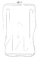
- FIG. 5 is a face view of one-half of the ball-pen slot.
- the other half of the slot, which is not illustrated, is a repetition of the illustrated portion.
- the ball-pen slot has switching pockets 48 90° apart at the lowest extent of the slot.
- a pair of elongated retracted position pockets 49 are spaced 180° apart around an upper part of the piston and 45° offset from the switching pockets.
- a pair of extended position pockets 51 are 180° apart and 90° between the retracted position pockets 49. The extended position pockets extend a shorter distance up the piston than the retracted position pockets.
- the spring 28 drives the piston 22 to its uppermost position (left side of FIGS. 3 and 4) and the piston guide screws 44 are in the switching pockets 48 of the ball-pen slot.
- the pressure on the top of the step piston increases while the pressure under the head of the postion is exposed to the lower pressure of the annulus beyond the fluid exit nozzles (via the spring chamber).
- the differential fluid pressure across the step piston drives the piston downwardly.
- the cylindrical ends of the drive screws each engage a diagonal upper camming surface 52 in the ball-pen slot. This causes the piston to rotate, and depending on which two of the four switching pockets the guide screws happen to have been in, the guide screws enter either the retracted-position pockets 49 or extended-position pockets 51, thereby limiting the stroke of the piston, depending on the depth of the respective pockets.
- the piston can move downwardly further when in its retracted position and the guide screws are in the retracted position pockets 49.
- the flow cross-sections through the nozzle 68 in the coupling mill and through the nozzles 43 adjacent to the casing mill blades are different, so that different pressure drops may be sensed for indicating whether the casing mill is in its retracted or extended mode of operation.
- FIG. 6 illustrates a longitudinal cross-section through an exemplary mechanism for extending the movable arms or cutting blades 12 of the casing mill for milling a pipe coupling.
- a mechanism is conventional and exemplary of arm-extension mechanisms which may be used in practice of this invention.
- the body 56 of the coupling mill section of the casing mill is threaded at the ends for assembly between the stinger 10 and switching mechanism 13.
- a piston stem 57 secured to a piston head 58 is mounted in the body for translation along its length.
- the piston is biased upwardly by a piston spring 59.
- the piston is moved downwardly by drilling fluid pressure on the piston head.
- Three cutting blades 12 are in the form of arms mounted on pivot pins 61 secured in the body.
- the outer end of each arm has a plurality of cemented tungsten carbide cutting elements 62 brazed on the face of the arm at an angle for providing an appropriate negative rake for cutting the steel of the pipe and coupling.
- At the inner end of each arm there are a few gear teeth 63 which engage complementary teeth 64 in the form of ridges around the piston stem 57.
- the cutting forces tend to keep the arms fully open against arm stops 66.
- the tool should, therefore, be lifted off of the cutting face when the mud pumps are turned off and it is desired to retract the arms. If the arms should get stuck toward their extended positions, they are easily pressed toward the retracted position by lifting the tool so that the arms engage a portion of the hole where only the fixed blades have been used.
- drilling fluid flows through the hollow piston and out the lower end for cooling the cutting blades and removing chips.
- the opening through the piston is reduced by a stinger 67. The resultant higher pressure required to pump the drilling fluid through the piston indicates positively whether the arms are extended.
- adjustable and fixed blades may be arranged at the same elevation on the casing mill or at different elevations. Having the movable blades beneath the fixed blades as in the present embodiment provides a ready ability to distinguish whether the blades are extended or retracted. This arrangement is also preferred for stabilization of the casing mill. Having the two cutting structures at different elevations also permits the use of larger cutting surfaces and enhances life time of the casing mill.
- the zigzag ball-pen slot in the illustrated embodiment is provided around the perimeter of the piston with guides extending inwardly through the housing wall to fit into the slot.
- a slot may be provided within the housing and be engaged by guide means extending outwardly from the piston.
- Other means may be employed for switching the piston between the extended and retracted positions.
Landscapes
- Life Sciences & Earth Sciences (AREA)
- Engineering & Computer Science (AREA)
- Geology (AREA)
- Mining & Mineral Resources (AREA)
- Physics & Mathematics (AREA)
- Environmental & Geological Engineering (AREA)
- Fluid Mechanics (AREA)
- General Life Sciences & Earth Sciences (AREA)
- Geochemistry & Mineralogy (AREA)
- Crushing And Grinding (AREA)
- Excavating Of Shafts Or Tunnels (AREA)
- Earth Drilling (AREA)
Claims (15)
- Eine Fräsmaschine zum Fräsen von Futterrohren in Öltiefbohrlöchern mit Rohrsegmenten, die durch externe Verbindungsstücke verkuppelt sind, bestehend aus einer Einrichtung (14) zur Stabilisierung des in einem zu fräsenden Rohr zentrierten Gehäuses, wobei eine Vielzahl feststehender Klingen (17) auf dem Gehäuse einen Durchmesser aufweist, der zum reinen Rohrfräsen ausreicht, mit folgenden Merkmalen:einer Vielzahl von beweglichen Klingen (12) am Gehäuse, die innerhalb eines Durchmessers bewegt werden können, der zum Fräsen sowohl des Rohrs als auch der Rohrverbinder ausreicht; sowieeinem Schaltmechanismus (13) in dem Gehäuse zur Bewegung der beweglichen Klingen in einem Durchmesser, der zum Fräsen sowohl des Rohrs als auch der Rohrverbinder ausreicht.
- Eine Fräsmaschine für Futterrohre gemäß dem unter Beanspruchung 1 dargelegten Anspruch, einschließlich eines Stabilisators (14) zwischen den beweglichen Klingen (12) und den Klingen (17) zum reinen Rohrfräsen.
- Eine Fräsmaschine für Futterrohre wie bei den beiden vorausgehenden Ansprüchen, wobei die beweglichen Klingen (12) sich unter den Klingen (17) zum reinen Rohrfräsen befinden.
- Eine Fräsmaschine für Futterrohre gemäß dem unter Beanspruchung 3 dargelegten Anspruch, die darüber hinaus Vorrichtungen (22, 33, 42, 43) zur Lenkung des Bohrflüssigkeitsstroms zu den unteren Klingen aufweist, wenn diese ausgefahren sind, sowie zur Umlenkung des Bohrflüssigkeitsstroms zu den oberen Klingen, wenn die unteren zurückgezogen sind.
- Eine Fräsmaschine für Futterrohre gemäß Darlegung in der obigen Beanspruchung, wobei der Schaltmechanismus sich wie folgt zusammensetzt:aus einem Kolben (22) in dem Gehäuse, der sich zwischen einer oberen und einer unteren Position bewegen läßt;einer Vorrichtung (33), die mit dem Kolben bei der Lenkung des Bohrflüssigkeitsstroms zu den beweglichen Klingen (12) zusammenwirkt, wenn der Kolben sich in der oberen Position befindet; sowieeiner Vorrichtung (42, 43), die mit dem Kolben bei der Umlenkung des Bohrflüssigkeitsstroms weg von den beweglichen Klingen zusammenwirkt, wenn der Kolben sich in der unteren Position befindet.
- Eine Futterrohrvorrichtung gemäß Darlegung unter Beanspruchung 5, bei der der Schaltmechanismus des weiteren eine Vorrichtung aufweist, die zur Bewegung des Kolbens (22) auf eine neutrale Schaltposition zwischen den oberen und unteren Positionen dient, welche sich oberhalb der oberen Position befindet.
- Eine Fräsmaschine für Futterrohre gemäß Darlegung unter Beanspruchung 5 oder 6, einschließlich:eines zickzackförmigen kugelschreiberartigen Schlitzes (47) am Umfang des Kolbens (22) und einer Vorrichtung (46), die den Schlitz zur Führung des Kolbens zwischen seiner oberen Position, seiner unteren Position und einer neutralen Schaltposition einrückt; sowieeiner Vorrichtung (52,53) zur Rotation des Kolbens zur abwechselnden Stellung des Kolbens auf seine obere bzw. untere Stellung.
- Eine Fräsmaschine für Futterrohre gemäß Darlegung unter Beanspruchung 1 bis 4, wobei der Schaltmechanismus folgendes umfaßt:einen hohlen Kolben (22) in dem Gehäuse;einen zickzackförmigen kugelachreiberartigen Schlitz (47) am Umfang des Kolbens; einschließlich Nischen - abwechselnd für die ausgefahrene Position (51) bzw. für die zurückgezogene Position (49) an einem Ende des Zickzacks bzw. für die neutrale Schaltposition (48) am anderen Ende des Zickzacks;einen Federungsmechanismus (28) zur Vorspannung des Kolbens auf die neutrale Schaltposition;eine Vorrichtung (42) zur Einschränkung des Flüssigkeitsstroms zu den beweglichen Klingen (12), wenn der Kolben sich in seiner unteren Position befindet; undeine Vorrichtung (33), die den Flüssigkeitsstrom den beweglichen Klingen zufließen läßt, wenn der Kolben sich in der oberen Position befindet.
- Eine Fräsmaschine für Futterrohre gemäß dem unter Beanspruchung 8 dargelegten Anspruch, wobei die Vorrichtung zur Einschränkung des Flüssigkeitsstroms zu der zweiten Vielzahl von Klingen einen Stopfen (42) zum Schließen des unteren Endes des hohlen Kolbens (22) enthält, wenn sich der Kolben in der unteren Stellung befindet.
- Eine Fräsmaschine für Futterrohre gemäß dem unter Beanspruchung 8 oder 9 dargelegten Anspruch, die darüber hinaus eine Vorrichtung (43) zum Umlenken des Flüssigkeitsstroms zu der ersten Klingengruppe (17) umfaßt, wenn sich der Kolben in der unteren Stellung befindet.
- Eine Fräsmaschine für Futterrohre gemäß eines beliebigen der unter Beanspruchung 8 bis 10 dargelegten Ansprüche, wobei der Kolben in seiner oberen Position die Vorrichtung (43) zur Lenkung des Flüssigkeitsstroms zu der ersten Klingengruppe (17) blockiert und wobei das untere Kolbenende sich von dem Stopfen (42) entfernt befindet.
- Eine Methode zum Fräsen eines Futterrohrs mit einer Vielzahl von Rohrsegmenten, die durch externe Verbindungsstücke miteinander verkuppelt sind, und die durch folgende Stufen gekennzeichnet ist:Fräsen eines Rohrsegments mit feststehenden Klingen auf einem Werkzeugkörper auf einer Höhe oberhalb eines Verbindungsstücks, wobei die feststehenden Klingen eine begrenzte radiale Ausdehnung aufweisen, so daß sie nur Rohrsegmente fräsen können;Ausfahren von beweglichen Klingen an dem Werkzeugkörper; Fräsen des Verbindungsstücks mit Hilfe der ausgefahrenen beweglichen Klingen;Zurückziehen der beweglichen Klingen sowie Fräsen des nächsten Rohrsegments unterhalb des Rohrverbinders mit den feststehenden Klingen.
- Eine Methode gemäß Darlegung unter Beanspruchung 12, wobei die beweglichen Klingen sich unterhalb der feststehenden Klingen befinden, die den Verfahrensschritt beinhaltet, das Werkzeug mit den beweglichen Klingen im zurückgezogenen Zustand zu heben, bis die beweglichen Klingen sich über dem gefrästen Ende des Futterrohrs befinden und danach die beweglichen Klingen auszufahren.
- Eine Fräsmaschine für Futterrohre gemäß dem unter Beanspruchung 1 dargelegten Anspruch, einschließlich:stabilisierungsvorrichtung (14), die dazu dient, die Fräsmaschine in dem zu fräsenden Rohr zentriert zu halten;wobei die feststehenden Klingen (17) zum reinen Rohrfräsen am Körper befestigt sind und sich auf einen Durchmesser ausfahren lassen, der dem äußeren Durchmesser des zu fräsenden Rohrs entspricht, wobei die feststehenden Klingen ein Zerspanungsmaterial zum Fräsen des Metallrohrendes enthalten; und wobei die beweglichen Klingen (12) an den Körper montiert sind zur Bewegung zwischen einer zurückgezogenen Position mit einem Durchmesser, der kleiner ist als der innere Durchmesser des zu fräsenden Rohrs und einer ausgefahrenen Position mit einem Durchmesser, der dem äußeren Durchmesser eines zu fräsenden Rohrverbinders entspricht, wobei die beweglichen Klingen ein Zerspanungsmaterial zum Fräsen des Metallrohrendes und eines umgebenden Rohrverbinders aufweisen.
- Eine Fräsmaschine zum Fräsen von Futterrohren in Öltiefbohrlöchern mit Rohrsegmenten, die durch externe Verbindungsstücke verkuppelt sind, einschließlich:eines Gehäuses;einer Vorrichtung (14) zur Stabilisierung des Gehäuses in zentrierter Lage in dem zu fräsenden Rohr;einer Vielzahl von Klingen, die an das Gehäuse montiert sind und sich zwischen einer zurückgezogenen Position, in der sie nur Rohr fräsen, und einer ausgefahrenen Position, in der sie sowohl Rohr als auch Rohrverbinder fräsen, bewegen lassen.
Applications Claiming Priority (2)
| Application Number | Priority Date | Filing Date | Title |
|---|---|---|---|
| US07/530,107 US5010955A (en) | 1990-05-29 | 1990-05-29 | Casing mill and method |
| US530107 | 1990-05-29 |
Publications (3)
| Publication Number | Publication Date |
|---|---|
| EP0459610A2 EP0459610A2 (de) | 1991-12-04 |
| EP0459610A3 EP0459610A3 (en) | 1992-10-28 |
| EP0459610B1 true EP0459610B1 (de) | 1996-07-03 |
Family
ID=24112472
Family Applications (1)
| Application Number | Title | Priority Date | Filing Date |
|---|---|---|---|
| EP91302351A Expired - Lifetime EP0459610B1 (de) | 1990-05-29 | 1991-03-19 | Fräswerkzeug für Futterrohre |
Country Status (4)
| Country | Link |
|---|---|
| US (1) | US5010955A (de) |
| EP (1) | EP0459610B1 (de) |
| DE (1) | DE69120605D1 (de) |
| NO (1) | NO910988L (de) |
Families Citing this family (87)
| Publication number | Priority date | Publication date | Assignee | Title |
|---|---|---|---|---|
| US5101895A (en) * | 1990-12-21 | 1992-04-07 | Smith International, Inc. | Well abandonment system |
| GB9124486D0 (en) * | 1991-11-18 | 1992-01-08 | Appleton Robert P | Downhole tools(wells) |
| US5282509A (en) * | 1992-08-20 | 1994-02-01 | Conoco Inc. | Method for cleaning cement plug from wellbore liner |
| US6202752B1 (en) * | 1993-09-10 | 2001-03-20 | Weatherford/Lamb, Inc. | Wellbore milling methods |
| US6024168A (en) * | 1996-01-24 | 2000-02-15 | Weatherford/Lamb, Inc. | Wellborne mills & methods |
| US5787978A (en) * | 1995-03-31 | 1998-08-04 | Weatherford/Lamb, Inc. | Multi-face whipstock with sacrificial face element |
| US5806595A (en) * | 1993-09-10 | 1998-09-15 | Weatherford/Lamb, Inc. | Wellbore milling system and method |
| US5392862A (en) * | 1994-02-28 | 1995-02-28 | Smith International, Inc. | Flow control sub for hydraulic expanding downhole tools |
| US6056056A (en) * | 1995-03-31 | 2000-05-02 | Durst; Douglas G. | Whipstock mill |
| GB9525008D0 (en) * | 1995-12-07 | 1996-02-07 | Red Baron Oil Tools Rental | Bypass valve |
| DE69701787T2 (de) * | 1996-01-04 | 2000-11-09 | Weatherford/Lamb Inc., Wilmington | Entriegelungsmechanismus |
| US6547006B1 (en) * | 1996-05-02 | 2003-04-15 | Weatherford/Lamb, Inc. | Wellbore liner system |
| US6155349A (en) * | 1996-05-02 | 2000-12-05 | Weatherford/Lamb, Inc. | Flexible wellbore mill |
| US5735359A (en) * | 1996-06-10 | 1998-04-07 | Weatherford/Lamb, Inc. | Wellbore cutting tool |
| US5732770A (en) * | 1996-08-02 | 1998-03-31 | Weatherford/Lamb, Inc. | Wellbore cutter |
| US5743331A (en) * | 1996-09-18 | 1998-04-28 | Weatherford/Lamb, Inc. | Wellbore milling system |
| AU730038B2 (en) * | 1997-02-07 | 2001-02-22 | Weatherford Technology Holdings, Llc | Tool and method for removing excess cement from the top of a liner after hanging and cementing thereof |
| GB9715001D0 (en) * | 1997-07-17 | 1997-09-24 | Specialised Petroleum Serv Ltd | A downhole tool |
| US7198109B2 (en) * | 1998-08-21 | 2007-04-03 | Bj Services Company | Double-pin radial flow valve |
| US6722440B2 (en) | 1998-08-21 | 2004-04-20 | Bj Services Company | Multi-zone completion strings and methods for multi-zone completions |
| USRE40648E1 (en) * | 1998-08-21 | 2009-03-10 | Bj Services Company, U.S.A. | System and method for downhole operation using pressure activated valve and sliding sleeve |
| US7124824B2 (en) * | 2000-12-05 | 2006-10-24 | Bj Services Company, U.S.A. | Washpipeless isolation strings and methods for isolation |
| US7201232B2 (en) | 1998-08-21 | 2007-04-10 | Bj Services Company | Washpipeless isolation strings and methods for isolation with object holding service tool |
| US6209645B1 (en) | 1999-04-16 | 2001-04-03 | Schlumberger Technology Corporation | Method and apparatus for accurate milling of windows in well casings |
| US6318466B1 (en) | 1999-04-16 | 2001-11-20 | Schlumberger Technology Corp. | Method and apparatus for accurate milling of windows in well casings |
| US6267179B1 (en) | 1999-04-16 | 2001-07-31 | Schlumberger Technology Corporation | Method and apparatus for accurate milling of windows in well casings |
| US6286599B1 (en) * | 2000-03-10 | 2001-09-11 | Halliburton Energy Services, Inc. | Method and apparatus for lateral casing window cutting using hydrajetting |
| US6427788B1 (en) | 2000-09-22 | 2002-08-06 | Emerald Tools, Inc. | Underreaming rotary drill |
| US9109429B2 (en) * | 2002-12-08 | 2015-08-18 | Baker Hughes Incorporated | Engineered powder compact composite material |
| US8403037B2 (en) | 2009-12-08 | 2013-03-26 | Baker Hughes Incorporated | Dissolvable tool and method |
| US9079246B2 (en) | 2009-12-08 | 2015-07-14 | Baker Hughes Incorporated | Method of making a nanomatrix powder metal compact |
| US8327931B2 (en) | 2009-12-08 | 2012-12-11 | Baker Hughes Incorporated | Multi-component disappearing tripping ball and method for making the same |
| US8297364B2 (en) * | 2009-12-08 | 2012-10-30 | Baker Hughes Incorporated | Telescopic unit with dissolvable barrier |
| US9682425B2 (en) * | 2009-12-08 | 2017-06-20 | Baker Hughes Incorporated | Coated metallic powder and method of making the same |
| US9101978B2 (en) * | 2002-12-08 | 2015-08-11 | Baker Hughes Incorporated | Nanomatrix powder metal compact |
| US7341105B2 (en) * | 2006-06-20 | 2008-03-11 | Holcim (Us) Inc. | Cementitious compositions for oil well cementing applications |
| US8469097B2 (en) * | 2009-05-14 | 2013-06-25 | Baker Hughes Incorporated | Subterranean tubular cutter with depth of cut feature |
| US9127515B2 (en) | 2010-10-27 | 2015-09-08 | Baker Hughes Incorporated | Nanomatrix carbon composite |
| US9243475B2 (en) | 2009-12-08 | 2016-01-26 | Baker Hughes Incorporated | Extruded powder metal compact |
| US8425651B2 (en) | 2010-07-30 | 2013-04-23 | Baker Hughes Incorporated | Nanomatrix metal composite |
| US8573295B2 (en) | 2010-11-16 | 2013-11-05 | Baker Hughes Incorporated | Plug and method of unplugging a seat |
| US9227243B2 (en) | 2009-12-08 | 2016-01-05 | Baker Hughes Incorporated | Method of making a powder metal compact |
| US10240419B2 (en) | 2009-12-08 | 2019-03-26 | Baker Hughes, A Ge Company, Llc | Downhole flow inhibition tool and method of unplugging a seat |
| US8528633B2 (en) | 2009-12-08 | 2013-09-10 | Baker Hughes Incorporated | Dissolvable tool and method |
| US8424610B2 (en) * | 2010-03-05 | 2013-04-23 | Baker Hughes Incorporated | Flow control arrangement and method |
| US8776884B2 (en) | 2010-08-09 | 2014-07-15 | Baker Hughes Incorporated | Formation treatment system and method |
| US9090955B2 (en) | 2010-10-27 | 2015-07-28 | Baker Hughes Incorporated | Nanomatrix powder metal composite |
| US8555955B2 (en) * | 2010-12-21 | 2013-10-15 | Baker Hughes Incorporated | One trip multiple string section milling of subterranean tubulars |
| US8631876B2 (en) | 2011-04-28 | 2014-01-21 | Baker Hughes Incorporated | Method of making and using a functionally gradient composite tool |
| US9080098B2 (en) | 2011-04-28 | 2015-07-14 | Baker Hughes Incorporated | Functionally gradient composite article |
| US9139928B2 (en) | 2011-06-17 | 2015-09-22 | Baker Hughes Incorporated | Corrodible downhole article and method of removing the article from downhole environment |
| US9707739B2 (en) | 2011-07-22 | 2017-07-18 | Baker Hughes Incorporated | Intermetallic metallic composite, method of manufacture thereof and articles comprising the same |
| US8783365B2 (en) | 2011-07-28 | 2014-07-22 | Baker Hughes Incorporated | Selective hydraulic fracturing tool and method thereof |
| US9833838B2 (en) | 2011-07-29 | 2017-12-05 | Baker Hughes, A Ge Company, Llc | Method of controlling the corrosion rate of alloy particles, alloy particle with controlled corrosion rate, and articles comprising the particle |
| US9643250B2 (en) | 2011-07-29 | 2017-05-09 | Baker Hughes Incorporated | Method of controlling the corrosion rate of alloy particles, alloy particle with controlled corrosion rate, and articles comprising the particle |
| US9057242B2 (en) | 2011-08-05 | 2015-06-16 | Baker Hughes Incorporated | Method of controlling corrosion rate in downhole article, and downhole article having controlled corrosion rate |
| US9033055B2 (en) | 2011-08-17 | 2015-05-19 | Baker Hughes Incorporated | Selectively degradable passage restriction and method |
| US9856547B2 (en) | 2011-08-30 | 2018-01-02 | Bakers Hughes, A Ge Company, Llc | Nanostructured powder metal compact |
| US9090956B2 (en) | 2011-08-30 | 2015-07-28 | Baker Hughes Incorporated | Aluminum alloy powder metal compact |
| US9109269B2 (en) | 2011-08-30 | 2015-08-18 | Baker Hughes Incorporated | Magnesium alloy powder metal compact |
| US9643144B2 (en) | 2011-09-02 | 2017-05-09 | Baker Hughes Incorporated | Method to generate and disperse nanostructures in a composite material |
| US9347119B2 (en) | 2011-09-03 | 2016-05-24 | Baker Hughes Incorporated | Degradable high shock impedance material |
| US9187990B2 (en) | 2011-09-03 | 2015-11-17 | Baker Hughes Incorporated | Method of using a degradable shaped charge and perforating gun system |
| US9133695B2 (en) | 2011-09-03 | 2015-09-15 | Baker Hughes Incorporated | Degradable shaped charge and perforating gun system |
| US9284812B2 (en) | 2011-11-21 | 2016-03-15 | Baker Hughes Incorporated | System for increasing swelling efficiency |
| US9010416B2 (en) | 2012-01-25 | 2015-04-21 | Baker Hughes Incorporated | Tubular anchoring system and a seat for use in the same |
| US9068428B2 (en) | 2012-02-13 | 2015-06-30 | Baker Hughes Incorporated | Selectively corrodible downhole article and method of use |
| US9187971B2 (en) | 2012-05-04 | 2015-11-17 | Baker Hughes Incorporated | Oilfield downhole wellbore section mill |
| US9605508B2 (en) | 2012-05-08 | 2017-03-28 | Baker Hughes Incorporated | Disintegrable and conformable metallic seal, and method of making the same |
| GB2503918B (en) * | 2012-07-12 | 2015-12-30 | Soletanche Freyssinet | Cutting head with a retractable threading tooth actuated by a rack/gear system |
| US9816339B2 (en) | 2013-09-03 | 2017-11-14 | Baker Hughes, A Ge Company, Llc | Plug reception assembly and method of reducing restriction in a borehole |
| US11167343B2 (en) | 2014-02-21 | 2021-11-09 | Terves, Llc | Galvanically-active in situ formed particles for controlled rate dissolving tools |
| US10689740B2 (en) | 2014-04-18 | 2020-06-23 | Terves, LLCq | Galvanically-active in situ formed particles for controlled rate dissolving tools |
| WO2015127174A1 (en) | 2014-02-21 | 2015-08-27 | Terves, Inc. | Fluid activated disintegrating metal system |
| US10202814B2 (en) * | 2014-06-10 | 2019-02-12 | Schlumberger Technology Corporation | Downhole tool with expandable stabilizer and underreamer |
| US9910026B2 (en) | 2015-01-21 | 2018-03-06 | Baker Hughes, A Ge Company, Llc | High temperature tracers for downhole detection of produced water |
| US10378303B2 (en) | 2015-03-05 | 2019-08-13 | Baker Hughes, A Ge Company, Llc | Downhole tool and method of forming the same |
| US10221637B2 (en) | 2015-08-11 | 2019-03-05 | Baker Hughes, A Ge Company, Llc | Methods of manufacturing dissolvable tools via liquid-solid state molding |
| US10815745B2 (en) | 2015-08-29 | 2020-10-27 | Wellbore Integrity Solutions Llc | Thru-casing section mill |
| GB2543847B (en) * | 2015-11-02 | 2019-12-04 | Schlumberger Technology Bv | Rotary Milling Tool |
| US10016810B2 (en) | 2015-12-14 | 2018-07-10 | Baker Hughes, A Ge Company, Llc | Methods of manufacturing degradable tools using a galvanic carrier and tools manufactured thereof |
| CN110325307B (zh) * | 2017-02-21 | 2021-03-26 | 福特汽车公司 | 由具有可平移模锻刀片的刀具进行机械粗糙化 |
| CN110312586B (zh) | 2017-02-21 | 2021-07-20 | 福特汽车公司 | 带有可平移的模锻叶片的表面粗糙化刀具 |
| RU176777U1 (ru) * | 2017-06-06 | 2018-01-29 | Общество с ограниченной ответственностью "Научно-производственная фирма Завод "Измерон" | Забойное фрезерное устройство |
| CA3012511A1 (en) | 2017-07-27 | 2019-01-27 | Terves Inc. | Degradable metal matrix composite |
| CN112253028B (zh) * | 2020-10-27 | 2022-11-29 | 中国石油大学(华东) | 一种外径可调式锻铣工具 |
| CN113803012A (zh) * | 2021-09-09 | 2021-12-17 | 中石化石油工程技术服务有限公司 | 一种利用锯齿型套铣鞋完成水平井套铣的方法 |
Family Cites Families (10)
| Publication number | Priority date | Publication date | Assignee | Title |
|---|---|---|---|---|
| US2353284A (en) * | 1943-09-27 | 1944-07-11 | George J Barrett | Milling tool |
| US2940522A (en) * | 1957-03-05 | 1960-06-14 | Us Industries Inc | Cutting tool |
| US2899000A (en) * | 1957-08-05 | 1959-08-11 | Houston Oil Field Mat Co Inc | Piston actuated casing mill |
| US3147536A (en) * | 1961-10-27 | 1964-09-08 | Kammerer Jr Archer W | Apparatus for milling tubular strings in well bores |
| US3114416A (en) * | 1961-11-13 | 1963-12-17 | Archer W Kammerer | Liner hanger and liner milling tool |
| US3283834A (en) * | 1964-02-10 | 1966-11-08 | Kammerer Jr Archer W | Rotary expansible drill bits |
| US3289760A (en) * | 1964-02-10 | 1966-12-06 | Kammerer Jr Archer W | Method and apparatus for cementing and conditioning bore holes |
| US3351134A (en) * | 1965-05-03 | 1967-11-07 | Lamphere Jean K | Casing severing tool with centering pads and tapered cutters |
| US3684009A (en) * | 1971-02-25 | 1972-08-15 | Tri State Oil Tools Inc | Section milling tool |
| US4893675A (en) * | 1988-11-21 | 1990-01-16 | Uvon Skipper | Section milling tool |
-
1990
- 1990-05-29 US US07/530,107 patent/US5010955A/en not_active Expired - Lifetime
-
1991
- 1991-03-13 NO NO91910988A patent/NO910988L/no unknown
- 1991-03-19 DE DE69120605T patent/DE69120605D1/de not_active Expired - Lifetime
- 1991-03-19 EP EP91302351A patent/EP0459610B1/de not_active Expired - Lifetime
Also Published As
| Publication number | Publication date |
|---|---|
| NO910988D0 (no) | 1991-03-13 |
| EP0459610A2 (de) | 1991-12-04 |
| US5010955A (en) | 1991-04-30 |
| EP0459610A3 (en) | 1992-10-28 |
| NO910988L (no) | 1991-12-02 |
| DE69120605D1 (de) | 1996-08-08 |
Similar Documents
| Publication | Publication Date | Title |
|---|---|---|
| EP0459610B1 (de) | Fräswerkzeug für Futterrohre | |
| US5735359A (en) | Wellbore cutting tool | |
| EP3874113B1 (de) | Bodenlochanordnung mit einem reinigungswerkzeug | |
| EP3828377B1 (de) | Walzwerk und verfahren zum abschliessen eines bohrlochs | |
| US5018580A (en) | Section milling tool | |
| EP0631646B1 (de) | Vorrichtung und verfahren zum schneiden und fräsen von rohren im bohrloch | |
| US5472057A (en) | Drilling with casing and retrievable bit-motor assembly | |
| US7597158B2 (en) | Drilling and hole enlargement device | |
| US5402856A (en) | Anti-whirl underreamer | |
| CA2557923C (en) | Expandable underreamer/stabilizer | |
| CA2289367C (en) | Drilling tool with expandable elements | |
| US5445222A (en) | Whipstock and staged sidetrack mill | |
| US10526849B2 (en) | Cutting structure with blade having multiple cutting edges | |
| US20020070052A1 (en) | Reaming tool with radially extending blades | |
| US20150376966A1 (en) | Cutting insert for initiating a cutout | |
| US9784048B2 (en) | Drill string stabilizer recovery improvement features | |
| EP1540129B1 (de) | BOHRLOCHBOHRGESTûNGE MIT ZUSAMMENKLAPPBARER UNTERANORDNUNG | |
| EP4048856B1 (de) | Fräswerkzeug | |
| US20230167702A1 (en) | Section Mill | |
| BR112021008490B1 (pt) | Extremidade inferior da coluna de perfuração para uso em um furo de poço e método de posicionamento da referida extremidade inferior da coluna de perfuração em um furo de poço |
Legal Events
| Date | Code | Title | Description |
|---|---|---|---|
| PUAI | Public reference made under article 153(3) epc to a published international application that has entered the european phase |
Free format text: ORIGINAL CODE: 0009012 |
|
| AK | Designated contracting states |
Kind code of ref document: A2 Designated state(s): DE FR GB IT NL |
|
| PUAL | Search report despatched |
Free format text: ORIGINAL CODE: 0009013 |
|
| AK | Designated contracting states |
Kind code of ref document: A3 Designated state(s): DE FR GB IT NL |
|
| 17P | Request for examination filed |
Effective date: 19930305 |
|
| 17Q | First examination report despatched |
Effective date: 19940524 |
|
| GRAH | Despatch of communication of intention to grant a patent |
Free format text: ORIGINAL CODE: EPIDOS IGRA |
|
| GRAA | (expected) grant |
Free format text: ORIGINAL CODE: 0009210 |
|
| AK | Designated contracting states |
Kind code of ref document: B1 Designated state(s): DE FR GB IT NL |
|
| PG25 | Lapsed in a contracting state [announced via postgrant information from national office to epo] |
Ref country code: IT Free format text: LAPSE BECAUSE OF FAILURE TO SUBMIT A TRANSLATION OF THE DESCRIPTION OR TO PAY THE FEE WITHIN THE PRESCRIBED TIME-LIMIT;WARNING: LAPSES OF ITALIAN PATENTS WITH EFFECTIVE DATE BEFORE 2007 MAY HAVE OCCURRED AT ANY TIME BEFORE 2007. THE CORRECT EFFECTIVE DATE MAY BE DIFFERENT FROM THE ONE RECORDED. Effective date: 19960703 Ref country code: FR Free format text: THE PATENT HAS BEEN ANNULLED BY A DECISION OF A NATIONAL AUTHORITY Effective date: 19960703 Ref country code: NL Free format text: LAPSE BECAUSE OF FAILURE TO SUBMIT A TRANSLATION OF THE DESCRIPTION OR TO PAY THE FEE WITHIN THE PRESCRIBED TIME-LIMIT Effective date: 19960703 |
|
| REF | Corresponds to: |
Ref document number: 69120605 Country of ref document: DE Date of ref document: 19960808 |
|
| GRAH | Despatch of communication of intention to grant a patent |
Free format text: ORIGINAL CODE: EPIDOS IGRA |
|
| PG25 | Lapsed in a contracting state [announced via postgrant information from national office to epo] |
Ref country code: DE Effective date: 19961005 |
|
| NLV1 | Nl: lapsed or annulled due to failure to fulfill the requirements of art. 29p and 29m of the patents act | ||
| EN | Fr: translation not filed | ||
| PGFP | Annual fee paid to national office [announced via postgrant information from national office to epo] |
Ref country code: GB Payment date: 19970226 Year of fee payment: 7 |
|
| PLBE | No opposition filed within time limit |
Free format text: ORIGINAL CODE: 0009261 |
|
| STAA | Information on the status of an ep patent application or granted ep patent |
Free format text: STATUS: NO OPPOSITION FILED WITHIN TIME LIMIT |
|
| 26N | No opposition filed | ||
| PG25 | Lapsed in a contracting state [announced via postgrant information from national office to epo] |
Ref country code: GB Free format text: LAPSE BECAUSE OF NON-PAYMENT OF DUE FEES Effective date: 19980319 |
|
| GBPC | Gb: european patent ceased through non-payment of renewal fee |
Effective date: 19980319 |