EP0459644A2 - Articulation à rotule - Google Patents
Articulation à rotule Download PDFInfo
- Publication number
- EP0459644A2 EP0459644A2 EP91304210A EP91304210A EP0459644A2 EP 0459644 A2 EP0459644 A2 EP 0459644A2 EP 91304210 A EP91304210 A EP 91304210A EP 91304210 A EP91304210 A EP 91304210A EP 0459644 A2 EP0459644 A2 EP 0459644A2
- Authority
- EP
- European Patent Office
- Prior art keywords
- seat member
- housing
- ball joint
- support seat
- ball
- Prior art date
- Legal status (The legal status is an assumption and is not a legal conclusion. Google has not performed a legal analysis and makes no representation as to the accuracy of the status listed.)
- Granted
Links
Images

Classifications
-
- F—MECHANICAL ENGINEERING; LIGHTING; HEATING; WEAPONS; BLASTING
- F16—ENGINEERING ELEMENTS AND UNITS; GENERAL MEASURES FOR PRODUCING AND MAINTAINING EFFECTIVE FUNCTIONING OF MACHINES OR INSTALLATIONS; THERMAL INSULATION IN GENERAL
- F16C—SHAFTS; FLEXIBLE SHAFTS; ELEMENTS OR CRANKSHAFT MECHANISMS; ROTARY BODIES OTHER THAN GEARING ELEMENTS; BEARINGS
- F16C11/00—Pivots; Pivotal connections
- F16C11/04—Pivotal connections
- F16C11/06—Ball-joints; Other joints having more than one degree of angular freedom, i.e. universal joints
- F16C11/0619—Ball-joints; Other joints having more than one degree of angular freedom, i.e. universal joints the female part comprising a blind socket receiving the male part
- F16C11/0623—Construction or details of the socket member
- F16C11/0628—Construction or details of the socket member with linings
- F16C11/0633—Construction or details of the socket member with linings the linings being made of plastics
- F16C11/0638—Construction or details of the socket member with linings the linings being made of plastics characterised by geometrical details
-
- B—PERFORMING OPERATIONS; TRANSPORTING
- B62—LAND VEHICLES FOR TRAVELLING OTHERWISE THAN ON RAILS
- B62D—MOTOR VEHICLES; TRAILERS
- B62D7/00—Steering linkage; Stub axles or their mountings
- B62D7/16—Arrangement of linkage connections
- B62D7/166—Arrangement of linkage connections substantially perpendicular, e.g. between tie-rod and steering knuckle
-
- F—MECHANICAL ENGINEERING; LIGHTING; HEATING; WEAPONS; BLASTING
- F16—ENGINEERING ELEMENTS AND UNITS; GENERAL MEASURES FOR PRODUCING AND MAINTAINING EFFECTIVE FUNCTIONING OF MACHINES OR INSTALLATIONS; THERMAL INSULATION IN GENERAL
- F16C—SHAFTS; FLEXIBLE SHAFTS; ELEMENTS OR CRANKSHAFT MECHANISMS; ROTARY BODIES OTHER THAN GEARING ELEMENTS; BEARINGS
- F16C11/00—Pivots; Pivotal connections
- F16C11/04—Pivotal connections
- F16C11/06—Ball-joints; Other joints having more than one degree of angular freedom, i.e. universal joints
- F16C11/0685—Manufacture of ball-joints and parts thereof, e.g. assembly of ball-joints
-
- F—MECHANICAL ENGINEERING; LIGHTING; HEATING; WEAPONS; BLASTING
- F16—ENGINEERING ELEMENTS AND UNITS; GENERAL MEASURES FOR PRODUCING AND MAINTAINING EFFECTIVE FUNCTIONING OF MACHINES OR INSTALLATIONS; THERMAL INSULATION IN GENERAL
- F16C—SHAFTS; FLEXIBLE SHAFTS; ELEMENTS OR CRANKSHAFT MECHANISMS; ROTARY BODIES OTHER THAN GEARING ELEMENTS; BEARINGS
- F16C11/00—Pivots; Pivotal connections
- F16C11/04—Pivotal connections
- F16C11/06—Ball-joints; Other joints having more than one degree of angular freedom, i.e. universal joints
- F16C11/0604—Construction of the male part
-
- F—MECHANICAL ENGINEERING; LIGHTING; HEATING; WEAPONS; BLASTING
- F16—ENGINEERING ELEMENTS AND UNITS; GENERAL MEASURES FOR PRODUCING AND MAINTAINING EFFECTIVE FUNCTIONING OF MACHINES OR INSTALLATIONS; THERMAL INSULATION IN GENERAL
- F16C—SHAFTS; FLEXIBLE SHAFTS; ELEMENTS OR CRANKSHAFT MECHANISMS; ROTARY BODIES OTHER THAN GEARING ELEMENTS; BEARINGS
- F16C11/00—Pivots; Pivotal connections
- F16C11/04—Pivotal connections
- F16C11/06—Ball-joints; Other joints having more than one degree of angular freedom, i.e. universal joints
- F16C11/0666—Sealing means between the socket and the inner member shaft
- F16C11/0671—Sealing means between the socket and the inner member shaft allowing operative relative movement of joint parts due to flexing of the sealing means
-
- F—MECHANICAL ENGINEERING; LIGHTING; HEATING; WEAPONS; BLASTING
- F16—ENGINEERING ELEMENTS AND UNITS; GENERAL MEASURES FOR PRODUCING AND MAINTAINING EFFECTIVE FUNCTIONING OF MACHINES OR INSTALLATIONS; THERMAL INSULATION IN GENERAL
- F16C—SHAFTS; FLEXIBLE SHAFTS; ELEMENTS OR CRANKSHAFT MECHANISMS; ROTARY BODIES OTHER THAN GEARING ELEMENTS; BEARINGS
- F16C2326/00—Articles relating to transporting
- F16C2326/20—Land vehicles
- F16C2326/24—Steering systems, e.g. steering rods or columns
-
- Y—GENERAL TAGGING OF NEW TECHNOLOGICAL DEVELOPMENTS; GENERAL TAGGING OF CROSS-SECTIONAL TECHNOLOGIES SPANNING OVER SEVERAL SECTIONS OF THE IPC; TECHNICAL SUBJECTS COVERED BY FORMER USPC CROSS-REFERENCE ART COLLECTIONS [XRACs] AND DIGESTS
- Y10—TECHNICAL SUBJECTS COVERED BY FORMER USPC
- Y10T—TECHNICAL SUBJECTS COVERED BY FORMER US CLASSIFICATION
- Y10T403/00—Joints and connections
- Y10T403/32—Articulated members
- Y10T403/32606—Pivoted
- Y10T403/32631—Universal ball and socket
- Y10T403/32713—Elastomerically biased or backed components
-
- Y—GENERAL TAGGING OF NEW TECHNOLOGICAL DEVELOPMENTS; GENERAL TAGGING OF CROSS-SECTIONAL TECHNOLOGIES SPANNING OVER SEVERAL SECTIONS OF THE IPC; TECHNICAL SUBJECTS COVERED BY FORMER USPC CROSS-REFERENCE ART COLLECTIONS [XRACs] AND DIGESTS
- Y10—TECHNICAL SUBJECTS COVERED BY FORMER USPC
- Y10T—TECHNICAL SUBJECTS COVERED BY FORMER US CLASSIFICATION
- Y10T403/00—Joints and connections
- Y10T403/32—Articulated members
- Y10T403/32606—Pivoted
- Y10T403/32631—Universal ball and socket
- Y10T403/32737—Universal ball and socket including liner, shim, or discrete seat
- Y10T403/32762—Spring-biased seat opposite ball stud
-
- Y—GENERAL TAGGING OF NEW TECHNOLOGICAL DEVELOPMENTS; GENERAL TAGGING OF CROSS-SECTIONAL TECHNOLOGIES SPANNING OVER SEVERAL SECTIONS OF THE IPC; TECHNICAL SUBJECTS COVERED BY FORMER USPC CROSS-REFERENCE ART COLLECTIONS [XRACs] AND DIGESTS
- Y10—TECHNICAL SUBJECTS COVERED BY FORMER USPC
- Y10T—TECHNICAL SUBJECTS COVERED BY FORMER US CLASSIFICATION
- Y10T403/00—Joints and connections
- Y10T403/32—Articulated members
- Y10T403/32606—Pivoted
- Y10T403/32631—Universal ball and socket
- Y10T403/32737—Universal ball and socket including liner, shim, or discrete seat
- Y10T403/32778—Completely spacing the members
Definitions
- the present invention relates to a ball joint, and particularly to a ball joint including a ball stud and a housing for the ball stud.
- Ball joints generally comprise a stud which includes a shank and a ball end, and a housing in which the ball end is seated.
- the ball joint permits the ball end and shank to rotate about the stud axis, as well as to swing or pivot with respect to the stud axis.
- the housing usually contains a pair of bearing seat members.
- the bearing seat members have spherical surfaces, and are positioned within the housing in axially opposed relationship to provide bearing surfaces against which the surface of the ball end can slide.
- a spring biases one of the bearing seat members against the ball end to hold the ball end firmly between the bearing seat members.
- housings of such ball joints vary in form.
- Solid unitary housings are known which are machined forgings or castings.
- housings are known which are formed from one or more stamped metal pieces.
- U.S. Patent No. 3,259,408 to Herbenar shows a ball joint with a unitary solid housing.
- a lubricant is sealed within the housing by means of a plug at one end of the housing, and a boot seal extends between the stud shank and the other end of the housing.
- U.S. Patent No. 2,420,621 to Ricks shows a ball joint housing formed from a piece of sheet metal stamped into a cup shape.
- the cup-shaped housing is clinched or spun into a spherical shape to enclose the bearing seat members by folding sections of the housing across an open slot in the sheet metal material.
- This type of housing suffers from the disadvantage of having a seam through which a lubricant could leak at the closed slot.
- U.S. Patent No. 1,898,100 to Skillman wherein a housing is formed from a stamped sheet metal piece having two sections. The two sections are pivoted about a fold line to bring cup-shaped portions of the two sections into overlying relationship. The overlying cup-shaped portions of the housing define a chamber for the ball end of the stud. A seam extends around the chamber between the overlying edges of the cup-shaped portions.
- This type of housing structure also suffers from the disadvantage of having a seam through which a liquid lubricant could leak.
- stamped sheet metal structures are generally not as strong as solid forgings or castings.
- a ball joint comprises a stud member having an axis, a generally spherical ball end, and a shank extending axially from the ball end.
- a housing surrounds the ball end.
- the housing comprises a first section having a first surface, and a second section having a second surface. The first and second surfaces are in overlying relationship to define a seam extending transversely with respect to the axis.
- a support seat member is provided in the housing.
- the support seat member has a radially inner bearing surface slidably engaging the ball end, and a radially outer surface extending across and along the length of the seam. The support seat member serves to block a liquid lubricant from leaking out through the seam.
- the housing has an inner surface with a recess, and the seam borders the recess.
- the radially outer surface of the support seat member preferably includes a flange extending radially outwardly into the recess. The support seat member thereby rigidly engages the surrounding housing to strengthen the sectional structure of the housing, and provides a tight seal against leakage at the seam.
- a socket assembly in accordance with another preferred embodiment of the invention, includes a housing which comprises an axis, a first section having a first surface, and a second section having a second surface. The first and second surfaces converge to define a seam extending transversely with respect to the axis.
- a support seat member in the housing has a radially inner bearing surface slidably engaging the ball end of a stud, and a radially outer surface extending between the converging housing surfaces. The support seat member blocks leakage of a lubricant outwardly through the seam.
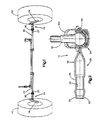
- Fig. 1 there is shown a schematic view of a portion of a vehicle steering system including a ball joint 10 according to a preferred embodiment of the present invention.
- the vehicle steering system comprises a steerable wheel 12 with a steering arm 14, a tie rod 15, and the ball joint 10 connecting the steering arm 14 with the tie rod 15.
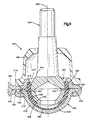
- the ball joint 10 comprises a housing 16.
- the housing 16 is formed from a stamped metal blank which is folded about a centrally located hinge portion 18 to bring opposite housing sections 20 and 22 into overlying relationship.
- the ball joint 10 has a socket end 24 and a sleeve end 25.
- the sleeve end 25 has internal threads 26 for engagement with external threads 27 on the tie rod 15.
- a nut 30 holds the tie rod 15 in place within the sleeve end 25 as shown in Fig. 1.
- the sleeve end 25 of the ball joint 10 can be formed specifically in accordance with the invention disclosed in co-pending Patent Application Serial No. 444,563, filed December 1, 1989, entitled “Turnbuckle Assembly", assigned to the present assignee.
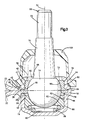
- the socket end 24 of the ball joint 10 has an axis 32, and comprises overlying cup-shaped portions of the two housing sections 20 and 22.
- the first housing section 20 includes a first cup-shaped portion 34 having a first edge surface 38, a circular stud opening surface 39, and a generally cylindrical inner surface 40 extending from the stud opening surface 39 to the first edge surface 38.
- the inner surface 40 includes an annular shoulder 41 spaced axially from the first edge surface 38 by a relatively narrow cylindrical surface portion 42.
- the second housing section 22 includes a second cup-shaped portion 44 with a second edge surface 48 and a closed end 50.
- a generally cylindrical inner surface 52 of the second cup-shaped portion 44 similarly includes an annular shoulder 54 spaced axially from the second edge surface 48 by a relatively narrow cylindrical surface portion 56.
- Placement of the first housing section 20 in a closed position overlying the second housing section 22 defines a chamber 60 with a generally cylindrical inner surface 62.
- the inner surfaces 40 and 52 of the first and second cup-shaped portions 34 and 44 define axial sections of the chamber surface 62 on opposite sides of a seam 64 which is, in turn, defined by the overlying edge surfaces 38 and 48 of the overlying cup-shaped portions 34 and 44.
- the overlying edge surfaces 38 and 48 are in abutting relationship.
- the opposing annular shoulders 41 and 54, and the associated cylindrical surface portions 42 and 56 define a recess 65 in the chamber surface 62.
- the seam 64 borders the recess 65, and extends circumferentially between opposite ends of the foldable hinge portion 18.
- the ball joint 10 further comprises a stud 66 having a generally spherical ball end 68 and a partially tapered shank 70.
- the stud 66 has a centered position in which the shank 70 is coaxial with the housing axis 32, and has threads 72 at the shank 70 for connection to the steering arm 14 as shown in Fig. 1.
- the ball end 68 has a nearly complete spherical surface 74, and is supported in the housing 16 to rotate about the axis 32 as well as to swing through a clearance between the shank 70 and the stud opening surface 39.
- a generally annular rigid support seat member 75 has a first end surface 76 defining a first open end of the support seat member 75, and a second end surface 78 defining a second open end.
- the support seat member also has a radially inner bearing seat surface 80, and a radially outer surface 82.
- the bearing seat surface 80 extends around and slidably engages the spherical surface 74 of the ball end 68, and the radially outer surface 82 has a contour adapted to register with the contour of the chamber surface 62.
- the radially outer surface 82 defines a circular flange 84 which is closely received within the recess 65.
- the flange 84 extends circumferentially adjacent to the seam 64, and axially traverses the seam 64. Preferably, the flange 84 extends radially into contact with the cylindrical surface portions 42 and 56.
- the support seat member 75 isolates the seam 64 from the chamber 60 to seal the chamber surface 62. A liquid lubricant contained within the chamber 60 is blocked from leaking out of the sectional housing 16 through the seam 64. Furthermore, the support seat member 75 strengthens the sectional housing 16 by providing an internal support for the housing sections 20 and 22.
- the support seat member 75 is preferably formed of a rigid metal material such as steel.
- a plastic wear take-up seat 90 has an annular bearing seat surface 92 slidably engaging the surface 74 of the ball end 68, and is axially shiftable in the second cup-shaped portion 44 of the housing 16.
- a coil spring 96 biases the wear take-up seat 90 away from the closed end 50 toward the support seat member 75 to hold the ball end 68 firmly seated in the housing 16.
- a generally conical, flexible elastomeric boot seal 100 extends between the tapered shank 70 and the first housing section 20 to cover the stud opening defined by the surface 39.
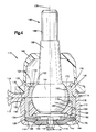
- the ball joint 110 comprises a housing 112.
- the housing 112 is formed from a stamped metal blank which is folded about a centrally located hinge portion 114 to bring two opposite housing sections 116 and 118 into overlying relationship.
- the first housing section 116 includes a first cup-shaped portion 120.
- the first cup-shaped portion 120 includes a first edge surface 122, a frustoconical stud opening surface 124, and an inner surface 126 extending from the stud opening surface 124 to the first edge surface 122.
- the second housing section 118 includes a second cup-shaped portion 128.
- the second cup-shaped portion 128 includes a second edge surface 130, a surface 132 defining an opening, and an inner surface 134 extending between the surface 132 and the second edge surface 130.
- the inner surface 134 includes an annular shoulder 136.
- the first and second cup-shaped portions 120 and 128 of the housing 112 have a common axis 138.
- Placement of the first housing section 116 in a closed position overlying the second housing section 118 moves the first and second cup-shaped portions 120 and 128 into adjacent positions with the first and second edge surfaces 122 and 130 in overlying, abutting relationship to define a seam 140.
- the adjacent cup-shaped portions 120 and 128 of the housing 112 define a chamber 142 with a surface 144 which is defined by the axially adjacent inner surfaces 126 and 134.
- the seam 140 extends circumferentially around the surface 144 of the chamber 142 between the ends of the hinge portion 114 of the housing 112.
- the ball joint 110 also includes a grease plug 150 having an inside surface 152 and an outside surface 154.
- the grease plug 150 is received within the opening defined by the surface 132, with the outside surface 154 of the grease plug 150 resting on the annular shoulder 136.
- the grease plug 150 includes a threaded grease opening 156 which is closable by a threaded plug 158.
- a stud 160 is received in the housing 112.
- the stud 160 comprises a generally spherical ball end 162 having a nearly complete spherical surface 164, and a partially tapered shank 166 extending axially from the ball end 162.
- the shank 166 has threads 168 for connection of the shank 166 to a steering arm of a vehicle steering assembly.
- the stud 160 is supported in the housing 112 to rotate about the axis 138 and to swing through a clearance between the shank 166 and the stud opening surface 124.
- a generally cylindrical support seat member 170 is received in the housing 112.
- the support seat member 170 has a first end surface 172 adjacent to the stud opening surface 124, and a second end surface 174 abutting against the inside surface 152 of the grease plug 150.
- the support seat member 170 also has an outer surface 176 with a contour adapted to register with the contour of the chamber surface 144, and an inner surface 178.
- the inner surface 178 of the support seat member 170 includes a cylindrical portion 180, and a spherically contoured bearing portion 182 which slidably engages the spherical surface 164 of the ball end 162.
- the support seat member 170 blocks leakage of a lubricant through the seam 140, and is preferably formed of steel in order to maximize the underlying structural support which the support seat member 170 provides for the sectional structure of the housing 112.
- the ball joint 110 also includes a plastic wear take-up seat 184.
- the plastic wear take-up seat 184 has an annular bearing seat surface 185 engaging the spherical surface 164 of the ball end 162, and a radially outer cylindrical surface 186 which is flush with the cylindrical portion 180 of the inner surface 178 of the steel support seat member 170.
- the plastic wear take-up seat 184 is axially shiftable within the housing 112, and is biased toward the first cup-shaped portion 120 of the housing 112 by a coil spring 188 in order to hold the ball end 162 of the stud 160 firmly seated in the housing 112.
- a boot seal 190 is received on the socket assembly 110 to provide a seal in a conventional manner.
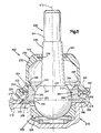
- a ball joint 200 includes a housing 210 which comprises an axis 212, two housing sections 214 and 216, and a hinge portion 218 connecting the two housing sections 214 and 216.
- the two housing sections 214 and 216 are in overlying relationship to define a chamber 220 within the housing 210.
- the first housing section 214 has a cylindrical surface 222 defining an opening, an outer housing surface 223, and a first inner surface 224.
- the second housing section 216 is cup-shaped, and includes a second inner surface 226 surrounded by an annular edge surface 228.
- the first inner surface 224 of the first housing section 214 and the annular edge surface 228 of the second housing section 216 converge as shown in Fig. 5 to define a seam 230 and a circumferentially extending recess 232.
- the seam 230 extends around the chamber 220 bordering the recess 232 between the ends of the hinge portion 218 of the housing 210.
- a stud 236 is received in the housing 210.
- the stud 236 comprises a shank 238, and a ball end 240 having a spherically contoured surface 242.
- the stud 236 has threads 244 at the shank 238 for connection of the stud 236 to a steering arm of a vehicle steering assembly.
- a generally annular support seat member 250 preferably formed of steel, is received in the housing 210.
- the support seat member 250 has a radially inner bearing seat surface 252 slidably engaged with the spherically contoured surface 242 of the ball end 240, and has a radially outer surface 254.
- the radially outer surface 254 includes a cylindrical portion 256, and a portion 258 which defines a circular flange 260.
- the flange 260 extends radially into the recess 232 to hold the support seat member 250 firmly in place in the housing' 210, and extends axially between the converging surfaces 224 and 228 to block leakage of a lubricant toward the seam 230.
- An outer portion 262 of the support seat member 250 extends axially from the opening defined by the cylindrical surface 222 of the housing 210.
- the outer portion 262 includes a frustoconical surface 264 and an annular outer surface 266.
- the frustoconical surface 264 of the support seat member 250 serves as a stop surface to limit swinging movement of the stud 236.
- the outer surfaces 254 and 266 of the support seat member 250, and the surfaces 222 and 223 of the housing 210, serve as mounting surfaces for a boot seal 270.
- the boot seal 270 comprises an elastomeric sleeve 272 having an axis 273, a first end portion 274, and a second end portion 276.
- the first end portion 274 of the sleeve 272 has a surface 278 which defines a circular opening receivable over the shank 238 of the stud 236.
- a split ring 280 is received within the first end portion 274 of the sleeve 272 to clamp the surface 278 against the shank 238.
- the second end portion 276 of the sleeve 272 has an inner surface 282 and an outer surface 284.
- the inner and outer surfaces 282 and 284 of the second end portion 276 of the sleeve 270 have contours adapted to register with the contours of the mounting surfaces on the housing 210 and the support seat member 250.
- the inner surface 282 has a portion 286 adapted to register with the annular outer surface 266 of the support seat member 250, and has a portion 288 adapted to register with the cylindrical outer surface portion 256 of the support seat member 250.
- the outer surface 284 of the sleeve 272 has a portion 290 adapted to register with the cylindrical housing surface 222, and has a portion 292 adapted to register with the outer housing surface 223.
- the second end portion 276 of the sleeve 272 includes a metal retainer ring 300.
- the retainer ring 300 has an axis 302, arcuate segments 304, and groups of radial projections 306 spaced apart by the arcuate segments 304.
- the radial projections 306 are resiliently flexible axially, whereas the arcuate segments 304 are rigid.
- the radial projections 306 have end surfaces 308 with a curvature defining a first inside radius R1 of the retainer ring 300, and the arcuate segments 304 have edge surfaces 310 with a curvature defining a second inside radius R2 of the retainer ring 300.
- the second inside radius R2 is slightly greater than the first inside radius R1, and is approximately equal to the diameter of the cylindrical portion 256 of the radially outer surface 254 of the support seat member 250.
- the retainer ring 300 is embedded within the second end portion 276 of the sleeve 272.
- the radial projections 306 are forced to flex axially into positions wherein the corners 312 of the radial projections 306 are locked against the cylindrical outer surface portion 256 of the support seat member 250 to retain the boot seal 270 in place.
- a ball joint 400 in accordance with yet another alternate embodiment of the invention is shown in Fig. 8.
- the ball joint 400 includes a housing 402.
- the housing 402 has an axis 403, first and second housing sections 404 and 406 which are joined by a hinge portion 408, and a third housing section 410 which is clamped to the first and second housing sections 404 and 406.
- the first housing section 404 includes a frustoconical surface 412 defining a stud opening, an annular edge surface 414, and a first inner surface 416 extending between the frustoconical surface 412 and the edge surface 414.
- the second housing section 406 includes a cylindrical surface 418 defining an opening, and a second inner surface 420.
- the edge surface 414 of the first housing section 404 and the second inner surface 420 of the second housing section 406 converge as shown in Fig. 8 to define an outer seam 422 bordering a circumferentially extending recess 424.
- the outer seam 422 extends around the recess 424 between the ends of the hinge portion 408.
- the third housing section 410 includes a spherically inclined portion 430 and a circular flange portion 432.
- the flange portion 432 is received in the recess 424, whereby the third housing section is firmly clamped to the first and second housing sections 404 and 406.
- the spherically inclined portion 430 of the third housing section 410 has a third inner surface 434 which slopes radially outwardly to the flange portion 432.
- the third inner surface 434 and the first inner surface 416 thus converge to define an inner seam 440, and together define a chamber 442 within the housing 402.
- the inner seam 440 extends entirely around the chamber 442.
- a rigid support seat member 450 is received in the chamber 442.
- the support seat member 450 has a radially inner bering seat surface 452 which is slidably engaged with the surface of a ball end 454 of a stud 456.
- the support seat member 450 also has a radially outer surface 458 which is firmly engaged with the housing 402.
- the radially outer surface 458 traverses the inner seam 440 axially, and extends circumferentially along the length of the inner seam 440.
- the support seat member 450 thereby blocks leakage of a lubricant outwardly through the inner seam 440.
- the ball joint 400 further includes a centering piece 460 for holding the support seat member 450 firmly in place in the chamber 442. As shown in Fig. 8, the components of the ball joint 400 thus far described are formed of a plastic material.
- a boot seal 462 is received on the first housing section 404 in a conventional manner.
Landscapes
- Engineering & Computer Science (AREA)
- General Engineering & Computer Science (AREA)
- Mechanical Engineering (AREA)
- Chemical & Material Sciences (AREA)
- Combustion & Propulsion (AREA)
- Transportation (AREA)
- Physics & Mathematics (AREA)
- Geometry (AREA)
- Pivots And Pivotal Connections (AREA)
Applications Claiming Priority (2)
| Application Number | Priority Date | Filing Date | Title |
|---|---|---|---|
| US524129 | 1983-08-17 | ||
| US07/524,129 US5066160A (en) | 1990-05-14 | 1990-05-14 | Ball joint |
Publications (3)
| Publication Number | Publication Date |
|---|---|
| EP0459644A2 true EP0459644A2 (fr) | 1991-12-04 |
| EP0459644A3 EP0459644A3 (fr) | 1991-12-11 |
| EP0459644B1 EP0459644B1 (fr) | 1994-12-07 |
Family
ID=24087882
Family Applications (1)
| Application Number | Title | Priority Date | Filing Date |
|---|---|---|---|
| EP91304210A Expired - Lifetime EP0459644B1 (fr) | 1990-05-14 | 1991-05-10 | Articulation à rotule |
Country Status (5)
| Country | Link |
|---|---|
| US (1) | US5066160A (fr) |
| EP (1) | EP0459644B1 (fr) |
| JP (1) | JP2750028B2 (fr) |
| DE (1) | DE69105624T2 (fr) |
| ES (1) | ES2067862T3 (fr) |
Cited By (4)
| Publication number | Priority date | Publication date | Assignee | Title |
|---|---|---|---|---|
| EP0658469A1 (fr) * | 1993-12-17 | 1995-06-21 | Chrysler Corporation | Joint à rotule |
| EP0779442A1 (fr) * | 1995-12-12 | 1997-06-18 | Trw Inc. | Ensemble d'articulation |
| EP0635648B1 (fr) * | 1993-07-22 | 1998-05-13 | Dana Corporation | Dispositif d'articulation à rotule |
| WO2026073755A1 (fr) * | 2024-10-03 | 2026-04-09 | Zf Friedrichshafen Ag | Bague de serrage à auto-centrage et soufflet d'étanchéité doté d'une telle bague de serrage |
Families Citing this family (28)
| Publication number | Priority date | Publication date | Assignee | Title |
|---|---|---|---|---|
| US5066160A (en) | 1990-05-14 | 1991-11-19 | Trw Inc. | Ball joint |
| US5286131A (en) * | 1992-08-17 | 1994-02-15 | Trw Inc. | Ball joint and method of assembly |
| DE4301303C1 (de) * | 1993-01-20 | 1994-08-18 | Lemfoerder Metallwaren Ag | Kugelgelenk |
| US5672024A (en) * | 1995-06-02 | 1997-09-30 | Dana Corporation | Prepackaged ball joint |
| US5568930A (en) * | 1995-08-25 | 1996-10-29 | Trw Inc. | Joint assembly |
| US5765844A (en) * | 1995-11-06 | 1998-06-16 | Trw Inc. | Linkage assembly |
| US6010271A (en) * | 1996-02-01 | 2000-01-04 | Trw Inc. | Joint assembly |
| KR20000002051A (ko) * | 1998-06-16 | 2000-01-15 | 오상수 | 볼 조인트 |
| US6343889B1 (en) | 1998-09-28 | 2002-02-05 | Odyssey X-Treme Technologies, Inc. | Split-socket ball joint |
| DE19938770A1 (de) * | 1999-08-16 | 2001-04-12 | Trw Fahrwerksyst Gmbh & Co | Kugelgelenk mit Lagerschale |
| US6568870B2 (en) | 2001-08-08 | 2003-05-27 | Urresko, S.A. De C.V. | Steering tie rod end |
| DE10249847B4 (de) * | 2002-10-25 | 2008-08-28 | Mavig Gmbh | Gelenkige Aufhängung |
| US7644500B2 (en) * | 2006-01-17 | 2010-01-12 | Federal-Mogul World Wide, Inc. | Method of setting the pre-load for a ball socket joint |
| US8342769B2 (en) * | 2009-02-13 | 2013-01-01 | Elterman James J | Pivot socket with cartridge bearing and vehicle steering linkage therewith |
| US8851785B1 (en) * | 2009-11-17 | 2014-10-07 | Trw Automotive U.S. Llc | Ball joint |
| KR20110063164A (ko) * | 2009-12-04 | 2011-06-10 | 현대자동차주식회사 | 서스펜션 암 |
| KR101252066B1 (ko) * | 2011-07-08 | 2013-04-12 | (주) 에스문 | 볼힌지 구조 |
| US20130223919A1 (en) * | 2012-02-23 | 2013-08-29 | Jürgen Brecht | Connection device for adjustable connection of medical equipment to a stationary fixture |
| WO2014011470A1 (fr) * | 2012-07-12 | 2014-01-16 | Borgwarner Inc. | Dispositif tendeur d'embout et embout autoréglable |
| US10184511B2 (en) * | 2013-01-11 | 2019-01-22 | United Technologies Corporation | Linkage with spherical or journal bearing assembly |
| US9801719B2 (en) | 2014-08-15 | 2017-10-31 | Edwards Lifesciences Corporation | Annulus rings with suture clips |
| US9440676B1 (en) * | 2015-08-05 | 2016-09-13 | Christopher E. Sparr | Tie rod assembly with integrated safety tip |
| US10473147B2 (en) * | 2016-03-15 | 2019-11-12 | Federal-Mogul Motorparts Llc | Socket assembly and method of making a socket assembly |
| US10584737B2 (en) * | 2016-03-15 | 2020-03-10 | Federal-Mogul Motorparts Llc | Compression loaded ball socket assembly |
| US10371195B2 (en) * | 2016-06-01 | 2019-08-06 | Federal-Mogul Motorparts Llc | Socket assembly and method of making a socket assembly |
| US10294983B2 (en) * | 2016-06-10 | 2019-05-21 | Federal-Mogul Motorparts Llc | Socket assembly and method of making a socket assembly |
| CN111873732B (zh) * | 2020-07-14 | 2021-09-17 | 中车大同电力机车有限公司 | 麦弗逊式独立悬挂装置及车辆 |
| KR20250146457A (ko) * | 2024-04-01 | 2025-10-13 | 현대모비스 주식회사 | 차량용 현가 장치 |
Family Cites Families (27)
| Publication number | Priority date | Publication date | Assignee | Title |
|---|---|---|---|---|
| DE1071509B (fr) * | 1959-12-17 | |||
| US1898100A (en) * | 1929-12-09 | 1933-02-21 | O & S Bearing Company | Permanent connecting unit and method of forming same |
| US2420621A (en) * | 1944-12-02 | 1947-05-13 | Thompson Prod Inc | Socket assembly |
| GB829998A (en) * | 1955-09-22 | 1960-03-09 | Viktor Langen | A ball and socket joint for a front wheel suspension in motor vehicles |
| US2976068A (en) * | 1956-09-11 | 1961-03-21 | Ford Motor Co | Ball joint |
| US3084960A (en) * | 1961-02-20 | 1963-04-09 | Lifka Charles | Rain-tight connector |
| US3259408A (en) * | 1961-05-03 | 1966-07-05 | Trw Inc | Ball joint |
| US3290074A (en) * | 1964-03-03 | 1966-12-06 | Barmatic Machines Inc | Ball joint assemblies |
| GB1177973A (en) * | 1967-09-13 | 1970-01-14 | Automotive Prod Co Ltd | Improvements in and relating to Ball and Socket Joints |
| US3547474A (en) * | 1969-07-15 | 1970-12-15 | Trw Inc | Boot seal |
| AT325431B (de) * | 1972-01-05 | 1975-10-27 | Joern Raoul Dipl Ing | Kugelgelenk |
| US3846032A (en) * | 1972-06-17 | 1974-11-05 | Hojitsu Kogyo Co Ltd | Ball joint device |
| JPS5098180U (fr) * | 1974-01-14 | 1975-08-15 | ||
| DE2420241A1 (de) * | 1974-04-26 | 1975-11-06 | Bosch Gmbh Robert | Antriebsgestaengeteil |
| GB1490874A (en) * | 1974-12-23 | 1977-11-02 | Automotive Prod Co Ltd | Pivot joints |
| US4059361A (en) * | 1975-07-07 | 1977-11-22 | Ford Motor Company | Tie rod end |
| US3988818A (en) * | 1975-07-07 | 1976-11-02 | Ford Motor Company | Tie rod end |
| JPS559736Y2 (fr) * | 1978-02-07 | 1980-03-03 | ||
| JPS58129321U (ja) * | 1982-02-25 | 1983-09-01 | トヨタ自動車株式会社 | ボ−ルジヨイント |
| FR2560140B1 (fr) * | 1984-02-28 | 1991-09-13 | Redele Jean | Embout a rotule pour direction de vehicule automobile |
| JPH0725658B2 (ja) * | 1984-07-27 | 1995-03-22 | ライオン株式会社 | 口腔用組成物 |
| US4712940A (en) * | 1985-04-23 | 1987-12-15 | Trw Inc. | Joint assembly |
| US4695182A (en) * | 1986-01-02 | 1987-09-22 | Trw Inc. | Ball joint with mechanical interlock |
| US4725159A (en) * | 1986-07-16 | 1988-02-16 | Trw Inc. | Bearing for a joint |
| US4887486A (en) * | 1988-02-22 | 1989-12-19 | Trw, Inc. | Linkage component |
| US4890949A (en) * | 1988-04-07 | 1990-01-02 | Trw Inc. | Tie rod end |
| US5066160A (en) | 1990-05-14 | 1991-11-19 | Trw Inc. | Ball joint |
-
1990
- 1990-05-14 US US07/524,129 patent/US5066160A/en not_active Expired - Lifetime
-
1991
- 1991-05-10 DE DE69105624T patent/DE69105624T2/de not_active Expired - Fee Related
- 1991-05-10 ES ES91304210T patent/ES2067862T3/es not_active Expired - Lifetime
- 1991-05-10 EP EP91304210A patent/EP0459644B1/fr not_active Expired - Lifetime
- 1991-05-14 JP JP3228228A patent/JP2750028B2/ja not_active Expired - Fee Related
Cited By (6)
| Publication number | Priority date | Publication date | Assignee | Title |
|---|---|---|---|---|
| EP0635648B1 (fr) * | 1993-07-22 | 1998-05-13 | Dana Corporation | Dispositif d'articulation à rotule |
| EP0658469A1 (fr) * | 1993-12-17 | 1995-06-21 | Chrysler Corporation | Joint à rotule |
| US5538275A (en) * | 1993-12-17 | 1996-07-23 | Chrysler Corporation | Ball joint seal with heat shield |
| EP0779442A1 (fr) * | 1995-12-12 | 1997-06-18 | Trw Inc. | Ensemble d'articulation |
| US5697723A (en) * | 1995-12-12 | 1997-12-16 | Trw Inc. | Joint assembly |
| WO2026073755A1 (fr) * | 2024-10-03 | 2026-04-09 | Zf Friedrichshafen Ag | Bague de serrage à auto-centrage et soufflet d'étanchéité doté d'une telle bague de serrage |
Also Published As
| Publication number | Publication date |
|---|---|
| DE69105624D1 (de) | 1995-01-19 |
| US5066160A (en) | 1991-11-19 |
| JP2750028B2 (ja) | 1998-05-13 |
| ES2067862T3 (es) | 1995-04-01 |
| DE69105624T2 (de) | 1995-04-20 |
| EP0459644B1 (fr) | 1994-12-07 |
| EP0459644A3 (fr) | 1991-12-11 |
| JPH0658320A (ja) | 1994-03-01 |
Similar Documents
| Publication | Publication Date | Title |
|---|---|---|
| US5066160A (en) | Ball joint | |
| US6042294A (en) | Ball joint having rotational and axial movement | |
| US6010272A (en) | Ball joint with two-piece bearing and spring | |
| US3381987A (en) | Double wall seal for articulated joints | |
| US5931597A (en) | Ball joint | |
| US5782573A (en) | Ball-and-socket joint with ball retention device | |
| US5876149A (en) | Ball joint | |
| US5653545A (en) | Ball-and-socket joint for motor vehicles | |
| US9925838B2 (en) | Ball joint assembly for a control arm | |
| JPS61500502A (ja) | ハブシ−ルおよび軸スリ−ブ | |
| US2971787A (en) | Ball joint assembly | |
| US11466727B2 (en) | Ball socket assembly, dust boot therefor and method of construction thereof | |
| TWI738887B (zh) | 高傾斜度球形接頭組件 | |
| EP1460289B1 (fr) | Structure pour coupler un joint spherique et un bras | |
| JPH07151140A (ja) | ワイパー用の駆動機構における回転シャフト用ベアリング装置 | |
| KR100351405B1 (ko) | 자동차용 조향장치의 유니버셜 조인트 | |
| US5022779A (en) | Ball joint | |
| US5927891A (en) | Boot seal for a ball and socket joint | |
| US7090425B2 (en) | Balljoint | |
| CA3035735A1 (fr) | Stabilisateur et son procede d'assemblage | |
| US10954995B2 (en) | Socket assembly and method of making | |
| JP2004316908A (ja) | 自在継手 | |
| US3279833A (en) | Ball joint and seal assembly | |
| EP0075414B1 (fr) | Articulation à rotule | |
| US4538935A (en) | Ball and socket joint, particularly for heavily loaded joint linkages in motor vehicles |
Legal Events
| Date | Code | Title | Description |
|---|---|---|---|
| PUAI | Public reference made under article 153(3) epc to a published international application that has entered the european phase |
Free format text: ORIGINAL CODE: 0009012 |
|
| PUAL | Search report despatched |
Free format text: ORIGINAL CODE: 0009013 |
|
| AK | Designated contracting states |
Kind code of ref document: A2 Designated state(s): DE ES FR GB IT |
|
| AK | Designated contracting states |
Kind code of ref document: A3 Designated state(s): DE ES FR GB IT |
|
| 17P | Request for examination filed |
Effective date: 19911219 |
|
| 17Q | First examination report despatched |
Effective date: 19930125 |
|
| GRAA | (expected) grant |
Free format text: ORIGINAL CODE: 0009210 |
|
| AK | Designated contracting states |
Kind code of ref document: B1 Designated state(s): DE ES FR GB IT |
|
| REF | Corresponds to: |
Ref document number: 69105624 Country of ref document: DE Date of ref document: 19950119 |
|
| ITF | It: translation for a ep patent filed | ||
| ET | Fr: translation filed | ||
| REG | Reference to a national code |
Ref country code: ES Ref legal event code: FG2A Ref document number: 2067862 Country of ref document: ES Kind code of ref document: T3 |
|
| PLBE | No opposition filed within time limit |
Free format text: ORIGINAL CODE: 0009261 |
|
| STAA | Information on the status of an ep patent application or granted ep patent |
Free format text: STATUS: NO OPPOSITION FILED WITHIN TIME LIMIT |
|
| 26N | No opposition filed | ||
| REG | Reference to a national code |
Ref country code: GB Ref legal event code: IF02 |
|
| PGFP | Annual fee paid to national office [announced via postgrant information from national office to epo] |
Ref country code: GB Payment date: 20030401 Year of fee payment: 13 |
|
| PGFP | Annual fee paid to national office [announced via postgrant information from national office to epo] |
Ref country code: FR Payment date: 20030505 Year of fee payment: 13 |
|
| PGFP | Annual fee paid to national office [announced via postgrant information from national office to epo] |
Ref country code: ES Payment date: 20030526 Year of fee payment: 13 |
|
| PG25 | Lapsed in a contracting state [announced via postgrant information from national office to epo] |
Ref country code: GB Free format text: LAPSE BECAUSE OF NON-PAYMENT OF DUE FEES Effective date: 20040510 |
|
| PG25 | Lapsed in a contracting state [announced via postgrant information from national office to epo] |
Ref country code: ES Free format text: LAPSE BECAUSE OF NON-PAYMENT OF DUE FEES Effective date: 20040511 |
|
| GBPC | Gb: european patent ceased through non-payment of renewal fee |
Effective date: 20040510 |
|
| PG25 | Lapsed in a contracting state [announced via postgrant information from national office to epo] |
Ref country code: FR Free format text: LAPSE BECAUSE OF NON-PAYMENT OF DUE FEES Effective date: 20050131 |
|
| REG | Reference to a national code |
Ref country code: FR Ref legal event code: ST |
|
| PG25 | Lapsed in a contracting state [announced via postgrant information from national office to epo] |
Ref country code: IT Free format text: LAPSE BECAUSE OF NON-PAYMENT OF DUE FEES;WARNING: LAPSES OF ITALIAN PATENTS WITH EFFECTIVE DATE BEFORE 2007 MAY HAVE OCCURRED AT ANY TIME BEFORE 2007. THE CORRECT EFFECTIVE DATE MAY BE DIFFERENT FROM THE ONE RECORDED. Effective date: 20050510 |
|
| REG | Reference to a national code |
Ref country code: ES Ref legal event code: FD2A Effective date: 20040511 |
|
| PGFP | Annual fee paid to national office [announced via postgrant information from national office to epo] |
Ref country code: DE Payment date: 20070531 Year of fee payment: 17 |
|
| PG25 | Lapsed in a contracting state [announced via postgrant information from national office to epo] |
Ref country code: DE Free format text: LAPSE BECAUSE OF NON-PAYMENT OF DUE FEES Effective date: 20081202 |