EP0459659A1 - Etikettiersystem - Google Patents
Etikettiersystem Download PDFInfo
- Publication number
- EP0459659A1 EP0459659A1 EP91304374A EP91304374A EP0459659A1 EP 0459659 A1 EP0459659 A1 EP 0459659A1 EP 91304374 A EP91304374 A EP 91304374A EP 91304374 A EP91304374 A EP 91304374A EP 0459659 A1 EP0459659 A1 EP 0459659A1
- Authority
- EP
- European Patent Office
- Prior art keywords
- control unit
- radio wave
- unit
- label
- label unit
- Prior art date
- Legal status (The legal status is an assumption and is not a legal conclusion. Google has not performed a legal analysis and makes no representation as to the accuracy of the status listed.)
- Withdrawn
Links
Images


Classifications
-
- G—PHYSICS
- G07—CHECKING-DEVICES
- G07G—REGISTERING THE RECEIPT OF CASH, VALUABLES, OR TOKENS
- G07G1/00—Cash registers
- G07G1/12—Cash registers electronically operated
- G07G1/14—Systems including one or more distant stations co-operating with a central processing unit
- G07G1/145—PLU-management
-
- G—PHYSICS
- G06—COMPUTING OR CALCULATING; COUNTING
- G06K—GRAPHICAL DATA READING; PRESENTATION OF DATA; RECORD CARRIERS; HANDLING RECORD CARRIERS
- G06K17/00—Methods or arrangements for effecting co-operative working between equipments covered by two or more of main groups G06K1/00 - G06K15/00, e.g. automatic card files incorporating conveying and reading operations
-
- G—PHYSICS
- G06—COMPUTING OR CALCULATING; COUNTING
- G06K—GRAPHICAL DATA READING; PRESENTATION OF DATA; RECORD CARRIERS; HANDLING RECORD CARRIERS
- G06K17/00—Methods or arrangements for effecting co-operative working between equipments covered by two or more of main groups G06K1/00 - G06K15/00, e.g. automatic card files incorporating conveying and reading operations
- G06K17/0022—Methods or arrangements for effecting co-operative working between equipments covered by two or more of main groups G06K1/00 - G06K15/00, e.g. automatic card files incorporating conveying and reading operations arrangements or provisions for transferring data to distant stations, e.g. from a sensing device
-
- G—PHYSICS
- G09—EDUCATION; CRYPTOGRAPHY; DISPLAY; ADVERTISING; SEALS
- G09F—DISPLAYING; ADVERTISING; SIGNS; LABELS OR NAME-PLATES; SEALS
- G09F9/00—Indicating arrangements for variable information in which the information is built-up on a support by selection or combination of individual elements
Definitions
- This invention relates to labelling systems, particularly, but not exclusively, labelling systems for use in retail outlets.
- a labelling system comprising: at least one control unit including radio wave transmission means for transmitting information, and radio wave reception means; and at least one label unit including reception means for receiving information from a control unit, display means for displaying at least part of the information received from the control unit, data communication means for communicating data to the or another control unit by reflection of a radio wave transmitted by the control unit, and an antenna, the characteristics of which are varied in response to the data to be communicated such that the received radio wave is reflected and modulated by the antenna.
- the label unit By communicating data back to a control unit by reflecting a radio wave, the label unit does not require a large power supply, for it does not have to generate the radio wave and so can utilise low power batteries, hence allowing the unit to be manufactured cheaply and compactly.
- control unit is provided at a single location although in some circumstances the radio transmitter might be separate from other parts of the control unit. In such cases more than one transmitter per control unit might be appropriate.
- a labelling system in accordance with the invention may employ only one control unit but it may be advantageous to include a plurality of control units in the system, particularly where large coverage is required or where there are obstacles in the transmission and reception paths. Where a plurality of control units are included, it is preferred that they are connected to a common processor means. This may then be used to synchronise transmissions from each control unit, for example, and to report information received from the labelling units to a stock control system, say. However, there could be a plurality of control units which are independent of one another and are not connected in this way.
- control unit Where a plurality of control units are employed, or there are a plurality of transmitters for one control unit, it may be advantageous to arrange that only one transmitter transmits to a particular labelling unit.
- the transmitter physically nearest the labelling unit may be selected or the transmitter which produces the strongest reflected signal used.
- each control unit of a plurality of such units sends information for reception by one label unit. This increase the probability that the information will be correctly received by that label unit. It is preferred that each of a plurality of transmitters transmits the same frequency.
- the label unit includes means for imposing a frequency offset on the reflected radio wave. This enables the reflected signal to be distinguished from the transmitted signal at the control unit so that substantially simultaneous transmission and reception at the control unit may be implemented.
- a label unit is arranged to receive a radio wave from one control unit and reflected to another control unit. Such a bi-static arrangement increases the likelihood of receiving the reflected wave from the label unit and may enable a stronger signal to be reflected from the labelled unit.
- the radio wave reflected by the label may be relayed by a further transmitter separate from the control unit or a passive relay may be used.
- the control unit can comprise a computer including a console for the entry of information and connected to a radio transmitter.
- the label units can be mounted on a shelf where the item is stored and displayed.
- the display means might be a liquid crystal display (L.C.D.), a light emitting diode (L.E.D.) display, or a tactile display employing for instance braille for the benefit of visually handicapped persons.
- the label unit display means preferably includes a liquid crystal display.
- the display means includes a display adapted to communicate data to a bar code reader.
- the display might display a complete bar code or it may be convenient to have a single element display caused to switch between an off and on stage to simulate a sweep of the reader over a complete code.
- the data to be communicated from the label to the control unit can include data verifying that the information had been correctly received and it might also include other data such as a malfunction warning or a battery state warning.
- the verification data might simply be the data transmitted to it by the control unit or a binary digit indicating whether or not the transmission was correctly received.
- the label unit also includes means for checking the data received before replying to the control unit.
- the modulation by the antenna to transmit data to a control unit may be amplitude modulation or phase modulation for example.
- the label unit could include photovoltaic means for at least partly powering the label unit.
- the photovoltaic means may be a solar cell or an array of solar cells which will generate power from lights in the store.
- the label unit includes power storage means such as a primary or secondary cell or battery of such cells, or a high value capacitor which can enable the label unit to operate in darkness when any photovoltaic means will not function. Where a secondary cell or capacitor is used as the electricity storage means, it may conveniently, be charged by the photovoltaic means.
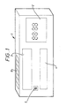
- a label unit 1 has a number of liquid crystal displays 2, 3, 4 and 5.
- a solar cell arrangement 6 On an upper surface is a solar cell arrangement 6.
- Liquid crystal display 2 is a price display, whilst displays 3 and 4 display an item's name and also promotional information such as "Sale Item” or "Special Reduction”.
- Display 5 is a single element L.C.D. for interfacing the label unit 1 to a standard bar code reader.
- the solar cell arrangement 6 generates the power for the label unit 1 from lights in a store in which the unit is positioned.
- Information is transmitted from a control unit 7 as shown in Figure 2 by modulating a transmitted radio frequency signal.
- the information may contain instructions governing operation of the label unit 1 or information to be displayed.
- the transmissions are received by all the label units in the store in a similar manner, each unit has an antenna 8a and a receiver 8b connected to an integrated circuit comprising an I.D. checker 9, a parity checker 10, an information processor 12 and a memory 11.
- the I.D checker 9 checks the transmissions for an identification number which identifies the label unit 1 and denotes that the information is to be displayed by that unit. In response to the correct identification number being transmitted the I.D checker 9 activates the rest of the circuitry, that is, it is brought in to a state of readiness for the information.
- a parity check is performed on the information received, by a parity checker 10, in order to verify that the information is complete by comparison with a check number held in memory 11. If the numbers are in agreement, a processor 12 processes the information and passes it to the memory 11 where it is stored before being displayed by the displays 13.
- the result of the transmission is communicated to the control unit 7 by transmission means 14a, an antenna 14b of which reflects a radio wave transmitted by the control unit 7.
- the radio wave forms a carrier wave which, in this embodiment, is amplitude modulated by varying the characteristics of the antenna 14b by a reflective modulator (not shown), to encode the carrier wave with the result and other verification data.
- the control unit 7 re-transmits information to the label unit 1. After a predetermined number of transmissions are sent without success the control unit 7 reports the existence of a fault.
- Display 5 allows the label unit 1 to communicate with a bar code reader by simulating the sweep of the reader over a bar code in the following manner. Firstly the reader is positioned over the display 5, which is a single element liquid crystal display. The display is caused to switch between reflective and non-reflective states. The light emitted by the reader is therefore alternately reflected and not reflected and a sweep by the reader of a bar code simulated. The information passed in this manner might include the item and its price which would be useful when stocktaking.
- the processor 12 has provision for connection to input and output devices. Suitable input devices could include proximity sensors such as vibration or infra red detectors for detecting the presence of a trolley, vehicle or person. When the presence was detected the label unit 1 might then be activated in order that the information was displayed as a customer was passing. This would be most useful where the power consumption of the displays was high.
- proximity sensors such as vibration or infra red detectors for detecting the presence of a trolley, vehicle or person.
- Another input device could include a customer help button in response to activation of which, the label unit would transmit a message back to the control unit that an assistant should be sent to that location.
- Further sensors could include temperature sensors or smoke detectors for managing the temperature of the store or as a precaution against fire. Again the information derived could be communicated to the control unit.
- Devices that could be connected to the output connection include voice synthesis units which would possibly be of assistance to the visually handicapped or other units that it would be desirable to activate from one control unit.
- the same antenna may be used both for reception and reflection.
- another arrangement in accordance with the invention includes a plurality of control units 15 and 16 two of which are shown, each having a transmitting antenna 17 and 18 respectively and a receiving antenna 19 and 20 respectively.
- the control units 15 and 16 are connected to a processor circuit 21 which in turn is connected via lines 22 to stock control systems for a store.
- the control units of the arrangement partially illustrated in Figure 3 are distributed around a shop floor as shown in Figure 4, where additional control units 23 and 24 are illustrated.
- the system also includes a label unit 25 distributed on a shelves in the store.
- the dotted lines illustrate the respective ranges of the control unit transmitters, which in this arrangement is approximately 10 metres. It can be seen that some of the labelling units 25 fall within the sphere of only one transmitter and in that case, they would be serviced solely by that transmitter. However, there are other label units which are capable of receiving transmissions from a plurality of transmitters. If the line of transmission is blocked, for example, by a passer-by, then there is a good chance that the transmission from a control unit is still received by those label units.
- Figure 5 illustrates one mode of operation of the system shown in Figure 4.
- a label unit 26 is arranged to receive transmissions from one control unit 27 and reflect them to a second control unit 28 located remotely from the first unit. Similarly, transmission from control unit 28 are reflected by the label unit 26 to the control unit 27 for reception.
Landscapes
- Engineering & Computer Science (AREA)
- Physics & Mathematics (AREA)
- General Physics & Mathematics (AREA)
- Theoretical Computer Science (AREA)
- Computer Networks & Wireless Communication (AREA)
- General Engineering & Computer Science (AREA)
- Cash Registers Or Receiving Machines (AREA)
- Control Of Indicators Other Than Cathode Ray Tubes (AREA)
Applications Claiming Priority (2)
| Application Number | Priority Date | Filing Date | Title |
|---|---|---|---|
| GB909011161A GB9011161D0 (en) | 1990-05-18 | 1990-05-18 | Labelling system |
| GB9011161 | 1990-05-18 |
Publications (1)
| Publication Number | Publication Date |
|---|---|
| EP0459659A1 true EP0459659A1 (de) | 1991-12-04 |
Family
ID=10676209
Family Applications (1)
| Application Number | Title | Priority Date | Filing Date |
|---|---|---|---|
| EP91304374A Withdrawn EP0459659A1 (de) | 1990-05-18 | 1991-05-15 | Etikettiersystem |
Country Status (3)
| Country | Link |
|---|---|
| EP (1) | EP0459659A1 (de) |
| CA (1) | CA2042724A1 (de) |
| GB (2) | GB9011161D0 (de) |
Cited By (4)
| Publication number | Priority date | Publication date | Assignee | Title |
|---|---|---|---|---|
| WO1997014107A1 (de) * | 1995-10-13 | 1997-04-17 | Orgalogic Gmbh | Elektronisches preisinformationssystem |
| EP0713196A3 (de) * | 1994-11-15 | 2000-11-08 | NCR International, Inc. | Elektronische Anzeigesystemen |
| WO2007012891A3 (en) * | 2005-07-25 | 2007-06-28 | Siemens Ag | A radio frequency identification interrogator |
| FR2926387A1 (fr) * | 2008-01-14 | 2009-07-17 | Roland Caville | Dispositif de presentation d'une information, notamment sur un produit et/ou un service, equipe d'une alimentation autonome |
Families Citing this family (2)
| Publication number | Priority date | Publication date | Assignee | Title |
|---|---|---|---|---|
| IL114965A (en) * | 1995-08-17 | 2001-01-11 | Eldat Comm Ltd | System and method for providing a store customer with personally associated prices for selected items |
| GB2369918A (en) * | 2000-12-08 | 2002-06-12 | Ncr Int Inc | Electronic price label networks |
Citations (7)
| Publication number | Priority date | Publication date | Assignee | Title |
|---|---|---|---|---|
| WO1983000251A1 (en) * | 1981-07-06 | 1983-01-20 | Motorola Inc | Real time, computer-driven retail pricing display system |
| EP0167072A2 (de) * | 1984-06-30 | 1986-01-08 | Altura Leiden Holding B.V. | Vorrichtung zur Speicherung und Ausgabe von Informationsmengen |
| FR2604315A1 (fr) * | 1986-09-22 | 1988-03-25 | Stevens John | Systemes de telecommunications par radiodiffusion notamment pour l'affichage electronique des prix dans un magasin de vente au detail |
| US4766295A (en) * | 1987-03-02 | 1988-08-23 | H.E. Butt Grocery Company | Electronic pricing display system |
| EP0279627A2 (de) * | 1987-02-17 | 1988-08-24 | Real Time Developments Limited | Übertragungsvorrichtung |
| WO1988006773A1 (en) * | 1987-02-26 | 1988-09-07 | Gabriel Ordonez | Retail display system |
| GB2212965A (en) * | 1987-11-25 | 1989-08-02 | Christos Nicos Theophilou | An electrically operated display ticket |
Family Cites Families (2)
| Publication number | Priority date | Publication date | Assignee | Title |
|---|---|---|---|---|
| US4521677A (en) * | 1983-12-02 | 1985-06-04 | Sarwin Herbert S | Product control system for supermarkets and the like |
| SE8405140L (sv) * | 1984-10-15 | 1985-10-07 | Makoson Ab | Anordning for hyllkantmerkning |
-
1990
- 1990-05-18 GB GB909011161A patent/GB9011161D0/en active Pending
-
1991
- 1991-05-15 EP EP91304374A patent/EP0459659A1/de not_active Withdrawn
- 1991-05-16 CA CA002042724A patent/CA2042724A1/en not_active Abandoned
- 1991-05-16 GB GB9110555A patent/GB2244839A/en not_active Withdrawn
Patent Citations (7)
| Publication number | Priority date | Publication date | Assignee | Title |
|---|---|---|---|---|
| WO1983000251A1 (en) * | 1981-07-06 | 1983-01-20 | Motorola Inc | Real time, computer-driven retail pricing display system |
| EP0167072A2 (de) * | 1984-06-30 | 1986-01-08 | Altura Leiden Holding B.V. | Vorrichtung zur Speicherung und Ausgabe von Informationsmengen |
| FR2604315A1 (fr) * | 1986-09-22 | 1988-03-25 | Stevens John | Systemes de telecommunications par radiodiffusion notamment pour l'affichage electronique des prix dans un magasin de vente au detail |
| EP0279627A2 (de) * | 1987-02-17 | 1988-08-24 | Real Time Developments Limited | Übertragungsvorrichtung |
| WO1988006773A1 (en) * | 1987-02-26 | 1988-09-07 | Gabriel Ordonez | Retail display system |
| US4766295A (en) * | 1987-03-02 | 1988-08-23 | H.E. Butt Grocery Company | Electronic pricing display system |
| GB2212965A (en) * | 1987-11-25 | 1989-08-02 | Christos Nicos Theophilou | An electrically operated display ticket |
Non-Patent Citations (1)
| Title |
|---|
| IBM TECHNICAL DISCLOSURE BULLETIN vol. 26, no. 4, September 1983, NEW YORK, US pages 1865 - 1869; C.S. LANIER ET.AL.: 'Bandwidth usage in peer-to-peer closed rings ' * |
Cited By (4)
| Publication number | Priority date | Publication date | Assignee | Title |
|---|---|---|---|---|
| EP0713196A3 (de) * | 1994-11-15 | 2000-11-08 | NCR International, Inc. | Elektronische Anzeigesystemen |
| WO1997014107A1 (de) * | 1995-10-13 | 1997-04-17 | Orgalogic Gmbh | Elektronisches preisinformationssystem |
| WO2007012891A3 (en) * | 2005-07-25 | 2007-06-28 | Siemens Ag | A radio frequency identification interrogator |
| FR2926387A1 (fr) * | 2008-01-14 | 2009-07-17 | Roland Caville | Dispositif de presentation d'une information, notamment sur un produit et/ou un service, equipe d'une alimentation autonome |
Also Published As
| Publication number | Publication date |
|---|---|
| GB9110555D0 (en) | 1991-07-03 |
| GB9011161D0 (en) | 1990-07-04 |
| CA2042724A1 (en) | 1991-11-19 |
| GB2244839A (en) | 1991-12-11 |
Similar Documents
| Publication | Publication Date | Title |
|---|---|---|
| US4766295A (en) | Electronic pricing display system | |
| KR0146709B1 (ko) | 데이타 전송 시스템 | |
| US5841365A (en) | Method and apparatus for communicating with a product label | |
| US6046682A (en) | Electronic price label including noisemaker and method of locating electronic price labels | |
| US5697061A (en) | Method and apparatus for providing information concerning products, using radio frequency transmissions | |
| US5861817A (en) | System for, and method of, displaying prices on tags in supermarkets | |
| US8896422B2 (en) | Methods, systems, and products for tracking objects | |
| US6736316B2 (en) | Inventory control and indentification method | |
| JP3466188B2 (ja) | 伝送された情報の受領通知の方法及び装置 | |
| EP0790596B1 (de) | Verfahren zum Orten von elektronischen Preisschildern in Verkaufsniederlassungen | |
| AU714367B2 (en) | Method of diagnosing communication problems of electronic price labels | |
| US8517265B2 (en) | Error free method for wireless display tag (WDT) | |
| EP1249804A2 (de) | System und Verfahren zur Anzeige von Artikelinformationen mit elektronischen Schildern | |
| US7178727B2 (en) | Remote controlled separable electronic price tag | |
| EP0889425A1 (de) | Subglobale Adressierung von elektronischen Preisschildern | |
| GB2244839A (en) | Labelling system | |
| RU2669145C2 (ru) | Компоновка, система и способ для уменьшения эффекта помех на радиочастотах в системе электронного ценника | |
| US6724318B2 (en) | Device and method of locating electronic price labels in transaction establishments | |
| US11948040B2 (en) | Electronic price label and electronic price label system | |
| JPH10510938A (ja) | 電子価格インフォメーションシステム | |
| EP0837411A1 (de) | Ferngesteuerte elektronische Anzeigemodule | |
| WO1990014630A1 (en) | Remote electronic information display system | |
| EP0669030B1 (de) | Solarschalter | |
| CN208861408U (zh) | 一种可多配置的智能重力货柜 | |
| US20160321478A1 (en) | Wireless information communicating terminal and device for its updating |
Legal Events
| Date | Code | Title | Description |
|---|---|---|---|
| PUAI | Public reference made under article 153(3) epc to a published international application that has entered the european phase |
Free format text: ORIGINAL CODE: 0009012 |
|
| AK | Designated contracting states |
Kind code of ref document: A1 Designated state(s): AT BE CH DE DK ES FR GR IT LI LU NL SE |
|
| 17P | Request for examination filed |
Effective date: 19920415 |
|
| STAA | Information on the status of an ep patent application or granted ep patent |
Free format text: STATUS: THE APPLICATION HAS BEEN WITHDRAWN |
|
| 18W | Application withdrawn |
Withdrawal date: 19930722 |