EP0459740A1 - Exzenterschneckenpumpe - Google Patents
Exzenterschneckenpumpe Download PDFInfo
- Publication number
- EP0459740A1 EP0459740A1 EP91304784A EP91304784A EP0459740A1 EP 0459740 A1 EP0459740 A1 EP 0459740A1 EP 91304784 A EP91304784 A EP 91304784A EP 91304784 A EP91304784 A EP 91304784A EP 0459740 A1 EP0459740 A1 EP 0459740A1
- Authority
- EP
- European Patent Office
- Prior art keywords
- stator
- helical gear
- rotor
- rubber
- gear formation
- Prior art date
- Legal status (The legal status is an assumption and is not a legal conclusion. Google has not performed a legal analysis and makes no representation as to the accuracy of the status listed.)
- Withdrawn
Links
- 230000015572 biosynthetic process Effects 0.000 claims description 19
- 238000000576 coating method Methods 0.000 claims description 13
- 239000011248 coating agent Substances 0.000 claims description 12
- PXHVJJICTQNCMI-UHFFFAOYSA-N Nickel Chemical compound [Ni] PXHVJJICTQNCMI-UHFFFAOYSA-N 0.000 claims description 6
- 229920003051 synthetic elastomer Polymers 0.000 claims description 5
- 239000005061 synthetic rubber Substances 0.000 claims description 5
- 238000005660 chlorination reaction Methods 0.000 claims description 3
- BHEPBYXIRTUNPN-UHFFFAOYSA-N hydridophosphorus(.) (triplet) Chemical compound [PH] BHEPBYXIRTUNPN-UHFFFAOYSA-N 0.000 claims description 3
- 229910052759 nickel Inorganic materials 0.000 claims description 3
- 239000002184 metal Substances 0.000 claims 1
- 229910052751 metal Inorganic materials 0.000 claims 1
- 238000010438 heat treatment Methods 0.000 abstract description 7
- 230000000694 effects Effects 0.000 abstract description 4
- 229920001971 elastomer Polymers 0.000 description 23
- 239000005060 rubber Substances 0.000 description 21
- 239000012530 fluid Substances 0.000 description 5
- 239000013536 elastomeric material Substances 0.000 description 4
- 239000011324 bead Substances 0.000 description 3
- 238000005461 lubrication Methods 0.000 description 3
- 230000000704 physical effect Effects 0.000 description 3
- 238000010276 construction Methods 0.000 description 2
- 239000000806 elastomer Substances 0.000 description 2
- 238000000034 method Methods 0.000 description 2
- 238000000465 moulding Methods 0.000 description 2
- 230000000750 progressive effect Effects 0.000 description 2
- 238000002474 experimental method Methods 0.000 description 1
- 239000004810 polytetrafluoroethylene Substances 0.000 description 1
- 229920001343 polytetrafluoroethylene Polymers 0.000 description 1
- 238000005096 rolling process Methods 0.000 description 1
- 238000007789 sealing Methods 0.000 description 1
Images

Classifications
-
- F—MECHANICAL ENGINEERING; LIGHTING; HEATING; WEAPONS; BLASTING
- F04—POSITIVE - DISPLACEMENT MACHINES FOR LIQUIDS; PUMPS FOR LIQUIDS OR ELASTIC FLUIDS
- F04C—ROTARY-PISTON, OR OSCILLATING-PISTON, POSITIVE-DISPLACEMENT MACHINES FOR LIQUIDS; ROTARY-PISTON, OR OSCILLATING-PISTON, POSITIVE-DISPLACEMENT PUMPS
- F04C2/00—Rotary-piston machines or pumps
- F04C2/08—Rotary-piston machines or pumps of intermeshing-engagement type, i.e. with engagement of co-operating members similar to that of toothed gearing
- F04C2/10—Rotary-piston machines or pumps of intermeshing-engagement type, i.e. with engagement of co-operating members similar to that of toothed gearing of internal-axis type with the outer member having more teeth or tooth-equivalents, e.g. rollers, than the inner member
- F04C2/107—Rotary-piston machines or pumps of intermeshing-engagement type, i.e. with engagement of co-operating members similar to that of toothed gearing of internal-axis type with the outer member having more teeth or tooth-equivalents, e.g. rollers, than the inner member with helical teeth
- F04C2/1071—Rotary-piston machines or pumps of intermeshing-engagement type, i.e. with engagement of co-operating members similar to that of toothed gearing of internal-axis type with the outer member having more teeth or tooth-equivalents, e.g. rollers, than the inner member with helical teeth the inner and outer member having a different number of threads and one of the two being made of elastic materials, e.g. Moineau type
- F04C2/1073—Rotary-piston machines or pumps of intermeshing-engagement type, i.e. with engagement of co-operating members similar to that of toothed gearing of internal-axis type with the outer member having more teeth or tooth-equivalents, e.g. rollers, than the inner member with helical teeth the inner and outer member having a different number of threads and one of the two being made of elastic materials, e.g. Moineau type where one member is stationary while the other member rotates and orbits
- F04C2/1075—Construction of the stationary member
-
- F—MECHANICAL ENGINEERING; LIGHTING; HEATING; WEAPONS; BLASTING
- F05—INDEXING SCHEMES RELATING TO ENGINES OR PUMPS IN VARIOUS SUBCLASSES OF CLASSES F01-F04
- F05C—INDEXING SCHEME RELATING TO MATERIALS, MATERIAL PROPERTIES OR MATERIAL CHARACTERISTICS FOR MACHINES, ENGINES OR PUMPS OTHER THAN NON-POSITIVE-DISPLACEMENT MACHINES OR ENGINES
- F05C2225/00—Synthetic polymers, e.g. plastics; Rubber
- F05C2225/04—PTFE [PolyTetraFluorEthylene]
Definitions
- Helical gear pumps also known as progressive cavity pumps
- a stator formed of an elastomeric material, usually synthetic rubber, comprising a stator body having a female helical gear formation of n starts defining major and minor diameters, and a rotor rotatable within the female helical gear formation of the stator, the rotor having a male helical gear formation of n ⁇ 1 starts.
- stator involves a barrel, which is usually generally cylindrical, and the elastomeric material of the stator is molded into this barrel.
- the lubrication is normally the pumped fluid.
- the lubrication is normally the pumped fluid.
- there must be an interference fit between the rotor and the stator and the stator must be formed of an elastomeric material. This combination results in a build-up of heat during normal pump operation due to hysteresis, produced in the elastomer.
- the pump As long as the pump is operated within its design parameters, then there is lubrication produced by the fluid being pumped and, the heat build-up remains within acceptable limits. However, from time to time, the pump is caused to run dry due to a failure of the supply of the pumped fluid. The heat generated due to frictional heating of the rubber stator very quickly exceeds acceptable levels, causing the elastomer to revert to its uncured state and to disintegrate.
- the time taken for the stator to reach unacceptable levels is two minutes from the onset of dry running. This short time period means that the various protection devices used to detect dry running and to switch off the pump are not entirely reliable, because they have insufficient time in which to react to the dry run condition.
- a helical gear pump stator comprising a stator body having a female helical gear formation thereon defining major and minor diameters, said stator body being formed of an elastomeric material, the wall thickness of the stator body being substantially constant, the surface of the female helical gear formation being subjected to an anti-friction coating.
- the anti-friction coating may be achieved by chlorination of the synthetic rubber.
- the design of the present invention in which the wall thickness of the stator is constant and the surface of the helical gear formation is formed with an anti-friction coating largely overcomes these problems insofar as the constant rubber thickness around the stator section means that the physical properties at each position around the section are identical and the interference between the rotor and stator, at the minor diameter, can be reduced as compared with that found with the conventional design. It is believed that this is due to the thinner section of the rubber present at the minor diameter which is stiffer than for the conventional design of stator.
- the invention also provides a helical gear pump including a stator according to the invention, the helical gear formation having n starts and a rotor rotatable within said female helical gear formation, the rotor having a cooperating male helical gear formation of n ⁇ 1 starts, the surface of the rotor having a friction reducing coating, such as a nickel phosphorous coating impregnated with polytetraflorethylene.
- the helical gear pump illustrated therein comprises a main housing 10 having an inlet 12, the housing having attached to it the helical gear pump itself indicated by the general reference numeral 14, an outlet 16 being provided at the far end.
- the pump 14 includes a barrel 18 having molded therein a constant wall thickness stator 20 formed with a female helical gear formation 22 having 2 starts.
- a rotor 24 is caused to rotate and orbit within the stator by means of a flexible drive shaft 26 passing through the housing 10.
- the outer surface of the rotor has a male helical gear formation of the same pitch as the gear formation 22 but having a single start.
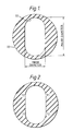
- FIG. 1 there is illustrated therein a conventional stator construction which has the female helical gear formation 22 therein. It will be observed that the outer surface 23 of this stator is circular being located in a barrel (not shown) of cylindrical shape. This produces a varying rubber thickness, the thickness being far greater at the minor diameter than at the major diameter indicated. During normal operation of such a conventional stator pump, a maximum temperature of the stator occurs at the minor diameter, as seen in Figure 2.
- the temperature T1 is slightly lower than the maximum temperature T2 on the other side. This temperature distribution is caused it is believed, by the mechanism of the rotor rolling along the straight sides of the stator cross-section and forming a bead of rubber along the straight sides of the stator slot. At the location of the temperature T1, the bead of rubber is quite small as the rotor has only traversed a short distance along that side of the slot. By the time it reaches the end of the slot, the bead of rubber will have increased in size having been swept over a longer distance and therefore will generate more heat due to hysteresis effects.
- the interference between the rotor and the stator, at the minor diameter, can be reduced as compared with that encountered on the conventional stator design.This is due to the thinner section of rubber present at the minor diameter which is stiffer than for the conventional design of stator.
- the surface of the rubber may be treated with a friction reducing coating, and this may be achieved, for example, by treating the surface with a chlorination process.
- the rotor is provided also with a coating to reduce the friction, such as that sold under the trade name 'Niflor' which is a PTFE impregnated nickel phosphorous. This reduces the frictional co-efficient of the rotor surface.
- the temperature of the rubber in the constant wall stator is found to be much lower than for conventional designs of stator.
- the lower temperature occurs due to the thinner, and hence stiffer, sections of rubber generating less heat due to hysteresis. This effect is especially noticeable at the stator minor diameter where there is a significant reduction in temperature as compared with a conventional stator.
- the thinner rubber in the constant wall stator of the invention has a reduced insulating effect and hence contributes to the lower stator temperature.
Landscapes
- Engineering & Computer Science (AREA)
- Mechanical Engineering (AREA)
- General Engineering & Computer Science (AREA)
- Rotary Pumps (AREA)
- Details And Applications Of Rotary Liquid Pumps (AREA)
Applications Claiming Priority (2)
| Application Number | Priority Date | Filing Date | Title |
|---|---|---|---|
| GB9012134 | 1990-05-31 | ||
| GB9012134A GB2244517B (en) | 1990-05-31 | 1990-05-31 | Helical gear pump and stator |
Publications (1)
| Publication Number | Publication Date |
|---|---|
| EP0459740A1 true EP0459740A1 (de) | 1991-12-04 |
Family
ID=10676833
Family Applications (1)
| Application Number | Title | Priority Date | Filing Date |
|---|---|---|---|
| EP91304784A Withdrawn EP0459740A1 (de) | 1990-05-31 | 1991-05-28 | Exzenterschneckenpumpe |
Country Status (6)
| Country | Link |
|---|---|
| US (1) | US5145343A (de) |
| EP (1) | EP0459740A1 (de) |
| AU (1) | AU643789B2 (de) |
| FI (1) | FI912608L (de) |
| GB (1) | GB2244517B (de) |
| NO (1) | NO912087L (de) |
Cited By (3)
| Publication number | Priority date | Publication date | Assignee | Title |
|---|---|---|---|---|
| EP0616128A1 (de) * | 1993-02-15 | 1994-09-21 | Sanden Corporation | Trägervorrichtung einer Schiefscheibe und Herstellungsverfahren |
| GB2305470A (en) * | 1995-09-25 | 1997-04-09 | Heishin Sobi Kk | Eccentric screw pump |
| WO2004036043A1 (en) * | 2002-10-21 | 2004-04-29 | Noetic Engineering Inc. | Stator of a moineau-pump |
Families Citing this family (19)
| Publication number | Priority date | Publication date | Assignee | Title |
|---|---|---|---|---|
| US5611397A (en) * | 1994-02-14 | 1997-03-18 | Wood; Steven M. | Reverse Moineau motor and centrifugal pump assembly for producing fluids from a well |
| US6183226B1 (en) | 1986-04-24 | 2001-02-06 | Steven M. Wood | Progressive cavity motors using composite materials |
| US5759019A (en) * | 1994-02-14 | 1998-06-02 | Steven M. Wood | Progressive cavity pumps using composite materials |
| US5832604A (en) * | 1995-09-08 | 1998-11-10 | Hydro-Drill, Inc. | Method of manufacturing segmented stators for helical gear pumps and motors |
| DE19804259A1 (de) * | 1998-02-04 | 1999-08-12 | Artemis Kautschuk Kunststoff | Elastomerstator für Exzenterschneckenpumpen |
| DE19821867A1 (de) * | 1998-05-15 | 1999-11-18 | Artemis Kautschuk Kunststoff | Nach dem Moineau-Prinzip arbeitende Maschine, insbesondere Bohrmotor für Tiefbohrungen |
| US6309195B1 (en) * | 1998-06-05 | 2001-10-30 | Halliburton Energy Services, Inc. | Internally profiled stator tube |
| FR2794498B1 (fr) * | 1999-06-07 | 2001-06-29 | Inst Francais Du Petrole | Pompe a cavites progressantes a stator composite et son procede de fabrication |
| US6358027B1 (en) | 2000-06-23 | 2002-03-19 | Weatherford/Lamb, Inc. | Adjustable fit progressive cavity pump/motor apparatus and method |
| US6457958B1 (en) | 2001-03-27 | 2002-10-01 | Weatherford/Lamb, Inc. | Self compensating adjustable fit progressing cavity pump for oil-well applications with varying temperatures |
| US6604921B1 (en) | 2002-01-24 | 2003-08-12 | Schlumberger Technology Corporation | Optimized liner thickness for positive displacement drilling motors |
| US6604922B1 (en) | 2002-03-14 | 2003-08-12 | Schlumberger Technology Corporation | Optimized fiber reinforced liner material for positive displacement drilling motors |
| CN101512046B (zh) | 2007-01-24 | 2011-08-10 | 哈利伯顿能源服务公司 | 用于螺杆装置的电铸定子管 |
| CA2696117A1 (en) * | 2007-08-15 | 2009-02-19 | Moyno, Inc. | Progressing cavity pump with heat management system |
| US8182252B2 (en) * | 2007-10-30 | 2012-05-22 | Moyno, Inc. | Progressing cavity pump with split stator |
| US8215014B2 (en) | 2007-10-31 | 2012-07-10 | Moyno, Inc. | Method for making a stator |
| US20150078943A1 (en) * | 2013-09-16 | 2015-03-19 | Baker Hughes Incorporated | Tunable Progressive Cavity Pump |
| FR3081519B1 (fr) * | 2018-05-23 | 2020-05-29 | Pcm Technologies | Element de stator d'une pompe a cavites progressives et pompe a cavites progressives |
| JP7138382B1 (ja) * | 2022-01-18 | 2022-09-16 | 兵神装備株式会社 | 一軸偏心ねじポンプ |
Citations (4)
| Publication number | Priority date | Publication date | Assignee | Title |
|---|---|---|---|---|
| DE2713468A1 (de) * | 1977-03-26 | 1978-09-28 | Allweiler Ag | Stator fuer exzenterschneckenpumpen |
| FR2487017A1 (fr) * | 1980-07-17 | 1982-01-22 | Femmechanika | Stator pour pompe a vis simple |
| EP0209099A1 (de) * | 1985-07-17 | 1987-01-21 | Netzsch-Mohnopumpen GmbH | Stator für Exzenterschneckenpumpen |
| GB2184785A (en) * | 1985-12-27 | 1987-07-01 | Hughes Tool Co | Gear mechanism, especially constituting a moineau-type pump or motor |
Family Cites Families (10)
| Publication number | Priority date | Publication date | Assignee | Title |
|---|---|---|---|---|
| US2527673A (en) * | 1947-02-28 | 1950-10-31 | Robbins & Myers | Internal helical gear pump |
| US3084631A (en) * | 1962-01-17 | 1963-04-09 | Robbins & Myers | Helical gear pump with stator compression |
| US3499389A (en) * | 1967-04-19 | 1970-03-10 | Seeberger Kg | Worm pump |
| GB1220848A (en) * | 1968-06-05 | 1971-01-27 | Mono Pumps Ltd | Rotary pump or motor with an eccentrically rotating rotor |
| DE1703602A1 (de) * | 1968-06-15 | 1972-04-20 | Seeberger Kg Maschinen & Gerae | Schneckenpumpe |
| DE2722623A1 (de) * | 1976-05-21 | 1977-12-08 | Mono Pumps Ltd | Staender fuer exzenterschneckenpumpen oder -motoren, sowie herstellungsverfahren hierfuer |
| DE3229446A1 (de) * | 1982-08-06 | 1984-02-09 | Resch, Maschinen- und Gerätebau GmbH, 8266 Töging | Pumpenstator |
| DE3576844D1 (de) * | 1984-12-12 | 1990-05-03 | Robert A Barr | Wellenfoermige pumpenanlage. |
| US4948432A (en) * | 1988-11-04 | 1990-08-14 | Pacific Alloy Castings, Inc. | Method for manufacturing a rotor for use in a progressive cavity pump |
| DE4006339C2 (de) * | 1990-03-01 | 1994-08-04 | Gd Anker Gmbh & Co Kg | Stator für eine Exzenterschneckenpumpe |
-
1990
- 1990-05-31 GB GB9012134A patent/GB2244517B/en not_active Expired - Fee Related
-
1991
- 1991-05-28 EP EP91304784A patent/EP0459740A1/de not_active Withdrawn
- 1991-05-28 AU AU77341/91A patent/AU643789B2/en not_active Ceased
- 1991-05-30 FI FI912608A patent/FI912608L/fi not_active Application Discontinuation
- 1991-05-30 NO NO91912087A patent/NO912087L/no unknown
- 1991-05-31 US US07/707,125 patent/US5145343A/en not_active Expired - Fee Related
Patent Citations (4)
| Publication number | Priority date | Publication date | Assignee | Title |
|---|---|---|---|---|
| DE2713468A1 (de) * | 1977-03-26 | 1978-09-28 | Allweiler Ag | Stator fuer exzenterschneckenpumpen |
| FR2487017A1 (fr) * | 1980-07-17 | 1982-01-22 | Femmechanika | Stator pour pompe a vis simple |
| EP0209099A1 (de) * | 1985-07-17 | 1987-01-21 | Netzsch-Mohnopumpen GmbH | Stator für Exzenterschneckenpumpen |
| GB2184785A (en) * | 1985-12-27 | 1987-07-01 | Hughes Tool Co | Gear mechanism, especially constituting a moineau-type pump or motor |
Cited By (5)
| Publication number | Priority date | Publication date | Assignee | Title |
|---|---|---|---|---|
| EP0616128A1 (de) * | 1993-02-15 | 1994-09-21 | Sanden Corporation | Trägervorrichtung einer Schiefscheibe und Herstellungsverfahren |
| GB2305470A (en) * | 1995-09-25 | 1997-04-09 | Heishin Sobi Kk | Eccentric screw pump |
| GB2305470B (en) * | 1995-09-25 | 1999-03-31 | Heishin Sobi Kk | Uniaxial eccentric screw pump |
| WO2004036043A1 (en) * | 2002-10-21 | 2004-04-29 | Noetic Engineering Inc. | Stator of a moineau-pump |
| US7442019B2 (en) | 2002-10-21 | 2008-10-28 | Noetic Engineering Inc. | Stator of a moineau-pump |
Also Published As
| Publication number | Publication date |
|---|---|
| FI912608A7 (fi) | 1991-12-01 |
| FI912608A0 (fi) | 1991-05-30 |
| GB2244517A (en) | 1991-12-04 |
| US5145343A (en) | 1992-09-08 |
| GB9012134D0 (en) | 1990-07-18 |
| GB2244517B (en) | 1994-05-04 |
| AU643789B2 (en) | 1993-11-25 |
| NO912087D0 (no) | 1991-05-30 |
| FI912608L (fi) | 1991-12-01 |
| NO912087L (no) | 1991-12-02 |
| AU7734191A (en) | 1991-12-05 |
Similar Documents
| Publication | Publication Date | Title |
|---|---|---|
| US5145343A (en) | Helical gear pump and stator with constant rubber wall thickness | |
| US3139035A (en) | Cavity pump mechanism | |
| US4104009A (en) | Screw pump stators | |
| US3481156A (en) | Power transmission assembly | |
| US5358390A (en) | Eccentric screw pump | |
| US2833224A (en) | Rotary pumps | |
| GB2352008A (en) | Progressive cavity pump stator | |
| BRPI0707208B1 (pt) | Dispositivo e aparelho de cavidade progressiva | |
| US20160084085A1 (en) | Stator for a feed pump | |
| EP1988288A1 (de) | Moineau-Pumpe | |
| US3071314A (en) | Screw compressor seal | |
| KR20110018287A (ko) | 유체 주입식 스크루 압축기 요소 | |
| US2161374A (en) | Motor pump or electric generator | |
| CN114593053A (zh) | 螺杆压缩机和空调系统 | |
| US4013388A (en) | Support means for floating rotary ring member | |
| US2899902A (en) | Rotary pump impeller | |
| KR100311239B1 (ko) | 오일펌프로터 | |
| EP0657649A1 (de) | Rotor und biegsame Antriebswelle Einheit | |
| KR0167638B1 (ko) | 무급유식 스크류 유체기계 | |
| EP0965756A3 (de) | Schraubenpumpe | |
| US4875827A (en) | Fluid pump and method for making the same | |
| EP0071587B1 (de) | Verfahren zur Behandlung von mit einer Dichtlippe versehenen Abdichtungsringen in einem chemischen Bad | |
| EP0882891B1 (de) | Exzenterschneckenpumpe | |
| GB1067014A (en) | Improvements in helical gear pumps | |
| US9511473B2 (en) | Hose end clean-up fixture |
Legal Events
| Date | Code | Title | Description |
|---|---|---|---|
| PUAI | Public reference made under article 153(3) epc to a published international application that has entered the european phase |
Free format text: ORIGINAL CODE: 0009012 |
|
| AK | Designated contracting states |
Kind code of ref document: A1 Designated state(s): AT BE CH DE DK ES FR GB GR IT LI LU NL SE |
|
| 17P | Request for examination filed |
Effective date: 19920519 |
|
| 17Q | First examination report despatched |
Effective date: 19930601 |
|
| STAA | Information on the status of an ep patent application or granted ep patent |
Free format text: STATUS: THE APPLICATION HAS BEEN WITHDRAWN |
|
| 18W | Application withdrawn |
Withdrawal date: 19940124 |