EP0459810A2 - Method and apparatus for the production of hot direct reduced iron - Google Patents
Method and apparatus for the production of hot direct reduced iron Download PDFInfo
- Publication number
- EP0459810A2 EP0459810A2 EP91304909A EP91304909A EP0459810A2 EP 0459810 A2 EP0459810 A2 EP 0459810A2 EP 91304909 A EP91304909 A EP 91304909A EP 91304909 A EP91304909 A EP 91304909A EP 0459810 A2 EP0459810 A2 EP 0459810A2
- Authority
- EP
- European Patent Office
- Prior art keywords
- hot
- zone
- reduction
- reducing gas
- reactor
- Prior art date
- Legal status (The legal status is an assumption and is not a legal conclusion. Google has not performed a legal analysis and makes no representation as to the accuracy of the status listed.)
- Granted
Links
Images
Classifications
-
- C—CHEMISTRY; METALLURGY
- C21—METALLURGY OF IRON
- C21B—MANUFACTURE OF IRON OR STEEL
- C21B13/00—Making spongy iron or liquid steel, by direct processes
- C21B13/02—Making spongy iron or liquid steel, by direct processes in shaft furnaces
-
- C—CHEMISTRY; METALLURGY
- C21—METALLURGY OF IRON
- C21B—MANUFACTURE OF IRON OR STEEL
- C21B2100/00—Handling of exhaust gases produced during the manufacture of iron or steel
- C21B2100/20—Increasing the gas reduction potential of recycled exhaust gases
- C21B2100/22—Increasing the gas reduction potential of recycled exhaust gases by reforming
-
- C—CHEMISTRY; METALLURGY
- C21—METALLURGY OF IRON
- C21B—MANUFACTURE OF IRON OR STEEL
- C21B2100/00—Handling of exhaust gases produced during the manufacture of iron or steel
- C21B2100/20—Increasing the gas reduction potential of recycled exhaust gases
- C21B2100/28—Increasing the gas reduction potential of recycled exhaust gases by separation
- C21B2100/282—Increasing the gas reduction potential of recycled exhaust gases by separation of carbon dioxide
-
- C—CHEMISTRY; METALLURGY
- C21—METALLURGY OF IRON
- C21B—MANUFACTURE OF IRON OR STEEL
- C21B2100/00—Handling of exhaust gases produced during the manufacture of iron or steel
- C21B2100/40—Gas purification of exhaust gases to be recirculated or used in other metallurgical processes
- C21B2100/42—Sulphur removal
-
- C—CHEMISTRY; METALLURGY
- C21—METALLURGY OF IRON
- C21B—MANUFACTURE OF IRON OR STEEL
- C21B2100/00—Handling of exhaust gases produced during the manufacture of iron or steel
- C21B2100/40—Gas purification of exhaust gases to be recirculated or used in other metallurgical processes
- C21B2100/44—Removing particles, e.g. by scrubbing, dedusting
-
- C—CHEMISTRY; METALLURGY
- C21—METALLURGY OF IRON
- C21B—MANUFACTURE OF IRON OR STEEL
- C21B2100/00—Handling of exhaust gases produced during the manufacture of iron or steel
- C21B2100/60—Process control or energy utilisation in the manufacture of iron or steel
- C21B2100/64—Controlling the physical properties of the gas, e.g. pressure or temperature
-
- C—CHEMISTRY; METALLURGY
- C21—METALLURGY OF IRON
- C21B—MANUFACTURE OF IRON OR STEEL
- C21B2100/00—Handling of exhaust gases produced during the manufacture of iron or steel
- C21B2100/60—Process control or energy utilisation in the manufacture of iron or steel
- C21B2100/66—Heat exchange
-
- Y—GENERAL TAGGING OF NEW TECHNOLOGICAL DEVELOPMENTS; GENERAL TAGGING OF CROSS-SECTIONAL TECHNOLOGIES SPANNING OVER SEVERAL SECTIONS OF THE IPC; TECHNICAL SUBJECTS COVERED BY FORMER USPC CROSS-REFERENCE ART COLLECTIONS [XRACs] AND DIGESTS
- Y02—TECHNOLOGIES OR APPLICATIONS FOR MITIGATION OR ADAPTATION AGAINST CLIMATE CHANGE
- Y02P—CLIMATE CHANGE MITIGATION TECHNOLOGIES IN THE PRODUCTION OR PROCESSING OF GOODS
- Y02P10/00—Technologies related to metal processing
- Y02P10/10—Reduction of greenhouse gas [GHG] emissions
- Y02P10/122—Reduction of greenhouse gas [GHG] emissions by capturing or storing CO2
-
- Y—GENERAL TAGGING OF NEW TECHNOLOGICAL DEVELOPMENTS; GENERAL TAGGING OF CROSS-SECTIONAL TECHNOLOGIES SPANNING OVER SEVERAL SECTIONS OF THE IPC; TECHNICAL SUBJECTS COVERED BY FORMER USPC CROSS-REFERENCE ART COLLECTIONS [XRACs] AND DIGESTS
- Y02—TECHNOLOGIES OR APPLICATIONS FOR MITIGATION OR ADAPTATION AGAINST CLIMATE CHANGE
- Y02P—CLIMATE CHANGE MITIGATION TECHNOLOGIES IN THE PRODUCTION OR PROCESSING OF GOODS
- Y02P10/00—Technologies related to metal processing
- Y02P10/10—Reduction of greenhouse gas [GHG] emissions
- Y02P10/134—Reduction of greenhouse gas [GHG] emissions by avoiding CO2, e.g. using hydrogen
Definitions
- This invention relates to a method and apparatus for the gaseous reduction of iron ores in moving bed vertical reduction reactors to directly reduce the ores into sponge iron product which product is hot discharged and which invention is particularly useful for briquetting, for direct introduction of the still-hot product into electric arc furnaces, or the like.
- Sponge iron produced in an apparatus and by a process of this type is disclosed in Beggs et al. U.S. Pat. No. 4,188,022 and Beggs et al. divisional U.S. Pat. No. 4,251,267 wherein iron oxide pellets or other particulate iron ore feed are charged to a vertical shaft furnace having an upper portion defining a reduction zone wherein a moving burden of particles is formed, and through which a hot reducing gas flows upwardly in countercurrent relationship to the movement of the burden, and a bottom portion extending into a hopper, which latter forms a gas disengaging plenum through which a co-current downwardly flowing sealing hot inert gas is disengaged from the descending pellets.
- the seal gas pressure is sufficient to prevent downflow of reducing gas leakage into the lower portion of the furnace, the amount of reducing gas leakage is kept to a minimum.
- the seal gas is preferably a gas having a high nitrogen content, such as the product of combustion containing no free oxygen.
- the principal problem to which that patent is directed is to prevent leakage to the atmosphere of highly combustible and toxic furnace gas from the furnace discharge outlet.
- the patent teaches that the mere use of valves or locks have been tried without success in hot discharge direct reduction furnaces, because of their tendency to become bound or stuck because of the softness and stickiness of the hot reduced iron product which usually causes such valves to leak.
- a hot briquetting machine is coupled to the furnace discharge, it is isolated from the highly flammable gases maintained at relatively high pressure in the reduction furnace by means of the inert seal gas system at the lower end of the furnace, which is intended to insure that the gases present at the furnace discharge are non-flammable despite the character of the gases present within the reduction furnace.
- That patent relies on the use of a hot inert gas which has to be circulated downwardly through the burden to avoid the leakage of the reducing gases.
- Such method and apparatus has the disadvantage that the capital investment is increased because of the ancillary equipment needed to maintain a flow of hot inert gas.
- Sanzenbacher in U.S. Pat. No. 4,536,213 teaches use of natural gas and/or process gas containing significant amounts of higher hydrocarbons as a source for the reducing gas in a similar process and apparatus for the production of sponge iron in a moving bed vertical reduction reactor.
- the natural/process gas is exposed first to the hot descending burden, which acts as a catalyst to crack the higher hydrocarbons, prior to separating, cleaning, and passing such gas through the reformer.
- the gas moves through the reactor only upwardly in the reducing zone countercurrent to the descending hot burden.
- the natural/process gas flows downwardly in a co-current direction with the descending burden in an intermediate portion of the reactor, below the reducing zone.
- the natural/process gas is heated.
- gas is withdrawn and the burden is subsequently cooled by an upflow countercurrent of cooling gas to discharge the burden cold.
- the present invention avoids this cooling effect.
- the shaft furnace has three zones, (A) a gasification and initial reduction zone at the uppermost portion, (B) a second or final reduction zone, and (C) a third cooling and carburizing zone.
- the fuel is gasified by a controlled introduction of oxygen, steam and regenerated top gas and the conditions are controlled to produce CO and H2 diluted with CO2 and steam, while preheating and initiating reduction of the iron ore.
- the ore, fuel, and gases descend co-currently into a second or final reduction zone (B), wherein hot hydrogen-enriched reducing gases are introduced in the middle of the (B) zone.
- Off gases are removed from the upper portion and from the bottom of the second zone (B), cooled, purified of dust and carbon dioxide and, if necessary, of sulfur.
- a portion of the purified gases is mixed with air and burned to produce hot steam and power and to extract oxygen from air.
- the remaining purified gases are divided into two portions, one portion is enriched with H2 and together with hot steam is introduced into the middle of the second zone (B). This flows both upwardly (countercurrent) and downwardly (co-current) through the descending burden.
- the other portion of the remaining purified gases is cooled and dehumidified and introduced into the third zone (C) near the bottom of the furnace above and below a grate for cooling and carburizing.
- the sponge iron from the second zone enters the third cooling and carburizing zone (C), where it descends counter-currently to the rising dehumidified gases which cool and carburize the sponge iron. Finally the sponge iron is discharged cold.
- Celada et al in patent no. 3,816,102 shows a split flow of hot reducing gas in the reduction zone of a moving bed vertical shaft furnace for the production of sponge iron (where there is the usual counter-current flow in the upper part of the reducing zone and a co-current descending flow of reducing gas relative to the descending burden of ore in the lower portion of the reducing zone).
- this patent disclosed a cooling zone and teaches cold discharge of the burden.
- Price-Falcon et al in Patent No. 4,793,856 teach a process for the production of sponge iron where the usual upward counter-current flow of hot reducing gas in the reduction zone of a moving bed vertical shaft reactor is supplemented by a downward co-current flow of cooling gas along the walls of the reactor (to reduce the tendency of the burden to agglomerate and stick to the walls, thus permitting the reduction reaction to proceed at a higher than normal overall temperature thus resulting in more efficient operation).
- the counter-current flow is not only a cooling flow, but the reactor has a cooling zone, and cold discharge of the burden is taught.
- the present invention provides a method and apparatus for the gaseous reduction of iron ores in moving bed vertical reduction reactors into a highly metallized sponge iron product which is hot discharged.
- the reduction reactor has two zones an upper or reduction zone and a lower or discharge zone.
- the ore is charged to the top portion of the reduction reactor wherein it forms a bed which descends by gravity and is discharged by means of a suitable discharge valve.
- the reduction of iron ore mainly takes place while the ore flows downwardly in the reduction zone by means of a stream of hot reducing gas, largely composed of carbon monoxide and hydrogen.
- the reducing gas is fed to the reduction reactor at the bottom portion of the reduction zone and thereafter is divided into two streams, one upwardly flowing stream which performs the reduction counter-currently to the ores in the upper portion of the shaft furnace, and a downwardly flowing stream which flows co-currently with the bed and compensates for the heat lost during the passage of the bed through the lower or discharge zone wherein the bed is modified or carburized and thus maintaining the average bulk temperature of the product at a suitable high level.
- Such high levels range from 450 to 1100 degrees C, and more typically above 650 degrees for briquetting and in the 850 to 1000 degree C range for metallurgical processing of the product (particularly 900 to 970 degrees C for sponge iron product).
- the split flow is on the order of 90% upward and 10% downward.
- the downward flow can be modified as to flow rate, etc. so as to control carbonization of the sponge iron.
- hot particles are discharged from the bed and conveyed typically without further modification directly to electric arc furnaces or the like to be melted or be hot briquetted by means of a briquetting machine coupled to the reduction reactor.
- the advantages of the split flow can be similarly achieved by feeding two separate flows of gas to the reactor in the region where the reduction zone and discharge zone meet, with the first such flow being reducing gas for upflow through the reduction zone and with the other such flow being a modified reducing gas, inert gas, natural gas, other carbonizing gas, or any other different hot gas appropriate for flowing through the discharge zone.
- the present invention surprisingly can be used in maintaining the average bulk hot temperature of the particles discharged from the reactor while simultaneously cooling the outer particles in the discharge zone (to prevent sticking of hot sponge iron as taught by MacKay et al. U.S. Patent No. 4,725,309 issued February 16, 1988, the content of which is incorporated herein by reference). Even more surprising is the present inventors' combination of the present invention with the disclosure in the aforementioned Patent No. 4,793,856 whereby a separate cooling co-current flow occurs along the walls of the reactor (but in the discharge zone, rather than in an intermediate zone) while simultaneously a hot co-current flow passes through the core of the discharge zone including bulk of the particles in such zone. This serves to prevent sticking, while maintaining the bulk average temperature.
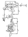
- the numeral 10 designates a vertical shaft furnace having an upper reduction zone 12. Iron ore particles to be reduced enter to the top portion of the reactor 10 through feed pipes 14 wherein the descending bed of particles 15 are contacted with a counter-currently flowing stream 17 of hot reducing gas in the reduction zone 12 to convert said ore to sponge iron.
- the sponge iron product is hot discharged from the reduction reactor through a discharge pipe 16 and may be densified by means of a conventional briquetting machine 18 or may be conveyed to a remote location to be melted in an electric arc furnace, an induction furnace or other similar furnace used in the art.
- the reducing gas can be produced by any known manner, for example in a catalytic reformer 20 by converting a mixture of steam entering through pipe 22, heat exchanger 24 and pipe 26 and natural gas passing through pipe 28, into a gas largely composed of carbon monoxide and hydrogen.
- the reduced gas can be produced within the reduction reactor 10 by the method disclosed in U.S. Pat. No. 4,528,030.
- the thus formed reducing gas is dewatered in heat exchanger 30 and conducted through pipes 32 and 34 to heater 36 and fed through inlet gas pipe 38 to the bottom portion of the reduction zone 12.
- a portion of natural gas may be diverted through pipe 40 and mixed thereafter with the reformed gas flowing in pipe 32.
- the incoming stream of reducing gas is divided into two portions 17 and 41.
- a first portion 17 flows upwardly counter-current to and reducing the descending bed of ore to metallic iron.
- the spent reducing gases leave the reduction reactor through exit pipe 42 and pipe 44 to cooling and dewatering quench cooler 46.
- a portion of the cooled and dewatered gases is conducted from pipe 48 and to vent pipe 50 to be used in another location or to be disposed of and the remaining major portion is fed as a recycled gas successively through a compressor 52, pipe 54, carbon dioxide removal unit 56, pipe 34, and on to heater 36 wherein the recycled gas is heated preferably to a temperature of 900°C to 950°C.
- the heated recycled gas is thence fed through pipe 38 to the bottom portion of the reduction zone 12.
- a second portion 41 of the reducing gas flows downward co-currently to the bed of particles to provide the heat lost during the passage of the bed through the discharge zone 58 of the reactor. Since the reducing gas is upgraded prior to its introduction to the reduction reactor, certain controlled amounts of a hydrocarbon containing gas can be added (e.g. via pipe 40) as a portion of the make up. Therefore, the downwardly flowing reducing gas may modify or carburize the descending bed to a predetermined degree.
- split flow 17 and 41 in the broader aspects of the invention as previously indicated, can be similarly achieved by feeding two separate flows of gas to the reactor; flow 17 via pipe 38 as before and flow 41 by separate pipe-and-plenum 70.
- Wall 60 may be surrounded by a plurality of insulating heat-exchanging jackets (not shown, such as those disclosed in U.S. Pat. No. 4,725,309) adapted selectively to control or stop the amount of cooling fluid circulating therethrough so that the temperature of the wall 60 is maintained at desired levels to prevent sticking at the walls for assuring a uniform and smooth flow of the bed of particles through this discharge zone of the furnace.
- the peripheral cooling along the walls 60 may be accomplished as disclosed in Patent No. 4,793,856 by a compatible cool co-current gas flow introduced at pipe-and-plenum 72 (which cool gas flows down along the walls 60 to the discharge plenum 62 and which is separate from the hot co-current gas flow 41 through the core of the discharge zone). Though somewhat more complex, this has the advantage of further independent control of the discharge zone relative to the reduction zone.
- a portion of the recycled gas may be diverted through pipe 66 to provide an upflow of cleaned and cooled gas to and through the discharge zone 58 (by closing valve 68) in case a cool discharge may be temporarily be needed or otherwise preferred (for example, during maintenance of the electric arc furnace, or other device to which the hot discharge is normally fed, it being difficult and potentially hazardous openly to store hot sponge iron).
- the present invention provides an effective method and apparatus for producing sponge iron at a temperature suitable for melting or briquetting.
- the invention uses a portion of the same reducing gas which performs the direct reduction of the bed of iron ore to compensate for heat lost during the passage of the bed along the discharge zone of the reactor (minimizing in this way the capital and operation costs by avoiding the need of extra equipment and the use of different gases to provide such heat).
- the product sponge iron has the same good characteristics of the product obtained by any other process with hot discharge.
Landscapes
- Engineering & Computer Science (AREA)
- Chemical & Material Sciences (AREA)
- Manufacturing & Machinery (AREA)
- Materials Engineering (AREA)
- Metallurgy (AREA)
- Organic Chemistry (AREA)
- Manufacture Of Iron (AREA)
- Manufacture And Refinement Of Metals (AREA)
Abstract
Description
- This invention relates to a method and apparatus for the gaseous reduction of iron ores in moving bed vertical reduction reactors to directly reduce the ores into sponge iron product which product is hot discharged and which invention is particularly useful for briquetting, for direct introduction of the still-hot product into electric arc furnaces, or the like.
- Typically the production of sponge metal in moving bed vertical reduction reactors involves the reduction of pebble-sized particles or lumps of metal oxides, ores or the like which descend downwardly through a reduction zone counter to a suitable upwardly flowing stream of hot reducing gas, largely composed of carbon monoxide and hydrogen at temperatures on the order of 850°C to 1100°C and for iron oxide preferably 900°C to 1000°, and modifying or carburizing the reduced metal oxides in a lower zone of the reduction reactor and discharging and conveying the hot metallized product without further modification directly to electric arc furnaces or the like by means of any appropriate conveying means, or hot briquetting the discharged product by means of a briquetting machine directly coupled to the reduction reactor.
- Sponge iron produced in an apparatus and by a process of this type is disclosed in Beggs et al. U.S. Pat. No. 4,188,022 and Beggs et al. divisional U.S. Pat. No. 4,251,267 wherein iron oxide pellets or other particulate iron ore feed are charged to a vertical shaft furnace having an upper portion defining a reduction zone wherein a moving burden of particles is formed, and through which a hot reducing gas flows upwardly in countercurrent relationship to the movement of the burden, and a bottom portion extending into a hopper, which latter forms a gas disengaging plenum through which a co-current downwardly flowing sealing hot inert gas is disengaged from the descending pellets. Since the seal gas pressure is sufficient to prevent downflow of reducing gas leakage into the lower portion of the furnace, the amount of reducing gas leakage is kept to a minimum. Thus the gas leakage from the furnace through the furnace discharge pipe is principally recirculated seal gas containing only small amounts of CO and H₂ reducing gas. The seal gas is preferably a gas having a high nitrogen content, such as the product of combustion containing no free oxygen.
- The principal problem to which that patent is directed is to prevent leakage to the atmosphere of highly combustible and toxic furnace gas from the furnace discharge outlet. The patent teaches that the mere use of valves or locks have been tried without success in hot discharge direct reduction furnaces, because of their tendency to become bound or stuck because of the softness and stickiness of the hot reduced iron product which usually causes such valves to leak. Although a hot briquetting machine is coupled to the furnace discharge, it is isolated from the highly flammable gases maintained at relatively high pressure in the reduction furnace by means of the inert seal gas system at the lower end of the furnace, which is intended to insure that the gases present at the furnace discharge are non-flammable despite the character of the gases present within the reduction furnace.
- That patent relies on the use of a hot inert gas which has to be circulated downwardly through the burden to avoid the leakage of the reducing gases. Such method and apparatus has the disadvantage that the capital investment is increased because of the ancillary equipment needed to maintain a flow of hot inert gas.
- See also U.S. Patents 4,734,128 and 4,834,792 for two other references showing hot discharge of sponge iron from a moving bed direct reduction reactor (with addition of natural gas to either the discharge zone or to the reducing zone, for control of carburization). No co-current flows are taught relative to the descending moving bed.
- Sanzenbacher in U.S. Pat. No. 4,536,213 teaches use of natural gas and/or process gas containing significant amounts of higher hydrocarbons as a source for the reducing gas in a similar process and apparatus for the production of sponge iron in a moving bed vertical reduction reactor. The natural/process gas is exposed first to the hot descending burden, which acts as a catalyst to crack the higher hydrocarbons, prior to separating, cleaning, and passing such gas through the reformer. In the first illustrated embodiment, the gas moves through the reactor only upwardly in the reducing zone countercurrent to the descending hot burden. In the second illustrated embodiment, the natural/process gas flows downwardly in a co-current direction with the descending burden in an intermediate portion of the reactor, below the reducing zone. There is no disclosure that the natural/process gas is heated. Furthermore that gas is withdrawn and the burden is subsequently cooled by an upflow countercurrent of cooling gas to discharge the burden cold. The present invention avoids this cooling effect.
- Hiseh in U.S. Pat. No. 4,160,663 and U.S. Pat. No. 4,212,452 discloses a method and apparatus for the solid fuel direct reduction of iron ore carried out in a moving bed vertical shaft furnace to which ore and a solid fuel (which may be coal, charcoal, or any cellulosic material) are fed. While this does show some co-current flow of hot gases, it does so without controlled hot discharge.
- The shaft furnace has three zones, (A) a gasification and initial reduction zone at the uppermost portion, (B) a second or final reduction zone, and (C) a third cooling and carburizing zone. In the initial reduction zone (A), the fuel is gasified by a controlled introduction of oxygen, steam and regenerated top gas and the conditions are controlled to produce CO and H₂ diluted with CO₂ and steam, while preheating and initiating reduction of the iron ore. The ore, fuel, and gases descend co-currently into a second or final reduction zone (B), wherein hot hydrogen-enriched reducing gases are introduced in the middle of the (B) zone. Off gases are removed from the upper portion and from the bottom of the second zone (B), cooled, purified of dust and carbon dioxide and, if necessary, of sulfur. A portion of the purified gases is mixed with air and burned to produce hot steam and power and to extract oxygen from air. The remaining purified gases are divided into two portions, one portion is enriched with H₂ and together with hot steam is introduced into the middle of the second zone (B). This flows both upwardly (countercurrent) and downwardly (co-current) through the descending burden. The other portion of the remaining purified gases is cooled and dehumidified and introduced into the third zone (C) near the bottom of the furnace above and below a grate for cooling and carburizing. The sponge iron from the second zone enters the third cooling and carburizing zone (C), where it descends counter-currently to the rising dehumidified gases which cool and carburize the sponge iron. Finally the sponge iron is discharged cold.
- Celada et al in patent no. 3,816,102 shows a split flow of hot reducing gas in the reduction zone of a moving bed vertical shaft furnace for the production of sponge iron (where there is the usual counter-current flow in the upper part of the reducing zone and a co-current descending flow of reducing gas relative to the descending burden of ore in the lower portion of the reducing zone). However, this patent disclosed a cooling zone and teaches cold discharge of the burden.
- Price-Falcon et al in Patent No. 4,793,856 (the contents of which are incorporated herein by reference) teach a process for the production of sponge iron where the usual upward counter-current flow of hot reducing gas in the reduction zone of a moving bed vertical shaft reactor is supplemented by a downward co-current flow of cooling gas along the walls of the reactor (to reduce the tendency of the burden to agglomerate and stick to the walls, thus permitting the reduction reaction to proceed at a higher than normal overall temperature thus resulting in more efficient operation). However, the counter-current flow is not only a cooling flow, but the reactor has a cooling zone, and cold discharge of the burden is taught.
- It is accordingly an object of the present invention to provide method and apparatus for the gaseous reduction of iron ore in moving bed vertical reduction reactors into a highly metallized sponge iron product which is hot discharged at an average bulk temperature maintained at a level suitable for immediate melting or hot briquetting by suitable prevention and/or compensation for heat loss during the passage of the bed along the discharge zone of the shaft furnace.
- Other objects and advantages of the invention will in part become obvious and in part be particularly pointed out hereafter.
- The present invention provides a method and apparatus for the gaseous reduction of iron ores in moving bed vertical reduction reactors into a highly metallized sponge iron product which is hot discharged. The reduction reactor has two zones an upper or reduction zone and a lower or discharge zone. The ore is charged to the top portion of the reduction reactor wherein it forms a bed which descends by gravity and is discharged by means of a suitable discharge valve. The reduction of iron ore mainly takes place while the ore flows downwardly in the reduction zone by means of a stream of hot reducing gas, largely composed of carbon monoxide and hydrogen. The reducing gas is fed to the reduction reactor at the bottom portion of the reduction zone and thereafter is divided into two streams, one upwardly flowing stream which performs the reduction counter-currently to the ores in the upper portion of the shaft furnace, and a downwardly flowing stream which flows co-currently with the bed and compensates for the heat lost during the passage of the bed through the lower or discharge zone wherein the bed is modified or carburized and thus maintaining the average bulk temperature of the product at a suitable high level. Such high levels range from 450 to 1100 degrees C, and more typically above 650 degrees for briquetting and in the 850 to 1000 degree C range for metallurgical processing of the product (particularly 900 to 970 degrees C for sponge iron product). Preferably the split flow is on the order of 90% upward and 10% downward. The downward flow can be modified as to flow rate, etc. so as to control carbonization of the sponge iron. Thereafter, hot particles are discharged from the bed and conveyed typically without further modification directly to electric arc furnaces or the like to be melted or be hot briquetted by means of a briquetting machine coupled to the reduction reactor.
- In a broader aspect of the invention, the advantages of the split flow can be similarly achieved by feeding two separate flows of gas to the reactor in the region where the reduction zone and discharge zone meet, with the first such flow being reducing gas for upflow through the reduction zone and with the other such flow being a modified reducing gas, inert gas, natural gas, other carbonizing gas, or any other different hot gas appropriate for flowing through the discharge zone.
- The present invention surprisingly can be used in maintaining the average bulk hot temperature of the particles discharged from the reactor while simultaneously cooling the outer particles in the discharge zone (to prevent sticking of hot sponge iron as taught by MacKay et al. U.S. Patent No. 4,725,309 issued February 16, 1988, the content of which is incorporated herein by reference). Even more surprising is the present inventors' combination of the present invention with the disclosure in the aforementioned Patent No. 4,793,856 whereby a separate cooling co-current flow occurs along the walls of the reactor (but in the discharge zone, rather than in an intermediate zone) while simultaneously a hot co-current flow passes through the core of the discharge zone including bulk of the particles in such zone. This serves to prevent sticking, while maintaining the bulk average temperature.
- In this specification and the accompanying drawing we have shown and described preferred embodiments of our invention and have suggested various alternatives and modifications thereof; but it is to be understood that these are not intended to be exhaustive and that many changes and modifications can be made within the scope of the invention. The suggestions herein are selected and included for purposes of illustration in order that others skilled in the art will more fully understand the invention and principles thereof and will thus be enabled to modify it in a variety of forms, each as may be best suited to the conditions of a particular use.
- The drawing shown by way of example diagramatically illustrates apparatus capable of carrying out a preferred embodiment of the invention.
- Referring to the drawing, the
numeral 10 designates a vertical shaft furnace having anupper reduction zone 12. Iron ore particles to be reduced enter to the top portion of thereactor 10 through feed pipes 14 wherein the descending bed ofparticles 15 are contacted with a counter-currently flowingstream 17 of hot reducing gas in thereduction zone 12 to convert said ore to sponge iron. The sponge iron product is hot discharged from the reduction reactor through a discharge pipe 16 and may be densified by means of aconventional briquetting machine 18 or may be conveyed to a remote location to be melted in an electric arc furnace, an induction furnace or other similar furnace used in the art. - The reducing gas can be produced by any known manner, for example in a
catalytic reformer 20 by converting a mixture of steam entering throughpipe 22,heat exchanger 24 andpipe 26 and natural gas passing throughpipe 28, into a gas largely composed of carbon monoxide and hydrogen. Alternatively, the reduced gas can be produced within thereduction reactor 10 by the method disclosed in U.S. Pat. No. 4,528,030. The thus formed reducing gas is dewatered inheat exchanger 30 and conducted throughpipes heater 36 and fed throughinlet gas pipe 38 to the bottom portion of thereduction zone 12. A portion of natural gas may be diverted throughpipe 40 and mixed thereafter with the reformed gas flowing inpipe 32. The incoming stream of reducing gas is divided into twoportions first portion 17 flows upwardly counter-current to and reducing the descending bed of ore to metallic iron. The spent reducing gases leave the reduction reactor throughexit pipe 42 and pipe 44 to cooling and dewatering quench cooler 46. A portion of the cooled and dewatered gases is conducted frompipe 48 and to ventpipe 50 to be used in another location or to be disposed of and the remaining major portion is fed as a recycled gas successively through acompressor 52,pipe 54, carbondioxide removal unit 56,pipe 34, and on toheater 36 wherein the recycled gas is heated preferably to a temperature of 900°C to 950°C. The heated recycled gas is thence fed throughpipe 38 to the bottom portion of thereduction zone 12. - A
second portion 41 of the reducing gas flows downward co-currently to the bed of particles to provide the heat lost during the passage of the bed through thedischarge zone 58 of the reactor. Since the reducing gas is upgraded prior to its introduction to the reduction reactor, certain controlled amounts of a hydrocarbon containing gas can be added (e.g. via pipe 40) as a portion of the make up. Therefore, the downwardly flowing reducing gas may modify or carburize the descending bed to a predetermined degree. - The
split flow flow 17 viapipe 38 as before and flow 41 by separate pipe-and-plenum 70. -
Wall 60 may be surrounded by a plurality of insulating heat-exchanging jackets (not shown, such as those disclosed in U.S. Pat. No. 4,725,309) adapted selectively to control or stop the amount of cooling fluid circulating therethrough so that the temperature of thewall 60 is maintained at desired levels to prevent sticking at the walls for assuring a uniform and smooth flow of the bed of particles through this discharge zone of the furnace. Alternatively, as discussed above, the peripheral cooling along thewalls 60 may be accomplished as disclosed in Patent No. 4,793,856 by a compatible cool co-current gas flow introduced at pipe-and-plenum 72 (which cool gas flows down along thewalls 60 to thedischarge plenum 62 and which is separate from the hotco-current gas flow 41 through the core of the discharge zone). Though somewhat more complex, this has the advantage of further independent control of the discharge zone relative to the reduction zone. - As the bed of particles progresses downwardly to the bottom of the discharge zone the gas leaves the reactor through
plenum 62 and thereafter throughreturn pipe 64 to the dewatering and upgrading recycle loop and thence fed again through theinlet gas pipe 38. - A portion of the recycled gas may be diverted through
pipe 66 to provide an upflow of cleaned and cooled gas to and through the discharge zone 58 (by closing valve 68) in case a cool discharge may be temporarily be needed or otherwise preferred (for example, during maintenance of the electric arc furnace, or other device to which the hot discharge is normally fed, it being difficult and potentially hazardous openly to store hot sponge iron). - From the foregoing description it should be apparent that the present invention provides an effective method and apparatus for producing sponge iron at a temperature suitable for melting or briquetting. The invention uses a portion of the same reducing gas which performs the direct reduction of the bed of iron ore to compensate for heat lost during the passage of the bed along the discharge zone of the reactor (minimizing in this way the capital and operation costs by avoiding the need of extra equipment and the use of different gases to provide such heat). The product sponge iron has the same good characteristics of the product obtained by any other process with hot discharge.
Claims (10)
- A method for the production of a hot discharged highly metallized sponge iron by the gaseous reduction of iron ores in a moving bed vertical reduction reactor having a reduction zone and a discharge zone by treatment with a reducing gas which process comprises the steps of:
charging the ore to the top portion of the reduction zone to form said moving bed,
feeding to said reactor a hot reducing gas largely composed of carbon monoxide and hydrogen,
flowing at least a portion of said hot reducing gas as a counter-current stream upwardly through the bed of iron ore in said reduction zone to convert the ore to sponge iron,
removing the spent reducing gas from the upper portion of said reduction reactor,
discharging the hot sponge iron product from said reactor, which process is characterized by:
flowing a hot sponge-iron compatible gas as co-current stream downwardly through the resulting bed of sponge iron in said discharge zone at a rate sufficient to maintain the average bulk temperature of the bed at a suitable given elevated level, and
removing the spent compatible gas at the bottom of said discharge zone. - A method according to claim 1, characterized by splitting said hot reducing gas fed to said reactor to form respectively a first portion as said co-current stream and a smaller second portion as said counter-current stream.
- A method according to claim 1 or 2, further characterized by controlling the carburization of the bed of sponge iron by means of adjusting the characteristics of the hot co-current stream circulating through said discharge zone.
- A method according to one of the proceeding claims, further characterized by recycling to the feeding step said spent streams after dewatering, carbon dioxide removal, upgrading with make up gas, and reheating at least the gas fed as said reducing gas to said reactor.
- A method according to one of the preceding claims, further characterized by cooling the particles immediately adjacent the outermost portion of the discharge zone while flowing the bulk of the hot co-current stream through the core of said discharge zone.
- A method according to one of the preceding claims, further characterized by flowing a second cool co-current flow of gas along the outer periphery of said discharge zone at at least the converging portion thereof.
- A method according to one of the preceding claims, further characterized in that said sponge iron is discharged at a temperature in the range of 900 to 970 degrees centigrade.
- A method according to one of the preceding claims, characterized in that the split flow of the hot reducing gas feed to the reactor is in the order of 90% to the counter-current stream and 10% to the hot co-current stream.
- A method according to claim 1, characterized by said co-current stream and said counter-current stream being fed to said reactor separately.
- Apparatus for the production of a hot discharged highly metallized sponge iron by the gaseous reduction of iron ores in a moving bed vertical reduction reactor having a reduction zone and a discharge zone by treatment with a reducing gas largely composed of carbon monoxide and hydrogen which comprises:
a vertical shaft furnace,
an upper reduction zone adapted to accommodate a moving bed of said metal oxidic particles descending by gravity,
a lower discharging zone,
a discharge outlet,
means for feeding a hot reducing gas at the bottom of said upper reduction zone,
means for removing the spent first stream of hot reducing gas at the top portion of the reduction reactor,
characterized in that the apparatus further comprises
means for dividing said hot reducing gas in an upward first stream and a downward second stream, and
means for removing said second stream of hot reducing gas at the bottom portion of said discharging zone.
Applications Claiming Priority (2)
| Application Number | Priority Date | Filing Date | Title |
|---|---|---|---|
| US531930 | 1990-06-01 | ||
| US07/531,930 US5078787A (en) | 1990-06-01 | 1990-06-01 | Method and apparatus for the production of hot direct reduced iron |
Publications (3)
| Publication Number | Publication Date |
|---|---|
| EP0459810A2 true EP0459810A2 (en) | 1991-12-04 |
| EP0459810A3 EP0459810A3 (en) | 1993-06-09 |
| EP0459810B1 EP0459810B1 (en) | 1998-11-11 |
Family
ID=24119644
Family Applications (1)
| Application Number | Title | Priority Date | Filing Date |
|---|---|---|---|
| EP91304909A Expired - Lifetime EP0459810B1 (en) | 1990-06-01 | 1991-05-30 | Method and apparatus for the production of hot direct reduced iron |
Country Status (10)
| Country | Link |
|---|---|
| US (1) | US5078787A (en) |
| EP (1) | EP0459810B1 (en) |
| JP (1) | JPH06172835A (en) |
| CN (1) | CN1057486A (en) |
| AT (1) | ATE173299T1 (en) |
| BR (1) | BR9102214A (en) |
| DE (1) | DE69130463T2 (en) |
| ES (1) | ES2126565T3 (en) |
| ID (1) | ID1045B (en) |
| MY (1) | MY107166A (en) |
Families Citing this family (22)
| Publication number | Priority date | Publication date | Assignee | Title |
|---|---|---|---|---|
| ZA962685B (en) * | 1995-04-07 | 1996-07-25 | Hylsa Sa | Refractory bricks for iron ore reduction reactors |
| CN1047798C (en) * | 1996-07-10 | 1999-12-29 | 山东鲁南化学工业集团公司 | Method for producing spongy iron and coproducing synthetic ammonia by reducing gas |
| US6342089B1 (en) | 1997-09-02 | 2002-01-29 | Mcgaa John R. | Direct reduced iron pellets |
| US6562103B2 (en) | 2001-07-27 | 2003-05-13 | Uop Llc | Process for removal of carbon dioxide for use in producing direct reduced iron |
| US8771638B2 (en) | 2009-04-20 | 2014-07-08 | Midrex Technologies, Inc. | Method and apparatus for sequestering carbon dioxide from a spent gas |
| JP5465777B2 (en) * | 2009-04-20 | 2014-04-09 | ミドレックス テクノロジーズ,インコーポレイテッド | Method and apparatus for separating carbon dioxide from spent gas |
| WO2011012964A2 (en) | 2009-07-31 | 2011-02-03 | Hyl Technologies, S.A. De C.V. | Method for producing direct reduced iron with limited co2 emissions |
| IN2014CN02080A (en) | 2011-08-20 | 2015-05-29 | Hyl Technologies Sa De Cv | |
| CN103103305B (en) * | 2013-03-05 | 2014-07-30 | 周广砥 | Alkane-heating type reduction sponge iron shaft furnace |
| US10065857B2 (en) | 2013-03-12 | 2018-09-04 | Midrex Technologies, Inc. | Systems and methods for generating carbon dioxide for use as a reforming oxidant in making syngas or reformed gas |
| CN103394399B (en) * | 2013-07-30 | 2015-02-11 | 洛阳中冶重工机械有限公司 | Discharging crushing device of direct reduced iron |
| CN104087699B (en) * | 2014-07-18 | 2017-05-03 | 北京神雾环境能源科技集团股份有限公司 | Method and system for preparing sponge iron by using gas-based shaft furnace |
| CN104087702B (en) * | 2014-07-18 | 2017-05-03 | 北京神雾环境能源科技集团股份有限公司 | Method and system for preparing sponge iron by using gas-based shaft furnace |
| WO2017115133A1 (en) | 2015-12-28 | 2017-07-06 | Hyl Technologies, S.A. De C.V. | Method and system for producing high-carbon dri using syngas |
| EP3255158A1 (en) | 2016-06-09 | 2017-12-13 | Primetals Technologies Austria GmbH | Method and apparatus for direct reduction using vent gas |
| IT201900002081A1 (en) * | 2019-02-13 | 2020-08-13 | Danieli Off Mecc | DIRECT REDUCTION PLANT AND RELATED PROCESS |
| DE102019217631B4 (en) | 2019-11-15 | 2024-05-29 | Thyssenkrupp Steel Europe Ag | Process for the direct reduction of iron ore |
| WO2022006112A1 (en) | 2020-06-29 | 2022-01-06 | Ohio State Innovation Foundation | Systems and methods for high reactant conversion through multiple reactant flow ratio staging |
| DE102021112208A1 (en) * | 2021-05-11 | 2022-11-17 | Thyssenkrupp Steel Europe Ag | Process for the direct reduction of iron ore |
| CN113757716B (en) * | 2021-10-18 | 2023-05-09 | 赣州市怡辰宏焰能源科技有限公司 | Environment-friendly energy-saving furnace wall for gasification furnace |
| CN113930568B (en) * | 2021-10-18 | 2022-11-08 | 东北大学 | Method for preparing direct reduced iron by feeding hydrogen into reduction shaft furnace |
| IT202300020244A1 (en) | 2023-10-02 | 2025-04-02 | Piergiorgio Luigi Fontana | HYDROGEN-FUELED IRON ORE REDUCTION PROCESS |
Family Cites Families (13)
| Publication number | Priority date | Publication date | Assignee | Title |
|---|---|---|---|---|
| US2793946A (en) * | 1952-10-04 | 1957-05-28 | George R Paschal | Methods and apparatus for the production of iron |
| US2784079A (en) * | 1954-08-31 | 1957-03-05 | William E Greenawalt | Processes of smelting finely divided iron ore |
| US2784077A (en) * | 1955-04-21 | 1957-03-05 | William E Greenawalt | Processes of smelting finely divided metallic ore |
| US2846301A (en) * | 1956-08-29 | 1958-08-05 | William E Greenawalt | Processes of smelting finely divided metallic ore |
| US2876092A (en) * | 1956-09-27 | 1959-03-03 | William E Greenawalt | Smelting finely divided iron ore |
| US2846302A (en) * | 1957-02-11 | 1958-08-05 | William E Greenawalt | Smelting finely divided iron ore processes |
| US2876093A (en) * | 1957-10-24 | 1959-03-03 | William E Greenawalt | Processes of smelting finely divided iron ore |
| US2999748A (en) * | 1958-11-27 | 1961-09-12 | Elektrokemisk As | Process of reducing molded bodies comprising metallic oxides |
| US3889864A (en) * | 1971-10-15 | 1975-06-17 | Fierro Esponja | Method and apparatus for reducing particulate metal ores to sponge iron |
| US4251267A (en) * | 1979-08-24 | 1981-02-17 | Midrex Corporation | Method for direct reduction of metal oxide to a hot metallized product in solid form |
| AT382166B (en) * | 1985-05-13 | 1987-01-26 | Voest Alpine Ag | METHOD FOR DIRECTLY REDUCING PARTICULAR IRON-OXIDATING MATERIAL |
| US4734128A (en) * | 1985-09-23 | 1988-03-29 | Hylsa, S.A. | Direct reduction reactor with hot discharge |
| US4725309A (en) * | 1986-03-17 | 1988-02-16 | Hylsa, S.A. | Method and apparatus for producing hot direct reduced iron |
-
1990
- 1990-06-01 US US07/531,930 patent/US5078787A/en not_active Expired - Fee Related
-
1991
- 1991-05-24 MY MYPI91000884A patent/MY107166A/en unknown
- 1991-05-25 CN CN91103958A patent/CN1057486A/en active Pending
- 1991-05-29 BR BR919102214A patent/BR9102214A/en not_active IP Right Cessation
- 1991-05-30 EP EP91304909A patent/EP0459810B1/en not_active Expired - Lifetime
- 1991-05-30 DE DE69130463T patent/DE69130463T2/en not_active Expired - Lifetime
- 1991-05-30 AT AT91304909T patent/ATE173299T1/en not_active IP Right Cessation
- 1991-05-30 ES ES91304909T patent/ES2126565T3/en not_active Expired - Lifetime
- 1991-05-31 JP JP3129854A patent/JPH06172835A/en active Pending
- 1991-08-22 ID IDP11091A patent/ID1045B/en unknown
Also Published As
| Publication number | Publication date |
|---|---|
| BR9102214A (en) | 1992-01-07 |
| MY107166A (en) | 1995-09-30 |
| DE69130463T2 (en) | 1999-07-08 |
| DE69130463D1 (en) | 1998-12-17 |
| JPH06172835A (en) | 1994-06-21 |
| US5078787A (en) | 1992-01-07 |
| CN1057486A (en) | 1992-01-01 |
| EP0459810A3 (en) | 1993-06-09 |
| ID1045B (en) | 1996-10-29 |
| ATE173299T1 (en) | 1998-11-15 |
| ES2126565T3 (en) | 1999-04-01 |
| EP0459810B1 (en) | 1998-11-11 |
Similar Documents
| Publication | Publication Date | Title |
|---|---|---|
| US5078787A (en) | Method and apparatus for the production of hot direct reduced iron | |
| US4007034A (en) | Method for making steel | |
| US4054444A (en) | Method for controlling the carbon content of directly reduced iron | |
| US4045214A (en) | Method for producing steel | |
| US4046557A (en) | Method for producing metallic iron particles | |
| US9328395B2 (en) | Method and apparatus for producing direct reduced iron utilizing a source of reducing gas comprising hydrogen and carbon monoxide | |
| US3765872A (en) | Method and apparatus for the gaseous reduction of iron ore to sponge iron | |
| US3749386A (en) | Method and means for reducing iron oxides in a gaseous reduction process | |
| KR20100132005A (en) | Method of melting raw iron while recycling blast furnace gas by adding hydrocarbon | |
| KR850001644B1 (en) | Direct reduction device of iron using coke roges | |
| CA2202917C (en) | Plant and process for producing raw iron and/or sponge iron | |
| KR20180071373A (en) | Liquid pig iron manufacturing method | |
| US4734128A (en) | Direct reduction reactor with hot discharge | |
| US4439233A (en) | Direct reduction of iron | |
| CA1075913A (en) | Method and apparatus for producing metallic iron particles | |
| US4897113A (en) | Direct reduction process in reactor with hot discharge | |
| US6602317B2 (en) | Method and apparatus for controlling temperature uniformity of the burden in a direct reduction shaft furnace | |
| US5069716A (en) | Process for the production of liquid steel from iron containing metal oxides | |
| US4333761A (en) | Method for direct reduction of iron using high sulfur gas | |
| US4049440A (en) | Method for producing metallic iron pellets | |
| US4234169A (en) | Apparatus for the direct reduction of iron and production of fuel gas using gas from coal | |
| US20050151307A1 (en) | Method and apparatus for producing molten iron | |
| US6197088B1 (en) | Producing liquid iron having a low sulfur content | |
| CA2508718C (en) | Method and apparatus for controlling temperature uniformity of the burden in a direct reduction shaft furnace | |
| CA1148745A (en) | Method and apparatus for producing molten iron from iron oxide with coal and oxygen |
Legal Events
| Date | Code | Title | Description |
|---|---|---|---|
| PUAI | Public reference made under article 153(3) epc to a published international application that has entered the european phase |
Free format text: ORIGINAL CODE: 0009012 |
|
| AK | Designated contracting states |
Kind code of ref document: A2 Designated state(s): AT DE ES FR IT SE |
|
| PUAL | Search report despatched |
Free format text: ORIGINAL CODE: 0009013 |
|
| AK | Designated contracting states |
Kind code of ref document: A3 Designated state(s): AT DE ES FR IT SE |
|
| 17P | Request for examination filed |
Effective date: 19931127 |
|
| 17Q | First examination report despatched |
Effective date: 19950904 |
|
| GRAG | Despatch of communication of intention to grant |
Free format text: ORIGINAL CODE: EPIDOS AGRA |
|
| GRAG | Despatch of communication of intention to grant |
Free format text: ORIGINAL CODE: EPIDOS AGRA |
|
| GRAG | Despatch of communication of intention to grant |
Free format text: ORIGINAL CODE: EPIDOS AGRA |
|
| GRAH | Despatch of communication of intention to grant a patent |
Free format text: ORIGINAL CODE: EPIDOS IGRA |
|
| RAP1 | Party data changed (applicant data changed or rights of an application transferred) |
Owner name: HYLSA, S.A. DE C.V. |
|
| GRAH | Despatch of communication of intention to grant a patent |
Free format text: ORIGINAL CODE: EPIDOS IGRA |
|
| GRAA | (expected) grant |
Free format text: ORIGINAL CODE: 0009210 |
|
| AK | Designated contracting states |
Kind code of ref document: B1 Designated state(s): AT DE ES FR IT SE |
|
| PG25 | Lapsed in a contracting state [announced via postgrant information from national office to epo] |
Ref country code: FR Free format text: LAPSE BECAUSE OF FAILURE TO SUBMIT A TRANSLATION OF THE DESCRIPTION OR TO PAY THE FEE WITHIN THE PRESCRIBED TIME-LIMIT Effective date: 19981111 Ref country code: SE Free format text: THE PATENT HAS BEEN ANNULLED BY A DECISION OF A NATIONAL AUTHORITY Effective date: 19981111 Ref country code: AT Free format text: LAPSE BECAUSE OF FAILURE TO SUBMIT A TRANSLATION OF THE DESCRIPTION OR TO PAY THE FEE WITHIN THE PRESCRIBED TIME-LIMIT Effective date: 19981111 |
|
| REF | Corresponds to: |
Ref document number: 173299 Country of ref document: AT Date of ref document: 19981115 Kind code of ref document: T |
|
| ITF | It: translation for a ep patent filed | ||
| REF | Corresponds to: |
Ref document number: 69130463 Country of ref document: DE Date of ref document: 19981217 |
|
| REG | Reference to a national code |
Ref country code: ES Ref legal event code: FG2A Ref document number: 2126565 Country of ref document: ES Kind code of ref document: T3 |
|
| EN | Fr: translation not filed | ||
| PLBE | No opposition filed within time limit |
Free format text: ORIGINAL CODE: 0009261 |
|
| STAA | Information on the status of an ep patent application or granted ep patent |
Free format text: STATUS: NO OPPOSITION FILED WITHIN TIME LIMIT |
|
| 26N | No opposition filed | ||
| PGFP | Annual fee paid to national office [announced via postgrant information from national office to epo] |
Ref country code: ES Payment date: 20100611 Year of fee payment: 20 |
|
| PGFP | Annual fee paid to national office [announced via postgrant information from national office to epo] |
Ref country code: DE Payment date: 20100526 Year of fee payment: 20 Ref country code: IT Payment date: 20100513 Year of fee payment: 20 |
|
| REG | Reference to a national code |
Ref country code: DE Ref legal event code: R071 Ref document number: 69130463 Country of ref document: DE |
|
| REG | Reference to a national code |
Ref country code: ES Ref legal event code: FD2A Effective date: 20120110 |
|
| PG25 | Lapsed in a contracting state [announced via postgrant information from national office to epo] |
Ref country code: ES Free format text: LAPSE BECAUSE OF EXPIRATION OF PROTECTION Effective date: 20110531 |
|
| PG25 | Lapsed in a contracting state [announced via postgrant information from national office to epo] |
Ref country code: DE Free format text: LAPSE BECAUSE OF EXPIRATION OF PROTECTION Effective date: 20110531 |