EP0459916B1 - Reibelemente aus Kohlenstoff-Kohlenstoff-Verbundwerkstoff mit verschiedener Textur, Verfahren und Vorrichtungen zu ihrer Herstellung - Google Patents
Reibelemente aus Kohlenstoff-Kohlenstoff-Verbundwerkstoff mit verschiedener Textur, Verfahren und Vorrichtungen zu ihrer Herstellung Download PDFInfo
- Publication number
- EP0459916B1 EP0459916B1 EP19910420150 EP91420150A EP0459916B1 EP 0459916 B1 EP0459916 B1 EP 0459916B1 EP 19910420150 EP19910420150 EP 19910420150 EP 91420150 A EP91420150 A EP 91420150A EP 0459916 B1 EP0459916 B1 EP 0459916B1
- Authority
- EP
- European Patent Office
- Prior art keywords
- carbon
- segments
- fibrous substrate
- layer
- fibres
- Prior art date
- Legal status (The legal status is an assumption and is not a legal conclusion. Google has not performed a legal analysis and makes no representation as to the accuracy of the status listed.)
- Expired - Lifetime
Links
- 239000002131 composite material Substances 0.000 title claims abstract description 45
- 238000004519 manufacturing process Methods 0.000 title claims abstract description 23
- 238000000034 method Methods 0.000 title claims abstract description 23
- CREMABGTGYGIQB-UHFFFAOYSA-N carbon carbon Chemical compound C.C CREMABGTGYGIQB-UHFFFAOYSA-N 0.000 title claims abstract description 14
- 239000011203 carbon fibre reinforced carbon Substances 0.000 title claims abstract description 14
- 239000000758 substrate Substances 0.000 claims abstract description 128
- 239000000835 fiber Substances 0.000 claims abstract description 95
- OKTJSMMVPCPJKN-UHFFFAOYSA-N Carbon Chemical compound [C] OKTJSMMVPCPJKN-UHFFFAOYSA-N 0.000 claims description 56
- 229910052799 carbon Inorganic materials 0.000 claims description 53
- 239000011148 porous material Substances 0.000 claims description 34
- 239000007833 carbon precursor Substances 0.000 claims description 30
- 238000009826 distribution Methods 0.000 claims description 18
- 238000000280 densification Methods 0.000 claims description 16
- 230000006835 compression Effects 0.000 claims description 9
- 238000007906 compression Methods 0.000 claims description 9
- 238000000151 deposition Methods 0.000 claims description 9
- 230000008021 deposition Effects 0.000 claims description 8
- 239000011159 matrix material Substances 0.000 claims description 8
- 239000002243 precursor Substances 0.000 claims description 7
- 239000000463 material Substances 0.000 claims description 6
- 238000003763 carbonization Methods 0.000 claims description 5
- 238000005520 cutting process Methods 0.000 claims description 5
- 239000006185 dispersion Substances 0.000 claims description 4
- 230000001419 dependent effect Effects 0.000 claims 2
- 238000002360 preparation method Methods 0.000 abstract description 2
- 229920000049 Carbon (fiber) Polymers 0.000 description 37
- 239000004917 carbon fiber Substances 0.000 description 36
- VNWKTOKETHGBQD-UHFFFAOYSA-N methane Chemical compound C VNWKTOKETHGBQD-UHFFFAOYSA-N 0.000 description 15
- 239000004744 fabric Substances 0.000 description 6
- 239000002783 friction material Substances 0.000 description 5
- 239000000843 powder Substances 0.000 description 5
- 238000011282 treatment Methods 0.000 description 5
- 230000002787 reinforcement Effects 0.000 description 4
- 239000011347 resin Substances 0.000 description 4
- 229920005989 resin Polymers 0.000 description 4
- 239000000853 adhesive Substances 0.000 description 3
- 230000001070 adhesive effect Effects 0.000 description 3
- 238000011049 filling Methods 0.000 description 3
- 230000006870 function Effects 0.000 description 3
- 229910002804 graphite Inorganic materials 0.000 description 3
- 239000010439 graphite Substances 0.000 description 3
- 239000007788 liquid Substances 0.000 description 3
- 238000002156 mixing Methods 0.000 description 3
- 239000002296 pyrolytic carbon Substances 0.000 description 3
- 241001080024 Telles Species 0.000 description 2
- 239000003575 carbonaceous material Substances 0.000 description 2
- 230000000052 comparative effect Effects 0.000 description 2
- 230000002860 competitive effect Effects 0.000 description 2
- 238000010586 diagram Methods 0.000 description 2
- 238000005087 graphitization Methods 0.000 description 2
- 238000010438 heat treatment Methods 0.000 description 2
- 238000005470 impregnation Methods 0.000 description 2
- 238000005259 measurement Methods 0.000 description 2
- 238000000275 quality assurance Methods 0.000 description 2
- 239000012808 vapor phase Substances 0.000 description 2
- 239000012736 aqueous medium Substances 0.000 description 1
- 230000015572 biosynthetic process Effects 0.000 description 1
- 238000005234 chemical deposition Methods 0.000 description 1
- 238000005229 chemical vapour deposition Methods 0.000 description 1
- 238000006073 displacement reaction Methods 0.000 description 1
- 239000000428 dust Substances 0.000 description 1
- 239000002657 fibrous material Substances 0.000 description 1
- PCHJSUWPFVWCPO-UHFFFAOYSA-N gold Chemical compound [Au] PCHJSUWPFVWCPO-UHFFFAOYSA-N 0.000 description 1
- 239000010931 gold Substances 0.000 description 1
- 229910052737 gold Inorganic materials 0.000 description 1
- 230000005484 gravity Effects 0.000 description 1
- 238000000227 grinding Methods 0.000 description 1
- 239000000203 mixture Substances 0.000 description 1
- 230000008450 motivation Effects 0.000 description 1
- 230000002093 peripheral effect Effects 0.000 description 1
- 238000009418 renovation Methods 0.000 description 1
- 230000035939 shock Effects 0.000 description 1
- 238000004513 sizing Methods 0.000 description 1
- 238000010408 sweeping Methods 0.000 description 1
- 238000001947 vapour-phase growth Methods 0.000 description 1
Images





Classifications
-
- B—PERFORMING OPERATIONS; TRANSPORTING
- B32—LAYERED PRODUCTS
- B32B—LAYERED PRODUCTS, i.e. PRODUCTS BUILT-UP OF STRATA OF FLAT OR NON-FLAT, e.g. CELLULAR OR HONEYCOMB, FORM
- B32B18/00—Layered products essentially comprising ceramics, e.g. refractory products
-
- C—CHEMISTRY; METALLURGY
- C04—CEMENTS; CONCRETE; ARTIFICIAL STONE; CERAMICS; REFRACTORIES
- C04B—LIME, MAGNESIA; SLAG; CEMENTS; COMPOSITIONS THEREOF, e.g. MORTARS, CONCRETE OR LIKE BUILDING MATERIALS; ARTIFICIAL STONE; CERAMICS; REFRACTORIES; TREATMENT OF NATURAL STONE
- C04B35/00—Shaped ceramic products characterised by their composition; Ceramics compositions; Processing powders of inorganic compounds preparatory to the manufacturing of ceramic products
- C04B35/71—Ceramic products containing macroscopic reinforcing agents
- C04B35/78—Ceramic products containing macroscopic reinforcing agents containing non-metallic materials
- C04B35/80—Fibres, filaments, whiskers, platelets, or the like
- C04B35/83—Carbon fibres in a carbon matrix
-
- C—CHEMISTRY; METALLURGY
- C04—CEMENTS; CONCRETE; ARTIFICIAL STONE; CERAMICS; REFRACTORIES
- C04B—LIME, MAGNESIA; SLAG; CEMENTS; COMPOSITIONS THEREOF, e.g. MORTARS, CONCRETE OR LIKE BUILDING MATERIALS; ARTIFICIAL STONE; CERAMICS; REFRACTORIES; TREATMENT OF NATURAL STONE
- C04B37/00—Joining burned ceramic articles with other burned ceramic articles or other articles by heating
- C04B37/008—Joining burned ceramic articles with other burned ceramic articles or other articles by heating by means of an interlayer consisting of an organic adhesive, e.g. phenol resin or pitch
-
- C—CHEMISTRY; METALLURGY
- C04—CEMENTS; CONCRETE; ARTIFICIAL STONE; CERAMICS; REFRACTORIES
- C04B—LIME, MAGNESIA; SLAG; CEMENTS; COMPOSITIONS THEREOF, e.g. MORTARS, CONCRETE OR LIKE BUILDING MATERIALS; ARTIFICIAL STONE; CERAMICS; REFRACTORIES; TREATMENT OF NATURAL STONE
- C04B38/00—Porous mortars, concrete, artificial stone or ceramic ware; Preparation thereof
- C04B38/0022—Porous mortars, concrete, artificial stone or ceramic ware; Preparation thereof obtained by a chemical conversion or reaction other than those relating to the setting or hardening of cement-like material or to the formation of a sol or a gel, e.g. by carbonising or pyrolysing preformed cellular materials based on polymers, organo-metallic or organo-silicon precursors
-
- F—MECHANICAL ENGINEERING; LIGHTING; HEATING; WEAPONS; BLASTING
- F16—ENGINEERING ELEMENTS AND UNITS; GENERAL MEASURES FOR PRODUCING AND MAINTAINING EFFECTIVE FUNCTIONING OF MACHINES OR INSTALLATIONS; THERMAL INSULATION IN GENERAL
- F16D—COUPLINGS FOR TRANSMITTING ROTATION; CLUTCHES; BRAKES
- F16D69/00—Friction linings; Attachment thereof; Selection of coacting friction substances or surfaces
- F16D69/02—Composition of linings ; Methods of manufacturing
- F16D69/023—Composite materials containing carbon and carbon fibres or fibres made of carbonizable material
-
- C—CHEMISTRY; METALLURGY
- C04—CEMENTS; CONCRETE; ARTIFICIAL STONE; CERAMICS; REFRACTORIES
- C04B—LIME, MAGNESIA; SLAG; CEMENTS; COMPOSITIONS THEREOF, e.g. MORTARS, CONCRETE OR LIKE BUILDING MATERIALS; ARTIFICIAL STONE; CERAMICS; REFRACTORIES; TREATMENT OF NATURAL STONE
- C04B2111/00—Mortars, concrete or artificial stone or mixtures to prepare them, characterised by specific function, property or use
- C04B2111/00241—Physical properties of the materials not provided for elsewhere in C04B2111/00
- C04B2111/00362—Friction materials, e.g. used as brake linings, anti-skid materials
-
- C—CHEMISTRY; METALLURGY
- C04—CEMENTS; CONCRETE; ARTIFICIAL STONE; CERAMICS; REFRACTORIES
- C04B—LIME, MAGNESIA; SLAG; CEMENTS; COMPOSITIONS THEREOF, e.g. MORTARS, CONCRETE OR LIKE BUILDING MATERIALS; ARTIFICIAL STONE; CERAMICS; REFRACTORIES; TREATMENT OF NATURAL STONE
- C04B2235/00—Aspects relating to ceramic starting mixtures or sintered ceramic products
- C04B2235/02—Composition of constituents of the starting material or of secondary phases of the final product
- C04B2235/50—Constituents or additives of the starting mixture chosen for their shape or used because of their shape or their physical appearance
- C04B2235/52—Constituents or additives characterised by their shapes
- C04B2235/5208—Fibers
- C04B2235/5252—Fibers having a specific pre-form
- C04B2235/5256—Two-dimensional, e.g. woven structures
-
- C—CHEMISTRY; METALLURGY
- C04—CEMENTS; CONCRETE; ARTIFICIAL STONE; CERAMICS; REFRACTORIES
- C04B—LIME, MAGNESIA; SLAG; CEMENTS; COMPOSITIONS THEREOF, e.g. MORTARS, CONCRETE OR LIKE BUILDING MATERIALS; ARTIFICIAL STONE; CERAMICS; REFRACTORIES; TREATMENT OF NATURAL STONE
- C04B2235/00—Aspects relating to ceramic starting mixtures or sintered ceramic products
- C04B2235/02—Composition of constituents of the starting material or of secondary phases of the final product
- C04B2235/50—Constituents or additives of the starting mixture chosen for their shape or used because of their shape or their physical appearance
- C04B2235/52—Constituents or additives characterised by their shapes
- C04B2235/5208—Fibers
- C04B2235/526—Fibers characterised by the length of the fibers
-
- C—CHEMISTRY; METALLURGY
- C04—CEMENTS; CONCRETE; ARTIFICIAL STONE; CERAMICS; REFRACTORIES
- C04B—LIME, MAGNESIA; SLAG; CEMENTS; COMPOSITIONS THEREOF, e.g. MORTARS, CONCRETE OR LIKE BUILDING MATERIALS; ARTIFICIAL STONE; CERAMICS; REFRACTORIES; TREATMENT OF NATURAL STONE
- C04B2235/00—Aspects relating to ceramic starting mixtures or sintered ceramic products
- C04B2235/02—Composition of constituents of the starting material or of secondary phases of the final product
- C04B2235/50—Constituents or additives of the starting mixture chosen for their shape or used because of their shape or their physical appearance
- C04B2235/52—Constituents or additives characterised by their shapes
- C04B2235/5208—Fibers
- C04B2235/5264—Fibers characterised by the diameter of the fibers
-
- C—CHEMISTRY; METALLURGY
- C04—CEMENTS; CONCRETE; ARTIFICIAL STONE; CERAMICS; REFRACTORIES
- C04B—LIME, MAGNESIA; SLAG; CEMENTS; COMPOSITIONS THEREOF, e.g. MORTARS, CONCRETE OR LIKE BUILDING MATERIALS; ARTIFICIAL STONE; CERAMICS; REFRACTORIES; TREATMENT OF NATURAL STONE
- C04B2235/00—Aspects relating to ceramic starting mixtures or sintered ceramic products
- C04B2235/02—Composition of constituents of the starting material or of secondary phases of the final product
- C04B2235/50—Constituents or additives of the starting mixture chosen for their shape or used because of their shape or their physical appearance
- C04B2235/52—Constituents or additives characterised by their shapes
- C04B2235/5208—Fibers
- C04B2235/5268—Orientation of the fibers
-
- C—CHEMISTRY; METALLURGY
- C04—CEMENTS; CONCRETE; ARTIFICIAL STONE; CERAMICS; REFRACTORIES
- C04B—LIME, MAGNESIA; SLAG; CEMENTS; COMPOSITIONS THEREOF, e.g. MORTARS, CONCRETE OR LIKE BUILDING MATERIALS; ARTIFICIAL STONE; CERAMICS; REFRACTORIES; TREATMENT OF NATURAL STONE
- C04B2235/00—Aspects relating to ceramic starting mixtures or sintered ceramic products
- C04B2235/70—Aspects relating to sintered or melt-casted ceramic products
- C04B2235/74—Physical characteristics
- C04B2235/77—Density
-
- C—CHEMISTRY; METALLURGY
- C04—CEMENTS; CONCRETE; ARTIFICIAL STONE; CERAMICS; REFRACTORIES
- C04B—LIME, MAGNESIA; SLAG; CEMENTS; COMPOSITIONS THEREOF, e.g. MORTARS, CONCRETE OR LIKE BUILDING MATERIALS; ARTIFICIAL STONE; CERAMICS; REFRACTORIES; TREATMENT OF NATURAL STONE
- C04B2235/00—Aspects relating to ceramic starting mixtures or sintered ceramic products
- C04B2235/70—Aspects relating to sintered or melt-casted ceramic products
- C04B2235/96—Properties of ceramic products, e.g. mechanical properties such as strength, toughness, wear resistance
-
- C—CHEMISTRY; METALLURGY
- C04—CEMENTS; CONCRETE; ARTIFICIAL STONE; CERAMICS; REFRACTORIES
- C04B—LIME, MAGNESIA; SLAG; CEMENTS; COMPOSITIONS THEREOF, e.g. MORTARS, CONCRETE OR LIKE BUILDING MATERIALS; ARTIFICIAL STONE; CERAMICS; REFRACTORIES; TREATMENT OF NATURAL STONE
- C04B2237/00—Aspects relating to ceramic laminates or to joining of ceramic articles with other articles by heating
- C04B2237/30—Composition of layers of ceramic laminates or of ceramic or metallic articles to be joined by heating, e.g. Si substrates
- C04B2237/32—Ceramic
- C04B2237/38—Fiber or whisker reinforced
- C04B2237/385—Carbon or carbon composite
-
- C—CHEMISTRY; METALLURGY
- C04—CEMENTS; CONCRETE; ARTIFICIAL STONE; CERAMICS; REFRACTORIES
- C04B—LIME, MAGNESIA; SLAG; CEMENTS; COMPOSITIONS THEREOF, e.g. MORTARS, CONCRETE OR LIKE BUILDING MATERIALS; ARTIFICIAL STONE; CERAMICS; REFRACTORIES; TREATMENT OF NATURAL STONE
- C04B2237/00—Aspects relating to ceramic laminates or to joining of ceramic articles with other articles by heating
- C04B2237/50—Processing aspects relating to ceramic laminates or to the joining of ceramic articles with other articles by heating
- C04B2237/58—Forming a gradient in composition or in properties across the laminate or the joined articles
- C04B2237/582—Forming a gradient in composition or in properties across the laminate or the joined articles by joining layers or articles of the same composition but having different additives
- C04B2237/584—Forming a gradient in composition or in properties across the laminate or the joined articles by joining layers or articles of the same composition but having different additives the different additives being fibers or whiskers
-
- C—CHEMISTRY; METALLURGY
- C04—CEMENTS; CONCRETE; ARTIFICIAL STONE; CERAMICS; REFRACTORIES
- C04B—LIME, MAGNESIA; SLAG; CEMENTS; COMPOSITIONS THEREOF, e.g. MORTARS, CONCRETE OR LIKE BUILDING MATERIALS; ARTIFICIAL STONE; CERAMICS; REFRACTORIES; TREATMENT OF NATURAL STONE
- C04B2237/00—Aspects relating to ceramic laminates or to joining of ceramic articles with other articles by heating
- C04B2237/50—Processing aspects relating to ceramic laminates or to the joining of ceramic articles with other articles by heating
- C04B2237/58—Forming a gradient in composition or in properties across the laminate or the joined articles
- C04B2237/586—Forming a gradient in composition or in properties across the laminate or the joined articles by joining layers or articles of the same composition but having different densities
-
- C—CHEMISTRY; METALLURGY
- C04—CEMENTS; CONCRETE; ARTIFICIAL STONE; CERAMICS; REFRACTORIES
- C04B—LIME, MAGNESIA; SLAG; CEMENTS; COMPOSITIONS THEREOF, e.g. MORTARS, CONCRETE OR LIKE BUILDING MATERIALS; ARTIFICIAL STONE; CERAMICS; REFRACTORIES; TREATMENT OF NATURAL STONE
- C04B2237/00—Aspects relating to ceramic laminates or to joining of ceramic articles with other articles by heating
- C04B2237/50—Processing aspects relating to ceramic laminates or to the joining of ceramic articles with other articles by heating
- C04B2237/70—Forming laminates or joined articles comprising layers of a specific, unusual thickness
- C04B2237/704—Forming laminates or joined articles comprising layers of a specific, unusual thickness of one or more of the ceramic layers or articles
-
- F—MECHANICAL ENGINEERING; LIGHTING; HEATING; WEAPONS; BLASTING
- F16—ENGINEERING ELEMENTS AND UNITS; GENERAL MEASURES FOR PRODUCING AND MAINTAINING EFFECTIVE FUNCTIONING OF MACHINES OR INSTALLATIONS; THERMAL INSULATION IN GENERAL
- F16D—COUPLINGS FOR TRANSMITTING ROTATION; CLUTCHES; BRAKES
- F16D69/00—Friction linings; Attachment thereof; Selection of coacting friction substances or surfaces
- F16D2069/002—Combination of different friction materials
-
- F—MECHANICAL ENGINEERING; LIGHTING; HEATING; WEAPONS; BLASTING
- F16—ENGINEERING ELEMENTS AND UNITS; GENERAL MEASURES FOR PRODUCING AND MAINTAINING EFFECTIVE FUNCTIONING OF MACHINES OR INSTALLATIONS; THERMAL INSULATION IN GENERAL
- F16D—COUPLINGS FOR TRANSMITTING ROTATION; CLUTCHES; BRAKES
- F16D69/00—Friction linings; Attachment thereof; Selection of coacting friction substances or surfaces
- F16D2069/005—Friction linings; Attachment thereof; Selection of coacting friction substances or surfaces having a layered structure
-
- F—MECHANICAL ENGINEERING; LIGHTING; HEATING; WEAPONS; BLASTING
- F16—ENGINEERING ELEMENTS AND UNITS; GENERAL MEASURES FOR PRODUCING AND MAINTAINING EFFECTIVE FUNCTIONING OF MACHINES OR INSTALLATIONS; THERMAL INSULATION IN GENERAL
- F16D—COUPLINGS FOR TRANSMITTING ROTATION; CLUTCHES; BRAKES
- F16D65/00—Parts or details
- F16D65/02—Braking members; Mounting thereof
- F16D65/12—Discs; Drums for disc brakes
- F16D65/125—Discs; Drums for disc brakes characterised by the material used for the disc body
- F16D65/126—Discs; Drums for disc brakes characterised by the material used for the disc body the material being of low mechanical strength, e.g. carbon, beryllium; Torque transmitting members therefor
-
- Y—GENERAL TAGGING OF NEW TECHNOLOGICAL DEVELOPMENTS; GENERAL TAGGING OF CROSS-SECTIONAL TECHNOLOGIES SPANNING OVER SEVERAL SECTIONS OF THE IPC; TECHNICAL SUBJECTS COVERED BY FORMER USPC CROSS-REFERENCE ART COLLECTIONS [XRACs] AND DIGESTS
- Y10—TECHNICAL SUBJECTS COVERED BY FORMER USPC
- Y10S—TECHNICAL SUBJECTS COVERED BY FORMER USPC CROSS-REFERENCE ART COLLECTIONS [XRACs] AND DIGESTS
- Y10S428/00—Stock material or miscellaneous articles
- Y10S428/902—High modulus filament or fiber
-
- Y—GENERAL TAGGING OF NEW TECHNOLOGICAL DEVELOPMENTS; GENERAL TAGGING OF CROSS-SECTIONAL TECHNOLOGIES SPANNING OVER SEVERAL SECTIONS OF THE IPC; TECHNICAL SUBJECTS COVERED BY FORMER USPC CROSS-REFERENCE ART COLLECTIONS [XRACs] AND DIGESTS
- Y10—TECHNICAL SUBJECTS COVERED BY FORMER USPC
- Y10T—TECHNICAL SUBJECTS COVERED BY FORMER US CLASSIFICATION
- Y10T428/00—Stock material or miscellaneous articles
- Y10T428/249921—Web or sheet containing structurally defined element or component
- Y10T428/249953—Composite having voids in a component [e.g., porous, cellular, etc.]
-
- Y—GENERAL TAGGING OF NEW TECHNOLOGICAL DEVELOPMENTS; GENERAL TAGGING OF CROSS-SECTIONAL TECHNOLOGIES SPANNING OVER SEVERAL SECTIONS OF THE IPC; TECHNICAL SUBJECTS COVERED BY FORMER USPC CROSS-REFERENCE ART COLLECTIONS [XRACs] AND DIGESTS
- Y10—TECHNICAL SUBJECTS COVERED BY FORMER USPC
- Y10T—TECHNICAL SUBJECTS COVERED BY FORMER US CLASSIFICATION
- Y10T428/00—Stock material or miscellaneous articles
- Y10T428/249921—Web or sheet containing structurally defined element or component
- Y10T428/249953—Composite having voids in a component [e.g., porous, cellular, etc.]
- Y10T428/249981—Plural void-containing components
-
- Y—GENERAL TAGGING OF NEW TECHNOLOGICAL DEVELOPMENTS; GENERAL TAGGING OF CROSS-SECTIONAL TECHNOLOGIES SPANNING OVER SEVERAL SECTIONS OF THE IPC; TECHNICAL SUBJECTS COVERED BY FORMER USPC CROSS-REFERENCE ART COLLECTIONS [XRACs] AND DIGESTS
- Y10—TECHNICAL SUBJECTS COVERED BY FORMER USPC
- Y10T—TECHNICAL SUBJECTS COVERED BY FORMER US CLASSIFICATION
- Y10T428/00—Stock material or miscellaneous articles
- Y10T428/249921—Web or sheet containing structurally defined element or component
- Y10T428/249953—Composite having voids in a component [e.g., porous, cellular, etc.]
- Y10T428/249986—Void-containing component contains also a solid fiber or solid particle
-
- Y—GENERAL TAGGING OF NEW TECHNOLOGICAL DEVELOPMENTS; GENERAL TAGGING OF CROSS-SECTIONAL TECHNOLOGIES SPANNING OVER SEVERAL SECTIONS OF THE IPC; TECHNICAL SUBJECTS COVERED BY FORMER USPC CROSS-REFERENCE ART COLLECTIONS [XRACs] AND DIGESTS
- Y10—TECHNICAL SUBJECTS COVERED BY FORMER USPC
- Y10T—TECHNICAL SUBJECTS COVERED BY FORMER US CLASSIFICATION
- Y10T428/00—Stock material or miscellaneous articles
- Y10T428/30—Self-sustaining carbon mass or layer with impregnant or other layer
-
- Y—GENERAL TAGGING OF NEW TECHNOLOGICAL DEVELOPMENTS; GENERAL TAGGING OF CROSS-SECTIONAL TECHNOLOGIES SPANNING OVER SEVERAL SECTIONS OF THE IPC; TECHNICAL SUBJECTS COVERED BY FORMER USPC CROSS-REFERENCE ART COLLECTIONS [XRACs] AND DIGESTS
- Y10—TECHNICAL SUBJECTS COVERED BY FORMER USPC
- Y10T—TECHNICAL SUBJECTS COVERED BY FORMER US CLASSIFICATION
- Y10T442/00—Fabric [woven, knitted, or nonwoven textile or cloth, etc.]
- Y10T442/30—Woven fabric [i.e., woven strand or strip material]
- Y10T442/3472—Woven fabric including an additional woven fabric layer
- Y10T442/3528—Three or more fabric layers
- Y10T442/3537—One of which is a nonwoven fabric layer
Definitions
- the invention relates to the field of friction materials made of carbon-carbon composite material and more precisely of multilayer friction materials entirely of carbon-carbon composite and having a differential texture, as well as a method of manufacturing multilayer friction elements and a device for implementing this method.
- CC composites Carbon-carbon composite materials, which will be designated abbreviated hereinafter as "CC composites", have been recognized for many years as particularly advantageous friction materials, in particular in high performance brakes. to say more especially when a large braking power per kilogram of friction material is sought, in the field of brakes for aeronautics in particular.
- CC composites consist, as is known, of a fibrous substrate based on carbon fibers and a carbon matrix. The latter can be obtained either by one or more impregnations of the fibrous substrate with a resin or a pitch followed by carbonization, or by chemical vapor deposition of pyrolytic carbon, or by combining the two methods.
- these composites can undergo a heat treatment at very high temperature, called graphitization, typically above 2300 ° C.
- Brake discs are already known which have a stack of layers of carbonaceous materials. So many patents, such as FR 2 313 601, FR 2 260 726 and US 3 936 552 describe brake discs generally having a central layer, or core, of carbon or raw graphite on which are fixed friction layers of CC composite providing better wear resistance than the central carbon or raw graphite layer.
- One of the motivations invoked to justify this type of stacking is the cost of carbon or raw graphite, which is lower than that of a CC composite material.
- FR 2 225 654 also discloses brake discs resulting from the assembly of several layers of CC composites by adhesives or by mechanical means so as to have a central, reusable layer, covered with a wear layer. , the central layer providing mechanical strength and the wear layer constituting a replaceable wear plate.
- the object of the invention is a CC composite multilayer friction element, comprising a structural layer and at least one friction layer, with high technical performance and having characteristics adapted to the functions of each layer, high mechanical strength and in particular a high resilience for the structure layer, advantageous tribological properties and in particular a low wear rate for the friction layer (s).
- the subject of the invention is also a process for the economical production of multilayer friction materials as well as a device for implementing the method.
- the first object of the invention is a multilayer friction element comprising a structure layer (1) of carbon-carbon composite material of which at least one face is covered with a friction layer (2) of carbon-carbon composite material integral of said structure layer (1) characterized in that, on the one hand, the structure layer (1) is obtained from a fibrous substrate with a so-called “coarse” texture (5 g) having a greater median pore diameter at 100 »m and consisting of wicks of carbon fiber or carbon fiber precursor and in that, on the other hand, the friction layer (2) is obtained from a fibrous substrate (5f) with texture called “fine” having a median pore diameter less than 50 »m and consisting of segments of carbon fibers (6) or carbon precursor randomly distributed.
- a so-called “coarse” texture (5 g) having a greater median pore diameter at 100 »m and consisting of wicks of carbon fiber or carbon fiber precursor
- the friction layer (2) is obtained from a fibrous substrate (5f) with texture called “fine” having a median pore diameter less than 50 »
- the fibrous substrate (5g) represents from 10 to 50% by volume of the CC composite constituting the structure layer (1), while the fibrous substrate (5f) represents from 3 to 25% by volume of the CC composite constituting the friction layer (2).
- the studies carried out by the applicant have shown the crucial role played by the fibrous substrate and have made it possible to find a texture criterion for the fibrous substrate making it possible either to reinforce the mechanical characteristics of the structure layer by using a fibrous substrate with a coarse texture, or to reinforce the tribological properties of the friction layer by using a fibrous substrate with a fine texture with segments of fibers oriented randomly, so that, by combining layers of different texture, it is possible to obtain optimized multilayer brake elements with regard to both mechanical and tribological constraints.
- median pore diameter greater than 100 ⁇ m means that at least 50% of the pore volume consists of pores having a diameter greater than 100 ⁇ m.
- median pore diameter less than 50 »m it is meant that at least 50% of the pore volume consists of pores having a diameter less than 50» m.
- the pore diameter is measured not on the fibrous substrate as manufactured according to the invention, but on this fibrous substrate after beginning of densification by carbon deposition, so as to be able to handle the fibrous substrate without the alter and thus have significant and comparative measures.
- a fibrous substrate obtained according to the invention and with an apparent density of 0.6 becomes manipulable with a view to measuring the pore diameter when its density passes, by carbon deposition, to approximately 0.9, knowing that the final apparent density is of the order of 1.8 at the end of densification.
- the substrate with a coarse texture (5 g) had a total porosity lower than that of the substrate with a fine texture ((f).
- the coarse-textured substrate (5g) has a porosity of 30% (percentage of the total volume), while that of the fine-textured fibrous substrate (5f) has a total porosity of 42%, also determined after densification begins.
- the length of said wick segment is between 5 and 60 mm and that of said fiber segment is between 0.05 and 60 mm.
- the fibrous substrate of the friction layer (5f) can advantageously consist of ground carbon fibers, comprising fiber segments (6) of average length between 0.2 and 2 mm.
- the carbon fibers or carbon precursor which can be used for the manufacture of the fibrous reinforcement according to the invention are, as is known, in the form of very long wicks consisting of a large number of parallel fibers, typically from 1000 to 320,000 elementary fibers of carbon or carbon precursor, each fiber having a diameter generally between 5 and 12 "m.
- the fibrous substrate of a structure layer (1) consists of wicks of carbon fibers or of carbon precursor.
- wick is meant a large number of elementary fibers which is more or less that of the starting wick, generally greater than 1000 and which can reach 320,000.
- wick segment (9) means a wick portion comprising a large number of elementary fibers substantially parallel and of length as defined above.
- the fibrous substrate of a friction layer consists of fiber segments (6), each fiber segment being of length as defined above and ideally corresponding to a single fiber and in practice to a small number of assembled fibers, number typically less than 100.
- the fibrous substrate (5f), based on fiber segments (6) can be shown diagrammatically in Figure 1-4 and Figure 2-2 where each line represents an elementary fiber or a small number of fibers (less than 100), while Figure 1-3 and Figure 2-1 represent, in the case of a structure layer (1), a fibrous substrate (5g) based on wick segments (9), ie based on "bundles” made up of a large number of substantially parallel elementary fiber segments.
- a fibrous substrate made up only of wick or fiber segments forms an uninterrupted tangle of wick / fiber segments and makes it possible to obtain a one-piece multilayer friction element, without discontinuity of the fibrous substrate between the part containing a substrate coarse-textured fibrous material (5g) and the part containing a fine-textured fibrous substrate (5f), and without discontinuity either of the carbon matrix.
- the fibrous substrate is uninterrupted between the friction layer (2) and the structure layer (1) and varies continuously in texture by mixing and interpenetration of segments with fine texture and texture. coarse at the interface of the two layers, which ensures maximum cohesion between a friction layer and a structural layer.
- the invention relates to a brake element whose fibrous substrate has a differential texture which can be adapted to any particular problem.
- This differential texture is essentially based on the presence of either wicks in the structural layer (1) or of fibers, ideally elementary, in the friction layer (2), and therefore depends on the number of elementary fibers locally agglomerated, a fabric being considered to consist of wicks, and a felt or mat to consist of fibers. This number is typically at least 10 times greater in the case of a wick (> 1000) than in the case of a fiber ( ⁇ 100) according to the invention.
- This texture will generally vary along an axis Z perpendicular to the different layers as indicated above.
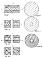
- the differential texture may vary in the plane of a layer, radially, for example to reinforce the central part of a brake disc, as illustrated in Figures 4-3 and 4-4 or to reinforce the external part, as illustrated in figures 8-1 and 8-2.
- the expression "differential texture” therefore covers different scenarios. Some cases have been represented on plates 4, 5, and 8 to illustrate the concept of differential texture.
- the coarse-textured fiber substrate (5g) is made up of wicks (tissue) or wick segments, its apparent density before densification is between 0.3 and 0.7, while that of the fine-textured fibrous substrate is between between 0.05 and 0.3.
- the overall apparent density of the fibrous substrate (5g) and (5f) is between 0.1 and 0.7.
- the carbon matrix of the multilayer CC composite is not specific to the invention and results, in known manner, from the densification of the substrate compressed fibrous, either by chemical deposition of pyrolytic carbon in the vapor phase, or by one or more impregnation treatments with a resin or a pitch leading to a high carbon level after carbonization, treatments followed by carbonization, or association of the two processes.
- the friction element according to the invention is a C-C composite material with a density between 1.55 and 1.8, which can optionally be subjected to a subsequent graphitization treatment.
- the invention also relates to friction elements constituted by an assembly of structural layers (1) in CC composite and friction layers (2) in CC composite, obtained respectively by densification of coarse-textured fibrous substrate (5 g) and of fibrous substrate with fine texture (5f), the assembly being able to be carried out by any known means, in particular by a bonding layer (4).
- a bonding layer (4) of a resin which leads by heating to the formation of a carbonaceous layer, generally porous.
- the friction element obtained by assembly can have a continuous carbon matrix on the whole of the friction element because it is advantageous to assemble layers of structure and friction having a residual porosity and to finish the manufacture of the friction element by a carbon deposit so as to densify all of the layers as well as the bonding layer (4).
- the invention makes it possible to obtain friction elements which are generally in the form of discs of diameter which can reach, or even exceed, 600 mm (outside diameter) and typically can have a central structure layer with a thickness of the order of 10 - 20 mm, covered with two friction layers with a thickness of around 3 - 7 mm.
- the invention makes it possible to obtain, thanks to the differential texture of the structure and friction layers in CC composite, high specific performances, that is to say considered per kilogram of friction element, both in which concerns the mechanical properties, the resilience in particular, that the tribological properties, the resistance to wear mainly. As is known, it is therefore possible to renovate a friction element by replacing the worn friction layer with a new layer obtained according to the invention.
- the friction element according to the invention has, in particular in the case of a fibrous substrate made up of wick or fiber segments, the advantage of not comprising a local absence of substrate on the scale dimensions of the local substrate, that is to say within a maximum volume of approximately 0.05 mm3 for a fibrous substrate with a fine texture and approximately 5 mm3 for a substrate with a coarse texture.
- the second object of the invention is a method of economical manufacture of these friction elements made of composite C-C.
- the method for manufacturing a friction element in a multilayer carbon-carbon composite consisting of a structural layer (1) and at least one friction layer (2) comprises a step of manufacturing d '' a fibrous substrate with a desired geometric shape, a possible carbonization step if said fibrous substrate is at carbon fiber precursor base, and a step of densifying said fibrous substrate by depositing carbon to form the carbon matrix, said step of manufacturing the fibrous substrate with a desired geometric shape is characterized in that all or part of said substrate is manufactured fibrous by introducing into a mold (10), possibly using a distribution device, segments of wicks made of carbon fiber or carbon precursor of length between 5 and 60 mm to constitute the fibrous substrate (5 g ) of the structural layer (1), segments of carbon fibers or carbon precursor of length between 0.05 and 60 mm to constitute the fibrous substrate (5f) of the friction layer (2), and compressing the segments of wicks and fibers, so as to obtain a fibrous substrate (5f, 5g) with an overall apparent density of between 0.1
- the compressed fibrous substrate has the general shape of the mold, which will therefore be cylindrical if the friction element must be in the form of a disc, which is generally the case.
- the method makes it possible to manufacture fibrous substrates with a cross section of any geometric shape.
- only part of the fibrous substrate is formed from wick segments and / or fibers and its preparation is completed by adding elements cut from carbon sheets or carbon precursor, sheets made of fabrics or felt / mat depending on whether a fibrous substrate with a coarse or fine texture is desired.
- These different parts of the substrate can be assembled using adhesives or by compression.
- the overall fibrous substrate is subjected to a densification treatment by carbon deposition.
- the method for manufacturing a friction element in a multilayer carbon-carbon composite consisting of a structure layer and at least one friction layer comprises the manufacture of a structure layer (1) in carbon-carbon composite and at least one friction layer (2) in carbon-carbon composite, their assembly by any known means, such as a bonding layer (4), characterized in that the structural layer is produced by carbon deposition on a coarse-textured fibrous substrate (5g) having a median pore diameter greater than 100 "m and the friction layer is produced by carbon deposition on a fine-textured fibrous substrate (5f) having a diameter of median pore less than 50 ⁇ m, the fibrous substrates being carbonized beforehand in the case of a fibrous substrate made of carbon fiber precursor.
- a coarse-textured fibrous substrate (5g) having a median pore diameter greater than 100 "m
- the friction layer is produced by carbon deposition on a fine-textured fibrous substrate (5f) having a diameter of median pore less than 50 ⁇ m
- the coarse-textured fibrous substrate (5g) is obtained from a sheet, a carbon fiber or carbon precursor fabric, or from wick segments of carbon fibers or carbon precursor, length between 5 and 60 mm, possibly placed in a mold using a dispensing device and then compressed until an apparent density of between 0.3 and 0.7 is obtained.
- the fine-textured fibrous substrate (5f) is obtained from a mat, a carbon fiber felt or carbon precursor, or from segments of carbon fibers or carbon precursor, of length included between 0.05 and 60 mm, placed in a mold (10), possibly using a dispensing device, then optionally compressed until an apparent density of between 0.05 and 0.3 is obtained.
- This second method can therefore be advantageously used for the renovation of worn friction elements no longer comprising in practice only a structural layer (1) of CC composite.
- it is also possible to renovate a worn friction element by subjecting to carbon densification a layer of structure (1) in CC composite coated with at least one layer of fibrous substrate (5f) with fine texture, this modality constituting in a way a mixture of the two previous terms.
- the fibrous substrate comprises wick or fiber segments
- the applicant has developed a device for distributing wick and / or fiber segments which is very efficient for the implementation of the process, ensuring automatic filling of the mold.
- the device for distributing wick or fiber segments comprises at least one dispensing head (8) of wick and / or fiber segments, in relative movement relative to the mold (10) and sweeping the the entire horizontal surface of the mold, so as to fill progressively and regularly, in successive layers, the mold with randomly oriented segments of wicks (9) and / or carbon fibers (6) while maintaining a distribution plane (7 ) substantially horizontal, the proportion of wick segments and / or carbon fibers distributed by the said head (s) being preferably controlled by the coordinates (z, ⁇ , ⁇ ) of the plane portion of distribution receiving the wick and / or carbon fiber segments, so as to have locally in the mold, and in a predetermined manner, a fibrous substrate of the desired texture which can range, after possible compression, from a fine texture with a diameter of pore s median less than 50 »m, with a coarse texture with median pore diameter greater than 100» m.
- This dispensing device comprises one or more dispensing heads (8), optionally attached, provided with means of continuous or step-by-step feeding in wick (s) of carbon fibers of great length, possibly sized or prepreg, means for cutting the wick (s) into segments (6,9) of predetermined length, possible means for facilitating the dispersion of the segments obtained from wicks which may be sized or prepreg so as to obtain fiber segments (6) , means either of displacement of the head (s) itself (s) or of transport of the segments obtained from continuous wicks so that the filling of the mold is done in successive layers substantially horizontal (7) and that the segments (6,9) are placed at a precise point in the mold defined by its coordinates (z, ⁇ , ⁇ ), finally by computer means for controlling the proportion of segments of fibers / wicks (defined by the volume percentage of one of the two kinds of segments) at the position of the segments in the mold so as to have locally in the friction element the desired texture according to a predetermined filling program.
- the device can have two dispensing heads, one, supplied with a wick of sized or prepreg carbon fibers, providing segments of wicks (9), the other, supplied with a wick of carbon fibers, neither sized nor prepreg, providing segments of fibers (6).
- This latter head can, according to a variant, be supplied with crushed fibers of carbon or of carbon precursor, providing segments of fibers (6).
- the device can have a single dispensing head, supplied with a wick of sized carbon fibers or prepreg, supplying at a given location in the mold and depending on the filling program, wick segments (9) of length. at least equal to 5 mm and / or segments of fibers (6) of length less than 5 mm.
- the head is provided with a means for cutting the wicks to a predetermined length and provided with a means for dispersing the wick segments, which can be activated when fiber segments (6) are to be deposited in the mold.
- wick segments (9) it is important that the wicks of carbon fibers (or of precursor) remain in the form of a wick and do not tend to disperse into isolated fibers.
- wicks of carbon fibers (or precursor), preferably sized or preimpregnated with resin, are cut.
- the fiber segments (6) consist of isolated fibers, or, failing this, of a small number of associated fibers.
- segments of fibers (6) can also be obtained from segments of sized or preimpregnated wicks of short length, by means of dispersing means sufficient to disperse these segments of wicks into segments of fibers. It may be advantageous to feed the head intended to deliver segments of fibers (6) not in long strands but directly in segments of fibers.
- segments of short fibers of average length can be obtained by grinding off scraps or various residues of fibers, which constitutes a particularly economical source of supply.
- the ground carbon fiber is in the form of a powder which can be transported and moved either by gravity, or by pneumatic drive, or finally in the form of a dispersion in a liquid.
- the gas or the liquid supporting the powder is evacuated, preferably by the bottom of the mold, the bottom of the mold will be pierced with holes and possibly provided with means allowing the suction of the gas or the liquid to be through the bottom of the mold.
- the device according to the invention makes it possible to produce, in a reproducible and automatic manner, any profile of fibrous substrate with variable texture by "linear combination" of two materials, one with a fine texture, the other with a coarse texture.
- the invention makes it possible to obtain a three-dimensional fibrous substrate with segments of wicks and / or entangled fibers whose texture is predetermined as a function of the coordinates (z, ⁇ , ⁇ ) of any point or portion of volume in the space occupied by the fibrous substrate constituting the reinforcement of the friction element. This process therefore lends itself to full automation, which also makes it possible to change manufacturing, possibly by simply modifying the mold filling program. Plates 4, 5, and 8 illustrate some of these possibilities, in particular the simple case where the fibrous substrate consists of layers with a homogeneous texture per plane (fig. 4-1, 4-2, 5-2).
- the invention therefore constitutes a means of reproducibly and automatically manufacturing friction elements having a fibrous substrate of any texture. predetermined, so that it is possible to obtain both "tailor-made” friction elements, at competitive prices and meeting the requirements of quality assurance. Indeed, these friction elements must, in many cases, satisfy a high level of quality assurance, hardly compatible with manufacturing processes that are poorly or not automated, knowing that in the manufacture of a composite material, the matrix continues poses fewer quality problems than the dicontinuous substrate.
- Competitive prices result from several elements: saving material since a friction element can be directly obtained in the desired shape, possibility of using carbon wicks less expensive than fabrics or crushed carbon fibers, in turn less costly than carbon wicks, finally economy of the process linked to its automation.
- Figure 1-1 shows schematically in cross section a multilayer friction element comprising a structure layer (1) and, on either side thereof, two friction layers (2).
- Figure 1-2 is similar to Figure 1-1 but also has two connecting layers (4) to make the structural layer (1) and the two friction layers (2) integral.
- Figure 1-3 shows schematically the coarse texture 5g and Figure 1-4 shows the fine texture 5f, representations used in Figures 1-1, 1-2, 4-1 to 4-4.
- Figure 2-1 shows schematically a coarse texture 5g made up of wick segments (9).
- Figure 2-2 schematically shows a fine texture 5f consisting of segments of carbon fibers (unitary fibers or small number of associated unit fibers) (6).
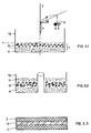
- Figure 3-1 shows in vertical section, a mold (10) being filled using two associated dispensing heads (8), one of fiber segments and one of wick segments.
- Computer means (not shown in the figure), with a mold filling program, ensure the movement of the heads, whose position is defined by its coordinates (z, ⁇ , ⁇ ), and the distribution of wicks locally producing the texture desired, provided by the program (fine / coarse / or intermediate by mixing the two textures), so as to fill the mold with successive layers (11, 12).
- Figure 3-2 is similar to Figure 3-1, but the mold has a central hole.
- Figure 3-3 shows schematically the case where the structure layer (1) is constituted by a stack of oriented fibrous substrate (13) which is introduced into the mold during filling.
- Figures 4-1 to 4-4 show sections along the Z axis of different friction elements of variable geometry and texture.
- Figures 4-1A to 4-3A show the texture of the fibrous substrate in the plane AA 'perpendicular to the axis Z.
- Figures 5-1 to 5-3 include for each of them the diagram of the texture of the fibrous substrate in section as well as a diagram on the abscissa the texture which goes from “f” to "g", "f” representing the fine texture and "g” the coarse texture, and on the ordinate Z the distance z of a layer from the lower part of the fibrous substrate taken as the origin.
- Figure 5-1 shows a discontinuity in the fibrous substrate.
- Figures 5-2 and 5-3 show a continuity of the fibrous substrate, with for Figure 5-2 a zone of mixing the segments of wicks and fibers, of thin thickness, whereas in Figure 5-3, the passage of the segment layer of only strands (12) of the layers of fiber segments alone (11) are made progressively over a relatively large thickness.
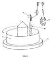
- FIG. 6 represents a simplified device which was used to carry out examples 1 to 3.
- a mold (10) with central orifice is installed on a rotating drum (14).
- a distribution head (8) cuts and distributes segments (9, 6) either of wicks or of fibers depending on the nature of the reel (15) of carbon fiber (respectively sized or not).
- Figure 7-1 shows the distribution of porosity by pore class for the coarse-textured compressed fibrous substrate of Example 1.
- Figure 7-2 shows the same distribution but for the fine-textured compressed substrate.
- On the abscissa is the pore diameter in »m, with the intervals for each class of pores (non-linear scale).
- On the ordinate the percentage of pore volume per pore class, relative to the total volume of the sample, is shown.
- Figures 8-1 and 8-2 show in section along the Z axis other examples of friction elements, with peripheral reinforcement of the structural layer, unlike Figures 4-3 and 4-4 which have a reinforcement axial.
- a first layer with a fine texture, was formed on a thickness of 60 mm, consisting of segments of fibers. These fiber segments were obtained from a strand of long carbon fiber, 12,000 elementary fibers, by cutting it into segments of 1 mm in length. This wick is neither sized nor pre-impregnated, the wick segments are dispersible into segments of elementary fibers oriented randomly in the mold.
- a second, coarse-textured layer was formed over a thickness of 80 mm, made up of wick segments. These segments were obtained from a sizing wick of very long carbon fibers, with 12,000 elementary fibers by cutting it into 20 mm segments. It was observed that the wick segments did not tend to dissociate.
- the fibrous substrate thus obtained was compressed in the mold. Its height after compression is 26 mm. It consists of 3 layers. Each type of layer was characterized, that of coarse texture and that of fine texture after beginning of densification by carbon deposition to an apparent density of approximately 0.9:
- the coarse-textured layer has a porosity (pore volume) of 30%.
- the distribution of the diameter of its pores is that of Figure 7-1. By simple interpolation calculation, it is established that the median pore diameter is close to 140 "m.
- the fine texture layer has a porosity of 42%.
- the distribution of the diameter of its pores is that of Figure 7-2. Its average pore diameter is close to 13 ”m.
- the compressed fibrous substrate which can be handled and which has substantially the final dimensions of the friction element to be obtained, has been subjected to a densification step by vapor phase deposition of pyrolytic carbon at a temperature of 1050 ° C.
- a friction element made of composite material is thus obtained. density 1.75.
- a friction element was produced which differs by the structural layer (1): a wick of 6000 elementary fibers was used instead of 12000 in example 1. The other parameters remained identical.
- a fibrous substrate of the structure layer (1) with a coarse texture was used a stack of fabrics obtained from locks of 3000 elementary fibers. The other parameters have remained the same.
- Example 1 As the fibrous substrate, fine-textured friction layers of Example 1 were used, ground carbon fiber powder consisting of segments of fibers of average length of the order of 200 ⁇ m. A mold with a perforated bottom was used so as to be able to introduce the carbon fiber powder in the form of a dispersion in an aqueous medium, which limits the nuisance due to dust. After compression, a fibrous substrate 27 mm thick was obtained, consisting of a coarse-textured central layer 17 mm thick and with an apparent density of 0.5, and consisting of two fine-textured side layers of each. 5 mm thick and 0.15 bulk density. Its overall apparent density is 0.175. The other elements of the test are those of Example 1.
Landscapes
- Chemical & Material Sciences (AREA)
- Engineering & Computer Science (AREA)
- Ceramic Engineering (AREA)
- Materials Engineering (AREA)
- Structural Engineering (AREA)
- Organic Chemistry (AREA)
- General Engineering & Computer Science (AREA)
- Composite Materials (AREA)
- Chemical Kinetics & Catalysis (AREA)
- Manufacturing & Machinery (AREA)
- Mechanical Engineering (AREA)
- Dispersion Chemistry (AREA)
- Braking Arrangements (AREA)
- Ceramic Products (AREA)
- Laminated Bodies (AREA)
- Carbon And Carbon Compounds (AREA)
- Manufacture Of Macromolecular Shaped Articles (AREA)
Claims (22)
- Mehrschichtreibelement mit einer Strukturschicht (1) aus Kohlenstoff-Kohlenstoff-Verbundwerkstoff, von der wenigstens eine Seite mit einer Reibschicht (2) aus Kohlenstoff-Kohlenstoff-Verbundwerkstoff bedeckt ist, die mit der Strukturschicht (1) fest verbunden ist, dadurch gekennzeichnet,
daß einerseits die Strukturschicht (1) aus einem Fasersubstrat (5g) mit als "grob" bezeichneter Textur erhalten ist, das 10 bis 50 Vol.-% der Schicht (1) darstellt, einen mittleren Porendurchmesser von über 100 »m hat und aus Bündeln aus Kohlenstoffaser oder Kohlenstoffaservorläufer besteht, und daß andererseits die Reibschicht (2) aus einem Fasersubstrat (5f) mit als "fein" bezeichneter Textur erhalten ist, das 3 bis 25 Vol.-% der Schicht (2) darstellt, einen mittleren Porendurchmesser von unter 50 »m aufweist und aus zufällig verteilten Stücken (6) aus Kohlenstoffaser oder Kohlenstoffaservorläufer besteht. - Reibelement nach Anspruch 1, bei dem die Strukturschicht (1) aus einem Fasersubstrat (5g) erhalten ist, das aus zufällig verteilten Stücken von Bündeln (9) aus Kohlenstoffaser oder Kohlenstoffaservorläufer besteht.
- Reibelement nach Anspruch 2, bei dem die Länge des Bündelstücks zwischen 5 und 60 mm und die des Faserstücks zwischen 0,05 und 60 mm liegt.
- Reibelement nach Anspruch 3, bei dem die Länge des Faserstücks zwischen 1 und 60 mm liegt.
- Reibelement nach einem der Ansprüche 1 bis 4, bei dem das Fasersubstrat ein ununterbrochenes Gewirr von Bündelstücken (9) in der Strukturschicht (1) bzw. Faserstücken (6) in der Reibschicht (2) bzw. Bündel- und Faserstücken in beliebigen Verhältnissen im Zwischenbereich zwischen der Strukturschicht und der Reibschicht bildet.
- Reibelement nach Anspruch 1, bei dem das Fasersubstrat (5g) der Strukturschicht (1) ein orientiertes Fasersubstrat (13), typischerweise auf Grundlage von Geweben aus Kohlenstoffaser oder Kohlenstoffaservorläufer, umfaßt.
- Reibelement nach einem der Ansprüche 1 bis 4 und 6, bei dem das Fasersubstrat (5f) der Reibschicht (2) aus einem Filz oder Vlies aus Kohlenstoffasern oder Kohlenstoffaservorläufer besteht.
- Reibelement nach einem der Ansprüche 1 bis 7, bei dem die Strukturschicht aus einem komprimierten Fasersubstrat (5g) mit einer scheinbaren Dichte zwischen 0,3 und 0,7 erhalten ist.
- Reibelement nach einem der Ansprüche 1 bis 8, bei dem die Reibschicht aus einem Fasersubstrat (5f) mit einer scheinbaren Dichte zwischen 0,05 und 0,3 erhalten ist.
- Reibelement nach einem der Ansprüche 1 bis 4, 6 bis 9, bei dem die Strukturschicht (1) und die Reibschicht (2) durch eine Verbindungsschicht (4) fest verbunden sind.
- Reibelement nach einem der Ansprüche 1 bis 10, bei dem das Fasersubstrat (5f) der Reibschicht (2) gemahlene Kohlenstoffaser umfaßt, die aus Faserstücken mit einer mittleren Länge zwischen 0,05 und 1 mm besteht.
- Reibelement nach einem der Ansprüche 1 bis 11, bei dem die Bündel mehr als 1000 Einzelfasern umfassen und die Faserstücke weniger als 100 Einzelfasern umfassen.
- Verfahren zur Herstellung eines Reibelements aus Mehrschicht-Kohlenstoff-Kohlenstoff-Verbundwerkstoff mit einer Strukturschicht (1) und wenigstens einer Reibschicht (2) nach Anspruch 1, das einen Schritt der Herstellung eines Fasersubstrats in einer gewünschten geometrischen Form, eventuell einen Schritt der Verkohlung, wenn das Fasersubstrat ein Substrat auf Grundlage von Kohlenstoffaservorläufer ist, und einen Schritt der Verdichtung des Fasersubstrats durch Abscheiden von Kohlenstoff zum Bilden der kohlenstoffhaltigen Matrix umfaßt, wobei der Schritt der Herstellung des Fasersubstrats in der gewünschten geometrischen Form dadurch gekennzeichnet ist, daß das gesamte Fasersubstrat oder ein Teil davon hergestellt wird, indem in eine Form (10) eventuell mit Hilfe einer Verteilervorrichtung, Stücke von Bündeln aus Kohlenstoffaser oder Kohlenstoffaservorläufer mit einer Länge zwischen 5 und 60 mm eingeführt werden, um das Fasersubstrat (5g) der Strukturschicht (1) zu bilden, und Stücke aus Kohlenstoffaser oder Kohlenstoffaservorläufer mit einer Länge zwischen 0,05 und 60 mm eingeführt werden, um das Fasersubstrat (5f) der Reibschicht (2) zu bilden, dann die Elemente (1) und (2) durch eine Verbindungsschicht (4) zusammengefügt werden und/oder die Bündel- und Faserstücke komprimiert werden, bis eine scheinbare Gesamtdichte zwischen 0,1 und 0,7 erreicht ist.
- Verfahren nach Anspruch 13, bei dem das Fasersubstrat (5g) mit grober Textur aus einer Lage oder einem Gewebe aus Kohlenstoffaser oder Kohlenstoffaservorläufer oder aus Stücken von Bündeln aus Kohlenstoffaser oder Kohlenstoffaservorläufer mit einer Länge von zwischen 5 und 60 mm erhalten wird, die in eine Form eventuell mit Hilfe einer Verteilervorrichtung eingeführt und dann komprimiert werden, bis eine scheinbare Dichte von zwischen 0,3 und 0,7 erreicht ist.
- Herstellungsverfahren nach Anspruch 13, bei dem das Fasersubstrat (5f) mit feiner Textur aus einem Vlies oder Filz aus Kohlenstoffaser oder Kohlenstoffaservorläufer oder aus Stücken aus Kohlenstoffaser oder Kohlenstoffaservorläufer mit einer Länge von zwischen 0,05 und 60 mm erhalten wird, die in eine Form (10) eventuell mit Hilfe einer Verteilervorrichtung eingeführt und eventuell komprimiert werden, bis eine scheinbare Gesamtdichte von zwischen 0,1 und 0,7 erreicht ist.
- Verfahren nach Anspruch 15, bei dem das Fasersubstrat (5f) aus Stücken aus Kohlenstoffaser oder Kohlenstoffaservorläufer mit einer Länge von zwischen 1 und 60 mm erhalten wird.
- Verfahren nach einem der Ansprüche 13 bis 16, dadurch gekennzeichnet,
daß die Verbindungsschicht (4) durch Komprimieren der Bündel- und Faserstücke erhalten wird, um so ein Fasersubstrat (5f, 5g) mit scheinbarer Gesamtdichte von zwischen 0,1 und 0,7 zu erhalten, das aus verworrenen, zufällig orientierten Stücken von Bündeln und/oder Fasern besteht. - Herstellungsverfahren nach einem der Ansprüche 13 bis 17, bei dem die Verteilervorrichtung zum Verteilen der Bündel- oder Faserstücke wenigstens einen Verteilerkopf (8) zum Verteilen der Bündel- oder Faserstücke umfaßt, der sich relativ zur Form (10) bewegt und die gesamte horizontale Oberfläche der Form überstreicht, um fortschreitend und gleichmäßig in aufeinanderfolgenden Schichten die Form mit zufällig orientierten Stücken von Bündeln (9) und/oder Fasern (6) aus Kohlenstoff zu füllen und dabei eine im wesentlichen horizontale Verteilungsebene (7) aufrechtzuerhalten, wobei das relative Verhältnis der von dem oder den Köpfen verteilten Bündel- und/oder Faserstücke vorzugsweise in Abhängigkeit von den Koordinaten (z, ρ, ϑ) des Abschnitts der Verteilungsebene gesteuert wird, der die Bündel- und/oder Faserstücke aufnimmt, um so lokal in der Form in vorgegebener Weise ein Fasersubstrat mit der gewünschten Textur zu erhalten, die nach Kompression von einer feinen Textur mit mittlerem Porendurchmesser unter 50 »m bis zu einer groben Textur mit mittlerem Porendurchmesser von über 100 »m reichen kann.
- Vorrichtung zum Verteilen von Stücken von Kohlenstoffasern oder -faserbündeln in einer Form, mit einem oder mehreren Verteilerköpfen (8), die aneinanderhängen können, Mitteln zur kontinuierlichen oder schrittweisen Versorgung mit einem oder mehreren Bündeln aus Kohlenstoffasern großer Länge, die geölt oder vorimprägniert sein können, Mitteln zum Schneiden des oder der Bündel in Stücke (6, 9) von vorgegebener Länge, eventuell Mitteln zum Erleichtern des Zerlegens der aus den eventuell geölten oder vorimprägnierten Bündeln erhaltenen Stücke, um Faserstücke (6) zu erhalten, Mitteln zum Bewegen des oder der Köpfe selber oder zum Transport der aus den kontinuierlichen Bündeln erhaltenen Stücke, so daß die Befüllung der Form in aufeinanderfolgenden, im wesentlichen horizontalen Schichten (7) abläuft und die Stücke (6, 9) an einem genauen, durch seine Koordinaten (z, ρ, ϑ) definierten Punkt der Form angeordnet werden, sowie Datenverarbeitungsmitteln zum Steuern des Verhältnisses von Bündel- zu Faserstücken (definiert durch den Volumenprozentsatz einer der zwei Arten von Stücken) am Ort der Segmente in der Form, um so lokal in dem Reibelement nach einem der Ansprüche 1 bis 12 nach einem vorgegebenen Füllprogramm die gewünschte Textur zu erhalten.
- Vorrichtung nach Anspruch 19, bei der zwei Verteilerköpfe verwendet werden, von denen einer, der mit geöltem oder vorimprägniertem Kohlenstoffaserbündel versorgt wird, Bündelstücke (9) liefert und der andere, der mit einem weder geölten noch vorimprägnierten Kohlenstoffaserbündel versorgt wird, Faserstücke (6) liefert.
- Vorrichtung nach Anspruch 19, bei der zwei Verteilerköpfe verwendet werden, von denen einer, der mit geölter oder vorimprägnierter Kohlenstoffaser versorgt wird, Bündelstücke (9) liefert und der andere, der mit gemahlenen Kohlenstoffasern oder Kohlenstoffvorläuferfaser versorgt wird, Faserstücke (6) liefert.
- Vorrichtung nach Anspruch 19, bei der ein Verteilerkopf verwendet wird, der mit geölter oder vorimprägnierter Kohlenstoffaser versorgt wird und an einer gegebenen Stelle der Form und in Abhängigkeit vom Füllprogramm Bündelstücke (9) mit einer Länge von wenigstens 5 mm und/oder Faserstücke (6) mit einer Länge von unter 5 mm liefert.
Applications Claiming Priority (4)
| Application Number | Priority Date | Filing Date | Title |
|---|---|---|---|
| FR9006488A FR2661866B1 (fr) | 1990-05-10 | 1990-05-10 | Element de friction multicouches en materiau composite carbone-carbone a texture differentielle et son procede de fabrication. |
| FR9006488 | 1990-05-10 | ||
| FR9103827A FR2674587A1 (fr) | 1991-03-25 | 1991-03-25 | Elements de friction en materiau composite carbone-carbone a texture differentielle, procedes et dispositifs pour les fabriquer. |
| FR9103827 | 1991-03-25 |
Publications (2)
| Publication Number | Publication Date |
|---|---|
| EP0459916A1 EP0459916A1 (de) | 1991-12-04 |
| EP0459916B1 true EP0459916B1 (de) | 1995-04-12 |
Family
ID=26228034
Family Applications (1)
| Application Number | Title | Priority Date | Filing Date |
|---|---|---|---|
| EP19910420150 Expired - Lifetime EP0459916B1 (de) | 1990-05-10 | 1991-05-06 | Reibelemente aus Kohlenstoff-Kohlenstoff-Verbundwerkstoff mit verschiedener Textur, Verfahren und Vorrichtungen zu ihrer Herstellung |
Country Status (7)
| Country | Link |
|---|---|
| US (1) | US5242746A (de) |
| EP (1) | EP0459916B1 (de) |
| JP (1) | JPH06241253A (de) |
| AT (1) | ATE121060T1 (de) |
| BR (1) | BR9101857A (de) |
| CA (1) | CA2041921A1 (de) |
| DE (1) | DE69108776T2 (de) |
Families Citing this family (70)
| Publication number | Priority date | Publication date | Assignee | Title |
|---|---|---|---|---|
| DE4119515C1 (de) * | 1991-06-13 | 1992-12-10 | Textar Gmbh, 5090 Leverkusen, De | |
| DE69319284T2 (de) * | 1992-07-23 | 1998-12-17 | Le Carbone Lorraine, Courbevoie, Hauts-De-Seine | Kohlenstoff/Kohlenstoff Verbundstoffreibungsmaterial mit aufgeteilter Porosität |
| US6405417B1 (en) | 1994-07-25 | 2002-06-18 | Goodrich Corporation | Process for forming fibrous structures with predetermined Z-fiber distributions |
| US6029327A (en) | 1994-07-25 | 2000-02-29 | The B.F. Goodrich Company | Process for forming fibrous structures with predetermined Z-fiber distributions |
| ATE215518T1 (de) * | 1994-11-16 | 2002-04-15 | Goodrich Co B F | Vorrichtung zur druckfeld cvd/cvi, verfahren und produkt |
| US5803210A (en) * | 1994-12-28 | 1998-09-08 | Nippon Oil Co., Ltd. | Disk brakes |
| GB9504904D0 (en) * | 1995-03-10 | 1995-04-26 | Dunlop Ltd | Composite brake disc |
| US5680921A (en) * | 1996-02-07 | 1997-10-28 | Borg-Warner Automotive, Inc. | Transmission band assembly |
| CA2202432C (en) | 1996-05-17 | 2006-09-12 | Marc A. Yesnik | Two-ply friction material |
| FR2754031B1 (fr) | 1996-09-30 | 1998-12-18 | Carbone Ind | Elaboration de preformes fibreuses pour la fabrication de disques de frein en materiau composite |
| RU2114338C1 (ru) * | 1996-11-20 | 1998-06-27 | Открытое акционерное общество Научно-исследовательский и конструкторско-технологический институт асбестовых технических изделий - фирма "ТИИР" | Фрикционное изделие |
| US5775468A (en) * | 1997-01-16 | 1998-07-07 | Borg-Warner Automotive, Inc. | High performance two-ply friction material |
| JP4163270B2 (ja) * | 1997-03-26 | 2008-10-08 | 本田技研工業株式会社 | 湿式摩擦クラッチ用c/cコンポジット製クラッチディスクおよびその製造方法 |
| US5878843A (en) * | 1997-09-24 | 1999-03-09 | Hayes Lemmerz International, Inc. | Laminated brake rotor |
| DE19834704C2 (de) * | 1998-07-31 | 2002-08-01 | Knorr Bremse Systeme | Reibring bzw. Reibelement für eine Reibbremse, insbesondere Scheibenbremse |
| KR20000046412A (ko) * | 1998-12-31 | 2000-07-25 | 추호석 | 탄소/탄소 복합재료 브레이크 디스크 제조방법 |
| DE19901215B4 (de) * | 1999-01-14 | 2004-02-19 | Menzolit-Fibron Gmbh | Scheibenbremse, Preßwerkzeug und Verfahren zur Herstellung einer Bremsscheibe |
| US6213260B1 (en) * | 1999-10-05 | 2001-04-10 | Brake Tru, Inc. | Brake pad and methods of braking and resurfacing a rotatable brake member |
| ATE333054T1 (de) † | 2000-02-09 | 2006-08-15 | Freni Brembo Spa | Bremsscheibe für eine scheibenbremse |
| DE10014418C5 (de) * | 2000-03-24 | 2006-05-04 | Daimlerchrysler Ag | Verfahren zur Herstellung eines faserverstärkten Strukturbauteils und danach hergestellte Bremsscheibe |
| IT1315422B1 (it) * | 2000-04-13 | 2003-02-10 | Vittorio Pareti | Componenti frenanti particolarmente per freni di veicoli. |
| DE10048012A1 (de) | 2000-09-26 | 2002-04-11 | Sgl Carbon Ag | Reib- oder Gleitkörper aus mit Faserbündeln verstärkten Verbundwerkstoffen mit keramischer Matrix |
| DE10060566B4 (de) * | 2000-12-01 | 2005-09-08 | Dr.Ing.H.C. F. Porsche Ag | Reibkörper aus siliziuminfiltriertem, kohlenstofffaserverstärktem porösen Kohlenstoff, Verfahren zum Herstellen eines solchen Reibkörpers und Verwendung eines solchen Reibkörpers |
| DE10148658C1 (de) * | 2001-10-02 | 2003-02-06 | Sgl Carbon Ag | Verfahren zur Herstellung von Hohlkörpern aus faserverstärkten keramischen Materialien |
| JP4425548B2 (ja) | 2003-01-24 | 2010-03-03 | イーグル工業株式会社 | シール用摺動部材及びその製造方法 |
| US7641941B2 (en) * | 2003-04-22 | 2010-01-05 | Goodrich Corporation | Oxidation inhibition of carbon-carbon composites |
| GB2403989B (en) * | 2003-07-15 | 2006-06-14 | Dunlop Aerospace Ltd | Composite article |
| FR2858672B1 (fr) * | 2003-08-07 | 2006-10-13 | Valeo Materiaux Friction | Garniture de frottement et procede de fabrication d'une telle garniture de frottement |
| KR100588342B1 (ko) * | 2003-11-26 | 2006-06-12 | 주식회사 데크 | 동력전달용 클러치 |
| US20100000070A1 (en) * | 2004-04-01 | 2010-01-07 | La Forest Mark L | Reusable core carbon-carbon composite brake disc |
| JP4673571B2 (ja) * | 2004-04-02 | 2011-04-20 | 本田技研工業株式会社 | 摩擦係合装置用摩擦部材およびその製造方法 |
| DE102005052802A1 (de) * | 2005-11-05 | 2007-05-10 | Audi Ag | Bremsscheibe mit Zwischenschicht |
| US20070154712A1 (en) * | 2005-12-22 | 2007-07-05 | Mazany Anthony M | Oxidation inhibition of carbon-carbon composites |
| US8182905B2 (en) * | 2006-01-20 | 2012-05-22 | United Technologies Corporation | Ceramic matrix laminates |
| EP1845075B1 (de) | 2006-04-11 | 2016-04-06 | SGL Carbon SE | Formkörper aus carbonfaserverstärktem Kohlenstoff und ein Verfahren zur deren Herstellung |
| ATE486828T1 (de) * | 2006-04-11 | 2010-11-15 | Sgl Carbon Se | Verfahren zum imprägnieren von kurzfaserbündeln aus carbonfasern |
| EP2065109B1 (de) * | 2006-08-22 | 2018-12-05 | Kureha Corporation | Kohlenstofffasern enthaltender laminierter formkörper und herstellungsverfahren dafür |
| CN101429297B (zh) * | 2008-12-17 | 2011-09-07 | 黄山奔马集团有限公司 | 一种摩擦片材料及其使用方法 |
| KR101304188B1 (ko) * | 2010-11-29 | 2013-09-05 | 주식회사 데크 | 탄소-세라믹 브레이크 디스크 및 이를 만드는 방법 |
| KR101304309B1 (ko) * | 2010-11-29 | 2013-09-11 | 주식회사 데크 | 탄소-세라믹 브레이크 디스크 |
| US8597772B2 (en) * | 2011-09-20 | 2013-12-03 | Honeywell International Inc. | Corrugated carbon fiber preform |
| DE112014002669A5 (de) * | 2013-06-04 | 2016-02-18 | Schaeffler Technologies AG & Co. KG | Mehrschichtiger Reibbelag |
| US20160279710A1 (en) * | 2015-03-25 | 2016-09-29 | Goodrich Corporation | Aircraft brake rotor clip repair methods |
| US10087101B2 (en) | 2015-03-27 | 2018-10-02 | Goodrich Corporation | Formulations for oxidation protection of composite articles |
| US10302163B2 (en) | 2015-05-13 | 2019-05-28 | Honeywell International Inc. | Carbon-carbon composite component with antioxidant coating |
| US10131113B2 (en) | 2015-05-13 | 2018-11-20 | Honeywell International Inc. | Multilayered carbon-carbon composite |
| US9944526B2 (en) | 2015-05-13 | 2018-04-17 | Honeywell International Inc. | Carbon fiber preforms |
| US10035305B2 (en) | 2015-06-30 | 2018-07-31 | Honeywell International Inc. | Method of making carbon fiber preforms |
| US10022890B2 (en) | 2015-09-15 | 2018-07-17 | Honeywell International Inc. | In situ carbonization of a resin to form a carbon-carbon composite |
| US10300631B2 (en) | 2015-11-30 | 2019-05-28 | Honeywell International Inc. | Carbon fiber preforms |
| EP3435894B1 (de) | 2016-03-30 | 2025-01-22 | Alcon Inc. | Zusammengesetzte betätigungsgriffe für ein chirurgisches instrument |
| US10377675B2 (en) | 2016-05-31 | 2019-08-13 | Goodrich Corporation | High temperature oxidation protection for composites |
| US10465285B2 (en) | 2016-05-31 | 2019-11-05 | Goodrich Corporation | High temperature oxidation protection for composites |
| US9982730B2 (en) * | 2016-06-21 | 2018-05-29 | Nissan North America, Inc. | Brake pad |
| US9982729B2 (en) * | 2016-06-21 | 2018-05-29 | Nissan North America, Inc. | Brake pad |
| US10508206B2 (en) | 2016-06-27 | 2019-12-17 | Goodrich Corporation | High temperature oxidation protection for composites |
| US10767059B2 (en) | 2016-08-11 | 2020-09-08 | Goodrich Corporation | High temperature oxidation protection for composites |
| US10526253B2 (en) | 2016-12-15 | 2020-01-07 | Goodrich Corporation | High temperature oxidation protection for composites |
| EP3597956A1 (de) * | 2018-07-18 | 2020-01-22 | LinkWin Technology Co., Ltd. | Bremsbelag und verfahren zur herstellung davon |
| US11046619B2 (en) | 2018-08-13 | 2021-06-29 | Goodrich Corporation | High temperature oxidation protection for composites |
| US11634213B2 (en) | 2018-11-14 | 2023-04-25 | Goodrich Corporation | High temperature oxidation protection for composites |
| US12246994B2 (en) | 2019-12-27 | 2025-03-11 | Goodrich Corporation | High temperature oxidation protection for composites |
| US12330996B2 (en) | 2021-05-05 | 2025-06-17 | Goodrich Corporation | High temperature oxidation protection for carbon-carbon composites |
| US12146538B2 (en) | 2021-09-23 | 2024-11-19 | Goodrich Corporation | Systems and methods for manufacturing wear pads |
| US12065380B2 (en) | 2021-11-16 | 2024-08-20 | Goodrich Corporation | High temperature oxidation protection for carbon-carbon composites |
| US12344564B2 (en) | 2022-01-07 | 2025-07-01 | Goodrich Corporation | Oxidation protection with improved water resistance for composites |
| US12319622B2 (en) | 2022-05-18 | 2025-06-03 | Goodrich Corporation | Oxidation protection of composites |
| US12565450B2 (en) | 2022-06-17 | 2026-03-03 | Goodrich Corporation | Oxidation protection for carbon-carbon composites |
| US12583785B2 (en) | 2023-03-20 | 2026-03-24 | Goodrich Corporation | Advanced oxidation protection system with broad temperature range capability |
| US12559634B2 (en) | 2023-03-20 | 2026-02-24 | Goodrich Corporation | Oxidation protective systems and methods of manufacture |
Family Cites Families (8)
| Publication number | Priority date | Publication date | Assignee | Title |
|---|---|---|---|---|
| US3956548A (en) * | 1973-12-20 | 1976-05-11 | Goodyear Aerospace Corporation | Duo material carbon composite brake disk |
| NO143977C (no) * | 1975-04-14 | 1981-05-20 | Goodyear Aerospace Corp | Bremseskive med lagstruktur. |
| GB2027418B (en) * | 1978-08-08 | 1982-06-16 | Kulakov V | V and others carbon friction memeber |
| FR2508999B1 (fr) * | 1981-07-01 | 1986-08-22 | Lorraine Carbone | Disque de frein en materiau composite carbone-carbone et modes de realisation |
| FR2553485B1 (fr) * | 1983-10-17 | 1989-05-05 | Goodrich Co B F | Disque de frein ou d'embrayage poreux reutilisable en composite carbone et procede de fabrication |
| DE3762544D1 (de) * | 1986-02-05 | 1990-06-07 | Europ Propulsion | Reibungssystem aus zusammengesetzten feuerfesten materialien. |
| JPS63149437A (ja) * | 1986-12-12 | 1988-06-22 | Toyota Motor Corp | 摩擦材料 |
| JPH0323265A (ja) * | 1989-06-16 | 1991-01-31 | Akebono Brake Res & Dev Center Ltd | 摩擦材用ハイブリッドc/cコンポジットとその製法 |
-
1991
- 1991-05-06 EP EP19910420150 patent/EP0459916B1/de not_active Expired - Lifetime
- 1991-05-06 AT AT91420150T patent/ATE121060T1/de not_active IP Right Cessation
- 1991-05-06 DE DE69108776T patent/DE69108776T2/de not_active Expired - Fee Related
- 1991-05-06 US US07/696,125 patent/US5242746A/en not_active Expired - Fee Related
- 1991-05-07 CA CA002041921A patent/CA2041921A1/fr not_active Abandoned
- 1991-05-08 BR BR9101857A patent/BR9101857A/pt not_active Application Discontinuation
- 1991-05-09 JP JP3133591A patent/JPH06241253A/ja active Pending
Also Published As
| Publication number | Publication date |
|---|---|
| BR9101857A (pt) | 1991-12-17 |
| JPH06241253A (ja) | 1994-08-30 |
| CA2041921A1 (fr) | 1991-11-11 |
| ATE121060T1 (de) | 1995-04-15 |
| US5242746A (en) | 1993-09-07 |
| DE69108776T2 (de) | 1995-08-24 |
| EP0459916A1 (de) | 1991-12-04 |
| DE69108776D1 (de) | 1995-05-18 |
Similar Documents
| Publication | Publication Date | Title |
|---|---|---|
| EP0459916A1 (de) | Reibelemente aus Kohlenstoff-Kohlenstoff-Verbundwerkstoff mit verschiedener Textur, Verfahren und Vorrichtungen zu ihrer Herstellung | |
| EP0886627B1 (de) | Verfahren zur herstellung von teilen, insbesondere von bremsscheiben, aus kohlenstoff-kohlenstoff-verbundwerkstoff | |
| EP3551593B1 (de) | Formausrüstung und anlage zur chemischen infiltration in der gasphase von faservorformen | |
| EP0581696B1 (de) | Kohlenstoff/Kohlenstoff Verbundstoffreibungsmaterial mit aufgeteilter Porosität | |
| EP2067757B1 (de) | Herstellungsverfahren von Verbundwerkstoffteilen mit Karbonfaserverstärkung | |
| CA2858926C (fr) | Structure fibreuse avec fils a titre variable | |
| FR2833204A1 (fr) | Realisation de preforme fibreuse aiguilletee pour fabrication de piece en materiau composite | |
| FR2886640A1 (fr) | Procede et preforme pour la realisation de pieces en materiau composite par densification cvi et pieces obtenues | |
| CA2925836C (fr) | Structure fibreuse avec regroupement des flottes | |
| FR2972448A1 (fr) | Procede de fabrication d'un composite a matrice ceramique | |
| EP3302943B1 (de) | Verfahren zum imprägnieren einer hohlen fasrigen textur | |
| EP1187950A2 (de) | Verfahren zur herstellung einer schale aus thermostrukturellem verbundmaterial, schale und deren verwendung als stütztiegel | |
| EP1219730A1 (de) | Verfahren zum Schutz eines aus Kohlenstoff, insbesondere C/C Verbundwerkstoff, Behälters zur Stützung eines Tiegels, z.B. eines Tiegels aus Quarzglas zur Züchtung von Silizium-Einkristallen | |
| EP2227384B1 (de) | Verfahren zur herstellung einer zellenförmigen faserstruktur | |
| EP1153000B1 (de) | Verfahren zur herstellung einer schale aus thermobeständigem verbundwerkstoff, insbesondere für eine einrichtung zur produktion von einkristallinem silizium | |
| EP0449695B1 (de) | Verfahren zur Verfestigung einer faserigen Armierungsstruktur für die Herstellung eines Verbundwerkstoffteils | |
| FR2686907A1 (fr) | Procede d'elaboration de preformes fibreuses pour la fabrication de pieces en materiaux composites et produits obtenus par le procede. | |
| EP0371847A1 (de) | Verbundmaterial aus Mineralfasern, Anlage für die Erzeugung und Verwendung des Verbundmaterials | |
| FR2674587A1 (fr) | Elements de friction en materiau composite carbone-carbone a texture differentielle, procedes et dispositifs pour les fabriquer. | |
| FR2661866A1 (fr) | Element de friction multicouches en materiau composite carbone-carbone a texture differentielle et son procede de fabrication. | |
| EP4058276A1 (de) | Teil mit verbesserter abriebfestigkeit | |
| EP4208429B1 (de) | Verfahren zur beschichtung von fasern in einem wirbelbett | |
| BE711123A (de) | ||
| EP4013610A1 (de) | Faservorform eines reibteils | |
| FR2950959A1 (fr) | Dispositif de support pour chargement de plaques |
Legal Events
| Date | Code | Title | Description |
|---|---|---|---|
| PUAI | Public reference made under article 153(3) epc to a published international application that has entered the european phase |
Free format text: ORIGINAL CODE: 0009012 |
|
| AK | Designated contracting states |
Kind code of ref document: A1 Designated state(s): AT DE GB IT NL SE |
|
| 17P | Request for examination filed |
Effective date: 19920116 |
|
| 17Q | First examination report despatched |
Effective date: 19940126 |
|
| GRAA | (expected) grant |
Free format text: ORIGINAL CODE: 0009210 |
|
| AK | Designated contracting states |
Kind code of ref document: B1 Designated state(s): AT DE GB IT NL SE |
|
| PG25 | Lapsed in a contracting state [announced via postgrant information from national office to epo] |
Ref country code: IT Free format text: LAPSE BECAUSE OF FAILURE TO SUBMIT A TRANSLATION OF THE DESCRIPTION OR TO PAY THE FEE WITHIN THE PRE;WARNING: LAPSES OF ITALIAN PATENTS WITH EFFECTIVE DATE BEFORE 2007 MAY HAVE OCCURRED AT ANY TIME BEFORE 2007. THE CORRECT EFFECTIVE DATE MAY BE DIFFERENT FROM THE ONE RECORDED.SCRIBED TIME-LIMIT Effective date: 19950412 Ref country code: NL Free format text: LAPSE BECAUSE OF NON-PAYMENT OF DUE FEES Effective date: 19950412 Ref country code: AT Effective date: 19950412 |
|
| REF | Corresponds to: |
Ref document number: 121060 Country of ref document: AT Date of ref document: 19950415 Kind code of ref document: T |
|
| PGFP | Annual fee paid to national office [announced via postgrant information from national office to epo] |
Ref country code: DE Payment date: 19950421 Year of fee payment: 5 |
|
| PGFP | Annual fee paid to national office [announced via postgrant information from national office to epo] |
Ref country code: GB Payment date: 19950505 Year of fee payment: 5 |
|
| GBT | Gb: translation of ep patent filed (gb section 77(6)(a)/1977) |
Effective date: 19950410 |
|
| REF | Corresponds to: |
Ref document number: 69108776 Country of ref document: DE Date of ref document: 19950518 |
|
| PG25 | Lapsed in a contracting state [announced via postgrant information from national office to epo] |
Ref country code: SE Effective date: 19950712 |
|
| NLV1 | Nl: lapsed or annulled due to failure to fulfill the requirements of art. 29p and 29m of the patents act | ||
| PLBE | No opposition filed within time limit |
Free format text: ORIGINAL CODE: 0009261 |
|
| STAA | Information on the status of an ep patent application or granted ep patent |
Free format text: STATUS: NO OPPOSITION FILED WITHIN TIME LIMIT |
|
| 26N | No opposition filed | ||
| PG25 | Lapsed in a contracting state [announced via postgrant information from national office to epo] |
Ref country code: GB Effective date: 19960506 |
|
| GBPC | Gb: european patent ceased through non-payment of renewal fee |
Effective date: 19960506 |
|
| PG25 | Lapsed in a contracting state [announced via postgrant information from national office to epo] |
Ref country code: DE Effective date: 19970201 |