EP0459920B1 - Verfahren zur Feststellung von Fehlern auf Metallrohren mit schraubenlinienförmig verlaufenden Innenrippen - Google Patents
Verfahren zur Feststellung von Fehlern auf Metallrohren mit schraubenlinienförmig verlaufenden Innenrippen Download PDFInfo
- Publication number
- EP0459920B1 EP0459920B1 EP91420167A EP91420167A EP0459920B1 EP 0459920 B1 EP0459920 B1 EP 0459920B1 EP 91420167 A EP91420167 A EP 91420167A EP 91420167 A EP91420167 A EP 91420167A EP 0459920 B1 EP0459920 B1 EP 0459920B1
- Authority
- EP
- European Patent Office
- Prior art keywords
- signal
- amplitude
- length
- threshold
- tube
- Prior art date
- Legal status (The legal status is an assumption and is not a legal conclusion. Google has not performed a legal analysis and makes no representation as to the accuracy of the status listed.)
- Expired - Lifetime
Links
Images

Classifications
-
- G—PHYSICS
- G01—MEASURING; TESTING
- G01N—INVESTIGATING OR ANALYSING MATERIALS BY DETERMINING THEIR CHEMICAL OR PHYSICAL PROPERTIES
- G01N29/00—Investigating or analysing materials by the use of ultrasonic, sonic or infrasonic waves; Visualisation of the interior of objects by transmitting ultrasonic or sonic waves through the object
- G01N29/04—Analysing solids
- G01N29/07—Analysing solids by measuring propagation velocity or propagation time of acoustic waves
-
- G—PHYSICS
- G01—MEASURING; TESTING
- G01N—INVESTIGATING OR ANALYSING MATERIALS BY DETERMINING THEIR CHEMICAL OR PHYSICAL PROPERTIES
- G01N29/00—Investigating or analysing materials by the use of ultrasonic, sonic or infrasonic waves; Visualisation of the interior of objects by transmitting ultrasonic or sonic waves through the object
- G01N29/04—Analysing solids
- G01N29/043—Analysing solids in the interior, e.g. by shear waves
-
- G—PHYSICS
- G01—MEASURING; TESTING
- G01N—INVESTIGATING OR ANALYSING MATERIALS BY DETERMINING THEIR CHEMICAL OR PHYSICAL PROPERTIES
- G01N29/00—Investigating or analysing materials by the use of ultrasonic, sonic or infrasonic waves; Visualisation of the interior of objects by transmitting ultrasonic or sonic waves through the object
- G01N29/04—Analysing solids
- G01N29/11—Analysing solids by measuring attenuation of acoustic waves
-
- G—PHYSICS
- G01—MEASURING; TESTING
- G01N—INVESTIGATING OR ANALYSING MATERIALS BY DETERMINING THEIR CHEMICAL OR PHYSICAL PROPERTIES
- G01N29/00—Investigating or analysing materials by the use of ultrasonic, sonic or infrasonic waves; Visualisation of the interior of objects by transmitting ultrasonic or sonic waves through the object
- G01N29/36—Detecting the response signal, e.g. electronic circuits specially adapted therefor
- G01N29/40—Detecting the response signal, e.g. electronic circuits specially adapted therefor by amplitude filtering, e.g. by applying a threshold or by gain control
-
- G—PHYSICS
- G01—MEASURING; TESTING
- G01N—INVESTIGATING OR ANALYSING MATERIALS BY DETERMINING THEIR CHEMICAL OR PHYSICAL PROPERTIES
- G01N29/00—Investigating or analysing materials by the use of ultrasonic, sonic or infrasonic waves; Visualisation of the interior of objects by transmitting ultrasonic or sonic waves through the object
- G01N29/44—Processing the detected response signal, e.g. electronic circuits specially adapted therefor
- G01N29/4463—Signal correction, e.g. distance amplitude correction [DAC], distance gain size [DGS], noise filtering
-
- G—PHYSICS
- G01—MEASURING; TESTING
- G01N—INVESTIGATING OR ANALYSING MATERIALS BY DETERMINING THEIR CHEMICAL OR PHYSICAL PROPERTIES
- G01N2291/00—Indexing codes associated with group G01N29/00
- G01N2291/02—Indexing codes associated with the analysed material
- G01N2291/023—Solids
- G01N2291/0234—Metals, e.g. steel
-
- G—PHYSICS
- G01—MEASURING; TESTING
- G01N—INVESTIGATING OR ANALYSING MATERIALS BY DETERMINING THEIR CHEMICAL OR PHYSICAL PROPERTIES
- G01N2291/00—Indexing codes associated with group G01N29/00
- G01N2291/02—Indexing codes associated with the analysed material
- G01N2291/028—Material parameters
- G01N2291/02854—Length, thickness
-
- G—PHYSICS
- G01—MEASURING; TESTING
- G01N—INVESTIGATING OR ANALYSING MATERIALS BY DETERMINING THEIR CHEMICAL OR PHYSICAL PROPERTIES
- G01N2291/00—Indexing codes associated with group G01N29/00
- G01N2291/04—Wave modes and trajectories
- G01N2291/044—Internal reflections (echoes), e.g. on walls or defects
-
- G—PHYSICS
- G01—MEASURING; TESTING
- G01N—INVESTIGATING OR ANALYSING MATERIALS BY DETERMINING THEIR CHEMICAL OR PHYSICAL PROPERTIES
- G01N2291/00—Indexing codes associated with group G01N29/00
- G01N2291/10—Number of transducers
- G01N2291/101—Number of transducers one transducer
-
- Y—GENERAL TAGGING OF NEW TECHNOLOGICAL DEVELOPMENTS; GENERAL TAGGING OF CROSS-SECTIONAL TECHNOLOGIES SPANNING OVER SEVERAL SECTIONS OF THE IPC; TECHNICAL SUBJECTS COVERED BY FORMER USPC CROSS-REFERENCE ART COLLECTIONS [XRACs] AND DIGESTS
- Y10—TECHNICAL SUBJECTS COVERED BY FORMER USPC
- Y10S—TECHNICAL SUBJECTS COVERED BY FORMER USPC CROSS-REFERENCE ART COLLECTIONS [XRACs] AND DIGESTS
- Y10S73/00—Measuring and testing
- Y10S73/90—Automatic gain control
Definitions
- the method which is the subject of the invention relates to the detection, localization and evaluation of the faults existing on the walls of metal tubes with internal helical ribs.
- This process relates in particular to the defects presented by tubes used mainly for the production of heat exchangers for thermal power plants.
- tubes used mainly for the production of heat exchangers for thermal power plants.
- Such tubes can be made of non-alloyed, stainless or refractory steels or even of other metals or alloys.
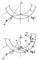
- Figure 1 shows, according to the prior art, how is carried out on a metal tube 1 devoid of ribs the search for defects on the outer wall.
- An ultrasonic transceiver transducer emits an ultrasonic beam of inclined axis, of an angle "i" with respect to the radius of the tube of axis X1 in the section plane of the figure.
- the tube is animated with respect to the transducer ER of a relative movement of rotation around its axis while sliding along this axis.
- an external longitudinal crack R is detected by an ultrasound beam from the transducer ER which carries out the course ABC in the wall of the tube with total reflection in B, part of the beam being returned to the transducer by the following defect R the CBA course.
- the amplitude of the signal corresponding to the fault R can be determined and compared with the amplitude of a standard fault kept in memory. It is then possible to eliminate the tubes whose cracks, detected by ultrasound, give signals of amplitude equal to or greater than a threshold corresponding to the amplitude of the signal given by the standard fault.
- Patent EP 0 294 955 describes a method for detecting faults in annular welds produced between a thin tube and a plug, both of the same metal.
- the method used does not relate to the detection of individualized defects but the detection of a set of very small defects such as multiple porosities formed in the welding area.
- This document does not describe any more than the Krautkrämer document the search for cracks on ribbed tubes and does not propose a method making it possible to identify individual defects such as cracks.
- Japanese patent 58-165 073 describes a particular device for correcting the amplitude of an ultrasound signal as a function of the distance traveled.
- ultrasonic detection means comprising at least one transceiver which emits a beam of ultrasound which penetrates into the wall of the tube; the beam is oriented in a plane perpendicular to the axis of travel of the tube with an angle of incidence making it possible to obtain good detection sensitivity.
- Any signal corresponding to the interception of a fraction of a fault is received by the receiver and processed by automatic electronic means with a view to comparing its amplitude with an amplitude threshold corresponding to a standard fault.
- the electronic automatic processing means determine beforehand the length of the round trip made by the ultrasound beam corresponding to each fault signal within the wall of the tube and provide a correction to the amplitude of the signal or that of the threshold before comparison; this fix depends on the difference that exists between the length of the path actually carried out by the signal and that of the path of the signal for which the threshold amplitude has been determined; if the difference between the two course lengths is zero, this fix is also zero.
- the comparison is then carried out in a known manner.
- the tube is animated with respect to the transceiver of a relative movement of rotation around its axis as well as of a movement of advance along this axis.
- the electronic means for automatic signal processing determine the route for each signal received, which the latter has actually achieved among the possible routes, by means of a measurement of the length of this course and carry out an amplitude correction corresponding to the course carried out in order to make correspond this amplitude of the signal to that which it would have had if it had carried out the course for which the amplitude of the threshold of comparison was planned.
- the electronic means for automatic processing of the signals after having determined for each signal received the path which the latter has actually carried out, by means of a measurement of the length of this route, perform a comparison of the amplitude of this signal with a threshold whose amplitude has been adjusted to take into account the length of the route actually achieved by this signal.
- this set of threshold amplitude values is stored in memory for use in the processing of signals.
- FIG. 1 represents a cross section of a tube of revolution without ribs which shows the conditions of detection of cracks on the internal or external walls of this tube by ultrasound.
- FIG. 2 represents a cross section of a tube of revolution, ribbed on the internal wall which shows the different possible paths of the ultrasound beam due to the presence of the ribs.
- FIG. 3 is a diagram of an embodiment of the automatic method according to the invention for evaluating defects detected by ultrasound.
- FIG. 1 shows, as was said above in the description of the state of the art, the conditions of use of an ER ultrasonic transceiver transducer for the detection of faults such as cracks longitudinal on the external or internal wall of a metal tube.
- the tube 2 has ribs such as N1, N2.
- the thickness "e2" to the right of the ribs is clearly greater, than the thickness "e1" between two ribs.
- the detection of an external longitudinal crack R1 can be carried out either by following the path A1 B1 C1, with reflection of the ultrasound beam at the top of the rib N1, or by following the path A1 B2 C2 clearly shorter with reflection on the inner wall between two ribs.
- the crack R1 being longitudinal and therefore parallel to the generatrices it will come in position C1 or C2 by sliding the tube along its axis X2, the ribs such as N1, N2, being helical.
- the longitudinal cracks R2, R3, formed on the internal wall of the tube can be between the ribs, or on one of them, or, if they are long enough, straddling ribs.
- the ultrasound signals corresponding to faults such as R1, R2, R3 are processed by automatic electronic means, not shown to which the ER transducer is connected to determine in a first phase for each signal received the length of the round trip made by the ultrasound beam.
- a comparison of these journey lengths with the actual lengths of the possible journeys which are the four return journeys A1 B1 C1, A1 B2 C2, A1 B1 and A1 B2, indicated in FIG. 2, makes it possible to classify these signals each in a corresponding category. to one of these courses. It is then possible to compare each signal with a reference threshold corresponding to a standard fault, by adjusting the amplitude of the signal or else the height of the threshold, in order to take into account the length of the path actually traveled by the ultrasound beam. associated with this signal.
- Such a comparison then makes it possible to determine, independently of the path traveled by the ultrasonic beam generating the signal, whether the detected fault is greater or not than the standard fault to which the comparison threshold corresponds.
- FIG. 3 is a diagram which shows the logical sequence of automatic operations for evaluating faults by the method according to the invention using electronic processing means known in themselves. It can be seen that the length of the signal path is compared at 11 with the path A1 B1. If there is equality an addition of n1 dB is made to the amplitude of the signal, before comparison of this corrected amplitude AC with the amplitude of the threshold S1 of acceptance or refusal. If the path length of the signal is not A1 B1 there is again a comparison in 12 with A1 B2 and possibly in 13 with A1 B1 C1. Corrective additions n2 dB and n3dB are added respectively.
- the signal path is A1 B2 C2 provided that the amplitude of threshold is determined for a standard fault whose signal amplitude is itself adjusted to correspond to such a path, no addition is to be made.
- the different amplitude corrections of the ultrasound signals such as n1dB, n2dB, n3dB are preferably determined by comparing the amplitudes of the ultrasound signals obtained according to the different possible paths of the ultrasound beam through the wall of the tube. .
Landscapes
- Physics & Mathematics (AREA)
- General Health & Medical Sciences (AREA)
- Immunology (AREA)
- Chemical & Material Sciences (AREA)
- Analytical Chemistry (AREA)
- Biochemistry (AREA)
- Health & Medical Sciences (AREA)
- General Physics & Mathematics (AREA)
- Life Sciences & Earth Sciences (AREA)
- Pathology (AREA)
- Acoustics & Sound (AREA)
- Engineering & Computer Science (AREA)
- Signal Processing (AREA)
- Investigating Or Analyzing Materials By The Use Of Ultrasonic Waves (AREA)
- Investigating Or Analyzing Materials By The Use Of Magnetic Means (AREA)
Claims (6)
- Verfahren zur Feststellung von Fehlern an den Außen- oder Innenwänden eines Metallrohrs (2) mit einer Drehaußenwand, umfassend spiralförmig verlaufende Innenrippen (N1, N2), bei dem Ultraschallerfassungsvorrichtungen mit mindestens einem Sendeempfänger (ER) eingesetzt werden, der einen Ultraschallstrahl aussendet, der in die Rohrwand eindringt, und der, wenn ein Teil dieses Strahls von einem Fehler (R1, R2, R3) reflektiert wird, ein diesem entsprechendes Signal empfängt, und umfassend außerdem Vorrichtungen zur elektronischen Verarbeitung dieser Signale, die es ermöglichen, ihre Amplitude automatisch mit einem Schwellenwert (S1) zu vergleichen, der einem Vergleichsfehler entspricht, dadurch gekennzeichnet, daß, nachdem das empfangene Signal in der Rohrwand Hin- und Rückwege (A1B1, A1B2, A1B1C1, A1B2C2) unterschiedlicher Länge zurückgelegt haben kann, die elektronischen Verarbeitungsvorrichtungen die Länge des jedem Signal entsprechenden, von dem Strahl zurückgelegten Hin- und Rückwegs bestimmen und eine Korrektur der Amplitude des Signals oder des Schwellenwerts vor dem Vergleich vornehmen, eine Korrektur, die von dem Unterschied zwischen dem von dem Signal tatsächlich zurückgelegten Weg und dem Weg dieses Signals, für den die Amplitude des Schwellenwerts (S1) bestimmt wurde, abhängt.
- Verfahren nach Anspruch 1, dadurch gekennzeichnet, daß die elektronischen Bearbeitungsvorrichtungen für jedes empfangene Signal die Länge des Hin- und Rückwegs (A1B1, A1B2, A1B1C1, A1B2C2) bestimmen, den dieses von den möglichen Wegen tatsächlich zurückgelegt hat, und eine Amplitudenkorrektur vornehmen (n1dB, n2dB, n3dB), die dem zurückgelegten Weg entspricht, um die Amplitude (AC) des Signals derjenigen anzugleichen, die es gehabt hätte, wenn es den Weg zurückgelegt hätte, für den die Amplitude (S1) des Vergleichsschwellenwerts vorgesehen war.
- Verfahren nach Anspruch 1, dadurch gekennzeichnet, daß die elektronischen Verarbeitungsvorrichtungen für jedes empfangene Signal die Länge des Hin- und Rückwegs (A1B1, A1B2, A1B1C1, A1B2C2) festlegen, den dieses tatsächlich zurückgelegt hat, und einen Vergleich der Amplitude dieses Signals mit einem Schwellenwert vornehmen, dessen Amplitude angeglichen wurde, um der Länge des tatsächlich von diesem Signal zurückgelegten Wegs Rechnung zu tragen.
- Verfahren nach Anspruch 3, dadurch gekennzeichnet, daß die elektronischen Verarbeitungsvorrichtungen gespeichert Vergleichsschwellenwerte aufweisen, deren Amplitude für jede Hin- und Rückweglänge (A1B1, A1B2, A1B1C1, A1B2C2) angeglichen wurde, die von jedem Signal zurückgelegt werden kann, um die Amplitude jedes Signals mit dem Vergleichsschwellenwert zu vergleichen, welcher der Weglänge dieses Signals entspricht.
- Verfahren nach einem der Ansprüche 1 bis 4, dadurch gekennzeichnet, daß das Rohr (2) bezüglich dem Sendeempfänger (ER) eine relative Drehbewegung um seine Achse (X2) sowie eine Vorwärtsbewegung entlang dieser Achse macht.
- Verfahren nach einem der Ansprüche 1 bis 5, dadurch gekennzeichnet, daß die aufzuspürenden Fehler solche in Längs- oder Querrichtung sind.
Applications Claiming Priority (2)
| Application Number | Priority Date | Filing Date | Title |
|---|---|---|---|
| FR9006825 | 1990-05-28 | ||
| FR909006825A FR2662501B1 (fr) | 1990-05-28 | 1990-05-28 | Procede de detection de defauts sur des tubes metalliques a nervures helicouidales internes. |
Publications (2)
| Publication Number | Publication Date |
|---|---|
| EP0459920A1 EP0459920A1 (de) | 1991-12-04 |
| EP0459920B1 true EP0459920B1 (de) | 1995-07-19 |
Family
ID=9397173
Family Applications (1)
| Application Number | Title | Priority Date | Filing Date |
|---|---|---|---|
| EP91420167A Expired - Lifetime EP0459920B1 (de) | 1990-05-28 | 1991-05-27 | Verfahren zur Feststellung von Fehlern auf Metallrohren mit schraubenlinienförmig verlaufenden Innenrippen |
Country Status (7)
| Country | Link |
|---|---|
| US (1) | US5230247A (de) |
| EP (1) | EP0459920B1 (de) |
| JP (1) | JP3084082B2 (de) |
| AT (1) | ATE125360T1 (de) |
| DE (1) | DE69111307T2 (de) |
| ES (1) | ES2074245T3 (de) |
| FR (1) | FR2662501B1 (de) |
Families Citing this family (3)
| Publication number | Priority date | Publication date | Assignee | Title |
|---|---|---|---|---|
| US5377237A (en) * | 1993-04-05 | 1994-12-27 | General Electric Company | Method of inspecting repaired stub tubes in boiling water nuclear reactors |
| US7146524B2 (en) * | 2001-08-03 | 2006-12-05 | Isilon Systems, Inc. | Systems and methods for providing a distributed file system incorporating a virtual hot spare |
| US9784627B2 (en) | 2013-11-27 | 2017-10-10 | Panasonic Intellectual Property Management Co., Ltd. | Load sensor, load detector including load sensor, and method for detecting load |
Family Cites Families (11)
| Publication number | Priority date | Publication date | Assignee | Title |
|---|---|---|---|---|
| DE2238130C3 (de) * | 1972-08-03 | 1980-10-09 | Krautkraemer, Gmbh, 5000 Koeln | Verfahren zur Ermittlung und Kompensation von unterschiedlichen Schallschwächungseigenschaften bei der Ultraschall-Werkstoffprüfung |
| US4016750B1 (en) * | 1975-11-06 | 1994-04-05 | Stanford Research Inst | Ultrasonic imaging method and apparatus |
| US4056971A (en) * | 1976-05-10 | 1977-11-08 | Automation Industries, Inc. | Distance amplitude compensation system |
| GB1534366A (en) * | 1976-07-23 | 1978-12-06 | Emi Ltd | Signal processing arrangements |
| DE2636401C3 (de) * | 1976-08-11 | 1983-11-03 | Mannesmann AG, 4000 Düsseldorf | Verfahren zur automatischen Erkennung von Ultraschallanzeigen |
| US4098130A (en) * | 1977-03-11 | 1978-07-04 | General Electric Company | Energy reflection flaw detection system |
| JPS58165073A (ja) * | 1982-03-25 | 1983-09-30 | Mitsubishi Heavy Ind Ltd | 距離振巾補正回路 |
| US4524622A (en) * | 1982-07-20 | 1985-06-25 | Kabushiki Kaisha Kobe Seiko Sho | Method and apparatus of ultrasonic flaw detection |
| US4487072A (en) * | 1982-08-11 | 1984-12-11 | Livingston Waylon A | Ultrasonic testing of tubular goods |
| US4599900A (en) * | 1984-01-03 | 1986-07-15 | Automation Industries, Inc. | Workpiece for handling apparatus for nondestructive testing |
| FR2615288B1 (fr) * | 1987-05-12 | 1989-09-22 | Commissariat Energie Atomique | Procede automatique d'identification de defauts par ultrasons et systeme correspondant |
-
1990
- 1990-05-28 FR FR909006825A patent/FR2662501B1/fr not_active Expired - Fee Related
-
1991
- 1991-05-24 US US07/705,584 patent/US5230247A/en not_active Expired - Fee Related
- 1991-05-27 EP EP91420167A patent/EP0459920B1/de not_active Expired - Lifetime
- 1991-05-27 ES ES91420167T patent/ES2074245T3/es not_active Expired - Lifetime
- 1991-05-27 AT AT91420167T patent/ATE125360T1/de not_active IP Right Cessation
- 1991-05-27 DE DE69111307T patent/DE69111307T2/de not_active Expired - Fee Related
- 1991-05-27 JP JP03121395A patent/JP3084082B2/ja not_active Expired - Fee Related
Also Published As
| Publication number | Publication date |
|---|---|
| FR2662501B1 (fr) | 1994-11-18 |
| JP3084082B2 (ja) | 2000-09-04 |
| DE69111307D1 (de) | 1995-08-24 |
| FR2662501A1 (fr) | 1991-11-29 |
| EP0459920A1 (de) | 1991-12-04 |
| US5230247A (en) | 1993-07-27 |
| JPH0674942A (ja) | 1994-03-18 |
| ATE125360T1 (de) | 1995-08-15 |
| DE69111307T2 (de) | 1996-01-25 |
| ES2074245T3 (es) | 1995-09-01 |
Similar Documents
| Publication | Publication Date | Title |
|---|---|---|
| EP2577224B1 (de) | Produktionssteuerungsverfahren und vorrichtung zur überprüfung der traversierbarkeit von rohren | |
| EP0335808B1 (de) | Verfahren zur Plattierungsdickenkontrolle an metallischen Rohren mittels Ultraschall, dazugehörige Vorrichtung und Anwendung an plattierten Rohren in Zr-Legierung | |
| FR2480436A1 (fr) | Procede de detection de defauts par ultrasons | |
| US20020194916A1 (en) | Method for inspecting clad pipe | |
| NL1024726C2 (nl) | Werkwijze voor het controleren van een las tussen twee metalen pijpleidingen. | |
| FR2823852A1 (fr) | Procede pour detecter une fissure traversant la paroi d'un tube et mesurer la longueur de la fissure traversante | |
| CN112067696A (zh) | 一种基于激光超声检测管道表面缺陷的系统 | |
| CN109765296B (zh) | 厚壁管材内部缺陷超声检测三维定位方法 | |
| EP0459920B1 (de) | Verfahren zur Feststellung von Fehlern auf Metallrohren mit schraubenlinienförmig verlaufenden Innenrippen | |
| EP4095527B1 (de) | Verfahren und system zur ultraschalldetektion von internen defekten eines bauteils, insbesondere für ein luftfahrzeug | |
| EP0035423B1 (de) | Vorrichtung zur Detektion und Lokalisation von Oberflächendiskontinuitäten mit einem Lichtbündel | |
| FR2530342A1 (fr) | Procede et dispositif d'echographie ultrasonore | |
| EP1290435B1 (de) | Zerstörungsfreie ultraschallprüfung von liegenden fehlern in metallischen produkten | |
| JP3557553B2 (ja) | 溶接継手の超音波探傷試験方法 | |
| FR3142804A1 (fr) | Procédé de détection de fissure dans une conduite tubulaire | |
| JP4596325B2 (ja) | 内面フィン付き管の超音波探傷方法及び装置 | |
| FR3126156A1 (fr) | Procédé de reconstruction d’un profil d’épaisseur de pièce à contrôler | |
| CN103217485B (zh) | 一种斜探头超声场声压分布的测量试块 | |
| JP6953953B2 (ja) | 斜角超音波探傷の健全性評価方法、及びこれを用いた斜角超音波探傷方法 | |
| JPH0735729A (ja) | 溶接部の超音波探傷装置 | |
| NL2030748B1 (en) | Optical coherence tomography testing system | |
| CN203259509U (zh) | 一种斜探头超声场声压分布的测量试块 | |
| JP5505806B2 (ja) | 反射エコーの弁別方法 | |
| JP2003302381A (ja) | 超音波検査方法 | |
| JPS60162952A (ja) | 丸材の超音波探傷方法 |
Legal Events
| Date | Code | Title | Description |
|---|---|---|---|
| PUAI | Public reference made under article 153(3) epc to a published international application that has entered the european phase |
Free format text: ORIGINAL CODE: 0009012 |
|
| AK | Designated contracting states |
Kind code of ref document: A1 Designated state(s): AT DE ES IT |
|
| 17P | Request for examination filed |
Effective date: 19911223 |
|
| 17Q | First examination report despatched |
Effective date: 19931122 |
|
| GRAA | (expected) grant |
Free format text: ORIGINAL CODE: 0009210 |
|
| ITF | It: translation for a ep patent filed | ||
| AK | Designated contracting states |
Kind code of ref document: B1 Designated state(s): AT DE ES IT |
|
| REF | Corresponds to: |
Ref document number: 125360 Country of ref document: AT Date of ref document: 19950815 Kind code of ref document: T |
|
| REF | Corresponds to: |
Ref document number: 69111307 Country of ref document: DE Date of ref document: 19950824 |
|
| REG | Reference to a national code |
Ref country code: ES Ref legal event code: FG2A Ref document number: 2074245 Country of ref document: ES Kind code of ref document: T3 |
|
| PLBE | No opposition filed within time limit |
Free format text: ORIGINAL CODE: 0009261 |
|
| STAA | Information on the status of an ep patent application or granted ep patent |
Free format text: STATUS: NO OPPOSITION FILED WITHIN TIME LIMIT |
|
| 26N | No opposition filed | ||
| PGFP | Annual fee paid to national office [announced via postgrant information from national office to epo] |
Ref country code: AT Payment date: 20020417 Year of fee payment: 12 |
|
| PGFP | Annual fee paid to national office [announced via postgrant information from national office to epo] |
Ref country code: DE Payment date: 20020418 Year of fee payment: 12 |
|
| PGFP | Annual fee paid to national office [announced via postgrant information from national office to epo] |
Ref country code: ES Payment date: 20020522 Year of fee payment: 12 |
|
| PG25 | Lapsed in a contracting state [announced via postgrant information from national office to epo] |
Ref country code: AT Free format text: LAPSE BECAUSE OF NON-PAYMENT OF DUE FEES Effective date: 20030527 |
|
| PG25 | Lapsed in a contracting state [announced via postgrant information from national office to epo] |
Ref country code: ES Free format text: LAPSE BECAUSE OF NON-PAYMENT OF DUE FEES Effective date: 20030528 |
|
| PG25 | Lapsed in a contracting state [announced via postgrant information from national office to epo] |
Ref country code: DE Free format text: LAPSE BECAUSE OF NON-PAYMENT OF DUE FEES Effective date: 20031202 |
|
| REG | Reference to a national code |
Ref country code: ES Ref legal event code: FD2A Effective date: 20030528 |
|
| PG25 | Lapsed in a contracting state [announced via postgrant information from national office to epo] |
Ref country code: IT Free format text: LAPSE BECAUSE OF NON-PAYMENT OF DUE FEES Effective date: 20050527 |