EP0459928A1 - Einrichtung zur einphasigen Behandlung von Flüssigkeitsströmen in einem Kontaktapparat sowie zugehöriger Rückführungsentgaser - Google Patents
Einrichtung zur einphasigen Behandlung von Flüssigkeitsströmen in einem Kontaktapparat sowie zugehöriger Rückführungsentgaser Download PDFInfo
- Publication number
- EP0459928A1 EP0459928A1 EP91460033A EP91460033A EP0459928A1 EP 0459928 A1 EP0459928 A1 EP 0459928A1 EP 91460033 A EP91460033 A EP 91460033A EP 91460033 A EP91460033 A EP 91460033A EP 0459928 A1 EP0459928 A1 EP 0459928A1
- Authority
- EP
- European Patent Office
- Prior art keywords
- treatment
- flow
- installation according
- gas
- liquid
- Prior art date
- Legal status (The legal status is an assumption and is not a legal conclusion. Google has not performed a legal analysis and makes no representation as to the accuracy of the status listed.)
- Granted
Links
- 239000007788 liquid Substances 0.000 title claims abstract description 108
- 230000004907 flux Effects 0.000 title description 6
- 238000007872 degassing Methods 0.000 claims abstract description 16
- 239000007789 gas Substances 0.000 claims description 104
- 238000009434 installation Methods 0.000 claims description 60
- 238000004090 dissolution Methods 0.000 claims description 32
- 230000003134 recirculating effect Effects 0.000 claims description 23
- XLYOFNOQVPJJNP-UHFFFAOYSA-N water Substances O XLYOFNOQVPJJNP-UHFFFAOYSA-N 0.000 claims description 21
- 238000000034 method Methods 0.000 claims description 14
- CBENFWSGALASAD-UHFFFAOYSA-N Ozone Chemical compound [O-][O+]=O CBENFWSGALASAD-UHFFFAOYSA-N 0.000 claims description 12
- 238000002347 injection Methods 0.000 claims description 12
- 239000007924 injection Substances 0.000 claims description 12
- RAHZWNYVWXNFOC-UHFFFAOYSA-N Sulphur dioxide Chemical compound O=S=O RAHZWNYVWXNFOC-UHFFFAOYSA-N 0.000 claims description 10
- 239000000839 emulsion Substances 0.000 claims description 10
- CURLTUGMZLYLDI-UHFFFAOYSA-N Carbon dioxide Chemical compound O=C=O CURLTUGMZLYLDI-UHFFFAOYSA-N 0.000 claims description 8
- 238000011084 recovery Methods 0.000 claims description 7
- 239000003054 catalyst Substances 0.000 claims description 6
- 230000003068 static effect Effects 0.000 claims description 6
- 238000002156 mixing Methods 0.000 claims description 5
- 238000005507 spraying Methods 0.000 claims description 5
- 229910002092 carbon dioxide Inorganic materials 0.000 claims description 4
- 239000003153 chemical reaction reagent Substances 0.000 claims description 4
- 239000007787 solid Substances 0.000 claims description 4
- 238000003756 stirring Methods 0.000 claims description 4
- ZAMOUSCENKQFHK-UHFFFAOYSA-N Chlorine atom Chemical compound [Cl] ZAMOUSCENKQFHK-UHFFFAOYSA-N 0.000 claims description 3
- 239000003570 air Substances 0.000 claims description 3
- QVGXLLKOCUKJST-UHFFFAOYSA-N atomic oxygen Chemical compound [O] QVGXLLKOCUKJST-UHFFFAOYSA-N 0.000 claims description 3
- 239000001569 carbon dioxide Substances 0.000 claims description 3
- 239000000460 chlorine Substances 0.000 claims description 3
- 229910052801 chlorine Inorganic materials 0.000 claims description 3
- 229910052760 oxygen Inorganic materials 0.000 claims description 3
- 239000001301 oxygen Substances 0.000 claims description 3
- 238000012545 processing Methods 0.000 claims description 3
- 239000000203 mixture Substances 0.000 abstract description 11
- 238000006385 ozonation reaction Methods 0.000 abstract description 4
- 239000003651 drinking water Substances 0.000 abstract description 2
- 235000020188 drinking water Nutrition 0.000 abstract description 2
- 239000012071 phase Substances 0.000 description 39
- 238000012546 transfer Methods 0.000 description 10
- 238000004659 sterilization and disinfection Methods 0.000 description 6
- 238000010586 diagram Methods 0.000 description 5
- MHAJPDPJQMAIIY-UHFFFAOYSA-N Hydrogen peroxide Chemical compound OO MHAJPDPJQMAIIY-UHFFFAOYSA-N 0.000 description 4
- 238000000926 separation method Methods 0.000 description 4
- 238000013019 agitation Methods 0.000 description 3
- 238000013459 approach Methods 0.000 description 3
- 238000000265 homogenisation Methods 0.000 description 3
- 239000007791 liquid phase Substances 0.000 description 3
- 238000004519 manufacturing process Methods 0.000 description 3
- 241000894006 Bacteria Species 0.000 description 2
- 238000005276 aerator Methods 0.000 description 2
- 238000006243 chemical reaction Methods 0.000 description 2
- 238000013461 design Methods 0.000 description 2
- 238000009792 diffusion process Methods 0.000 description 2
- 238000009826 distribution Methods 0.000 description 2
- 230000000694 effects Effects 0.000 description 2
- 238000013213 extrapolation Methods 0.000 description 2
- 238000005188 flotation Methods 0.000 description 2
- 238000002513 implantation Methods 0.000 description 2
- 238000005086 pumping Methods 0.000 description 2
- 238000004513 sizing Methods 0.000 description 2
- 239000000243 solution Substances 0.000 description 2
- 239000000126 substance Substances 0.000 description 2
- 238000011144 upstream manufacturing Methods 0.000 description 2
- 239000002351 wastewater Substances 0.000 description 2
- 206010001526 Air embolism Diseases 0.000 description 1
- LSNNMFCWUKXFEE-UHFFFAOYSA-M Bisulfite Chemical compound OS([O-])=O LSNNMFCWUKXFEE-UHFFFAOYSA-M 0.000 description 1
- OKTJSMMVPCPJKN-UHFFFAOYSA-N Carbon Chemical compound [C] OKTJSMMVPCPJKN-UHFFFAOYSA-N 0.000 description 1
- KZBUYRJDOAKODT-UHFFFAOYSA-N Chlorine Chemical compound ClCl KZBUYRJDOAKODT-UHFFFAOYSA-N 0.000 description 1
- 241001080024 Telles Species 0.000 description 1
- 230000032683 aging Effects 0.000 description 1
- 238000012550 audit Methods 0.000 description 1
- 244000309464 bull Species 0.000 description 1
- 238000004364 calculation method Methods 0.000 description 1
- 229910052799 carbon Inorganic materials 0.000 description 1
- 230000003750 conditioning effect Effects 0.000 description 1
- 230000001276 controlling effect Effects 0.000 description 1
- 230000006378 damage Effects 0.000 description 1
- 238000000354 decomposition reaction Methods 0.000 description 1
- 238000004332 deodorization Methods 0.000 description 1
- 238000002845 discoloration Methods 0.000 description 1
- 230000009977 dual effect Effects 0.000 description 1
- 230000008030 elimination Effects 0.000 description 1
- 238000003379 elimination reaction Methods 0.000 description 1
- 230000001804 emulsifying effect Effects 0.000 description 1
- 239000007792 gaseous phase Substances 0.000 description 1
- 230000000977 initiatory effect Effects 0.000 description 1
- 238000012423 maintenance Methods 0.000 description 1
- 244000005700 microbiome Species 0.000 description 1
- 230000003647 oxidation Effects 0.000 description 1
- 238000007254 oxidation reaction Methods 0.000 description 1
- 238000005192 partition Methods 0.000 description 1
- 150000002978 peroxides Chemical class 0.000 description 1
- 239000011148 porous material Substances 0.000 description 1
- 239000000843 powder Substances 0.000 description 1
- 230000001105 regulatory effect Effects 0.000 description 1
- 238000001228 spectrum Methods 0.000 description 1
- 230000001131 transforming effect Effects 0.000 description 1
- 238000005406 washing Methods 0.000 description 1
- 239000003643 water by type Substances 0.000 description 1
Images


Classifications
-
- B—PERFORMING OPERATIONS; TRANSPORTING
- B01—PHYSICAL OR CHEMICAL PROCESSES OR APPARATUS IN GENERAL
- B01D—SEPARATION
- B01D53/00—Separation of gases or vapours; Recovering vapours of volatile solvents from gases; Chemical or biological purification of waste gases, e.g. engine exhaust gases, smoke, fumes, flue gases, aerosols
- B01D53/34—Chemical or biological purification of waste gases
- B01D53/74—General processes for purification of waste gases; Apparatus or devices specially adapted therefor
-
- C—CHEMISTRY; METALLURGY
- C02—TREATMENT OF WATER, WASTE WATER, SEWAGE, OR SLUDGE
- C02F—TREATMENT OF WATER, WASTE WATER, SEWAGE, OR SLUDGE
- C02F1/00—Treatment of water, waste water, or sewage
- C02F1/72—Treatment of water, waste water, or sewage by oxidation
-
- C—CHEMISTRY; METALLURGY
- C02—TREATMENT OF WATER, WASTE WATER, SEWAGE, OR SLUDGE
- C02F—TREATMENT OF WATER, WASTE WATER, SEWAGE, OR SLUDGE
- C02F1/00—Treatment of water, waste water, or sewage
- C02F1/72—Treatment of water, waste water, or sewage by oxidation
- C02F1/76—Treatment of water, waste water, or sewage by oxidation with halogens or compounds of halogens
- C02F1/763—Devices for the addition of such compounds in gaseous form
-
- C—CHEMISTRY; METALLURGY
- C02—TREATMENT OF WATER, WASTE WATER, SEWAGE, OR SLUDGE
- C02F—TREATMENT OF WATER, WASTE WATER, SEWAGE, OR SLUDGE
- C02F1/00—Treatment of water, waste water, or sewage
- C02F1/72—Treatment of water, waste water, or sewage by oxidation
- C02F1/78—Treatment of water, waste water, or sewage by oxidation with ozone
-
- Y—GENERAL TAGGING OF NEW TECHNOLOGICAL DEVELOPMENTS; GENERAL TAGGING OF CROSS-SECTIONAL TECHNOLOGIES SPANNING OVER SEVERAL SECTIONS OF THE IPC; TECHNICAL SUBJECTS COVERED BY FORMER USPC CROSS-REFERENCE ART COLLECTIONS [XRACs] AND DIGESTS
- Y10—TECHNICAL SUBJECTS COVERED BY FORMER USPC
- Y10S—TECHNICAL SUBJECTS COVERED BY FORMER USPC CROSS-REFERENCE ART COLLECTIONS [XRACs] AND DIGESTS
- Y10S261/00—Gas and liquid contact apparatus
- Y10S261/42—Ozonizers
Definitions
- the field of the invention is that of the treatment of liquids. More specifically, the invention relates to bringing liquids, and in particular drinking water or waste water, into contact with a treatment gas.
- a particular example of application of the invention is the ozonization of liquids.
- the invention also relates to the treatment of gases with transfer water.
- the invention can be applied to numerous fields where it is necessary to ensure contact of a fixed minimum duration between a liquid phase and a gas phase.
- the installation of the invention makes it possible to treat any type of liquid with any type of gas, for example oxygen, chlorine, carbon dioxide, or sulfur dioxide.
- gases for example oxygen, chlorine, carbon dioxide, or sulfur dioxide.
- transfer liquids such as, in particular, H2S, NH3, SO2 + water.
- the treatment medium is two-phase, that is to say that it consists of a liquid emulsion to be treated / treatment gas in the form of bubbles of variable sizes, generating turbulent flows.
- the purpose of the installation of the invention is to overcome these various drawbacks of the state of the art.
- an objective of the invention is to provide a method and an installation for treating a flow of liquid in which the operation of bringing a treatment gas to be used up into contact with the liquid to be treated is optimized.
- the invention aims to provide a high efficiency installation, in particular controlling hydrodynamic movements.
- a particular objective of the invention is to provide such an installation requiring a reduced and optimized volume of civil engineering.
- Another objective of the invention is to provide a treatment installation with minimized time for the passage of the liquid to be treated in the reactors, while respecting the minimum contact times.
- the invention also aims to maximize and homogenize the operation of treating the liquid to be treated, in particular in the case of disinfection.
- Another objective of the invention is to take advantage of the characteristics of current installations, in which there is no longer any problem of pressure drop. Indeed, in current installations, there is generally a double ozonation, which requires a pumping. It is therefore not a handicap to dimension this pumping down so as to accept additional pressure drops in the treatment chain. The design of the invention is therefore compatible with these requirements.
- the device of the invention will have the possibility of integrating into the piezometric line of an existing installation.
- a particular objective of the invention is to provide a device for Forced dissolution of a treatment gas in a liquid to be treated, producing a single-phase treatment medium, which can in particular be used in the installation of the invention, but also in many other treatment chains.
- the invention also aims to provide such an installation, intended for the treatment of a gas with a transfer liquid.
- the treatment of liquids is thus divided into three separate successive stages, the addition of gas to the liquid, the additional dissolution and degassing, corresponding in particular to the initiation of the reaction, and the main reaction in a piston-type reactor. It is necessary to clearly distinguish and separate these three phases, in particular so that no disturbance comes to interfere in the contact phase.
- degassing is meant the separation of the gaseous and liquid phases, and obtaining a single-phase medium. On the other hand, this does not in any way mean stripping of the dissolved gas, the opposite result to that desired.
- the intermediate stage of forced dissolution produces a homogeneous and monophasic treatment medium, which ensures piston flow in the contactor means, the volume of which can then be reduced, compared with the prior art.
- all known installations carry out the contact phase on a two-phase medium, which causes turbulent flow.
- the invention provides a solution to a new problem, never posed in the prior art, namely obtaining a single-phase treatment medium, generating a flow in piston.
- monophasic medium is understood to mean both truly monophasic medium and quasi-monophasic medium, that is to say that may include micro-bubbles of gas, not disturbing the flow in the piston.
- the installation of the invention can also be applied to the treatment of a gas with a liquid.
- said means for injecting the treatment gas comprise at least one static mixer and / or at least one injector, for example of the venturi injector type.
- said chambers consist of a first central chamber forming a chimney, surrounded by a second annular chamber.
- recirculating devices are already known in themselves, and described for example in the American patent document US-4,072,613 in the name of ALIG. However, the role of these known devices and very distant from that of the device of the invention. Indeed, these recirculators are used alone for ozonation, which therefore takes place in a two-phase medium. According to the invention, the recirculator is inserted between a mixer and a contactor, and with the specific objective of transforming a gas-liquid emulsion into a single-phase medium.
- Said separation wall of the chambers advantageously has openings for crossing portions of said flow of the treatment medium.
- At least one of said chambers comprises means for forced recirculation of said treatment medium in said direction of recirculation and / or dynamic dissolution of said treatment gas in the treatment medium, in particular by spraying gas bubbles present in the treatment medium.
- At least one of said chambers comprises means of forced stirring of the upper surface of said treatment medium so as to cause the recovery and recirculation of the degassing vents of said device and / or spraying the process gas bubbles.
- Said forced recirculation means and / or said stirring means are advantageously constituted by a mechanically or otherwise driven propeller, situated in said central chamber forming a chimney.
- One or more propellers can also be placed in the annular chamber.
- the placement of a propeller takes into account in particular the direction of flow flow in the recirculating device, the location of the injection means (injection into the central chimney or the annular chamber, at the upper or lower level of the recirculating device), and the main objective of the propeller (to favor the recirculation of the liquid and gaseous flows, or to favor the exhaustion of the gases, by spraying gas bubbles and the homogenization of the mixture).
- the propeller in particular intended to improve degassing and homogenization, is driven in counter-rotation with respect to the direction of circulation of the treatment medium. This allows in particular the spraying of gas bubbles which rise to the surface, and therefore increases the rate of dissolution of the treatment gas.
- This recirculator-degasser device may also include means for adding a reagent to said flow of liquid to be treated, such as a solid or liquid catalyst, coupled with a physical process, for example of the ultraviolet type.
- a reagent such as a solid or liquid catalyst, coupled with a physical process, for example of the ultraviolet type.
- the contact time of said flow of liquid with said treatment gas in said recirculating device is less than 60 seconds.
- said contactor means comprise means for injecting said undissolved treatment gas recovered in said upper part of the recirculating device, and / or fresh treatment gas, subject to means for maintaining the quality of water at the end treatment.
- These contacting means may in particular comprise at least one substantially vertical dissolution column, in which said liquid circulates from top to bottom, said column comprising in its upper part a chamber for continuously introducing said treatment gases.
- said column also comprises a suction propeller driven in rotation in the direction of circulation of said liquid, and optionally locally a central wall cooperating with said propeller so as to form a recirculation device.
- Such an installation may advantageously comprise means for treating a predetermined fraction of the total flow of liquid to be treated, said means for treating a fraction of a flow cooperating with means for mixing in line in a turbulent zone of said fraction of the flow being treated with the rest of the flow.
- the installation comprises at least two devices comprising adding means, a recirculating device and contactor means, mounted in parallel on the same pipe for the liquid to be treated, and means for selecting the number of said active devices, as a function of the volume of liquid to be treated.
- Said treatment gas can in particular belong to the group comprising ozone, ozonated air, oxygen, sulfur dioxide, carbon dioxide and chlorine.
- the object of the invention is therefore to provide a treatment method making contact between the liquid to be treated and the treatment gas in a medium monophasic, so as to limit the volume of the installations, ensuring a flow in piston.
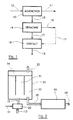
- the basic principle of the invention consists in effecting the operation of treating liquids in three stages, as illustrated in FIG. 1, which presents the process of the invention in the form of a flowchart.
- the treatment of a gas to be treated takes place in a similar manner.
- the first step 10 is a step of adding a treatment gas 11 to the liquid to be treated 12, or transfer. This step results in the production of a gas / liquid emulsion 13.
- the treatment rate and the concentration of the gas associated with the liquid to be treated can be variable depending on the quality of the liquid to be treated and / or the desired concentration of gas dissolved in the liquid.
- the liquid can optionally also receive prior chemical conditioning upstream of the recirculator.
- the second step 14 comprises an additional dissolution and degassing allowing the elimination of the gas during the transfer 10.
- This degassing 14 that is to say in particular the recovery of the vents, thus makes it possible to subsequently treat not a medium two-phase (gas + liquid), heterogeneous flow generator, but a truly single-phase medium (liquid + dissolved gas).
- the vents 16 can optionally be recovered, confined and reinjected downstream (17).
- the last step 18 is a phase of single-phase contact of the liquid with the dissolved gas.
- this phase there may be regulation of the rate of treatment gas as a function of the quality of the treated liquid 19.
- the invention physically achieves the separation of the treatment in two essential steps (transfer 10 and contact 18). This separation makes it possible to envisage the realization of installations of reduced size, and therefore to better control, in addition to the problems of civil engineering, hydrodynamics. Furthermore, the intermediate degassing phase 14 makes it possible to work in single-phase hydraulics during the contact step 18.
- FIG. 2 The general diagram of an installation for treating liquids or gases according to the principle of the invention is shown in FIG. 2.
- the liquid to be treated is water, and for example water to be disinfected, and the gas for treating ozone or ozonated air.
- the reagent is of the solid type (powder, carbon, catalyst, etc.) or liquid (bisulfite, peroxide, hydrogen peroxide, etc.).
- the add-on module 20, or transferer produces a gas-liquid emulsion 13, that is to say a two-phase mixture, as homogeneous as possible, comprising the liquid 12 with bubbles of dissolved gas.
- the emulsion 13 is introduced into the module 30 for forced dissolution, which essentially aims to transfer the ozone, or any other treatment gas, into the liquid to be treated and to provide a liquid single-phase medium 15 at the outlet of the module 30
- It may in particular be a recirculating device, comprising a exhaust chimney 31, a degassing vent 32, and an annular chamber 33 of forced recirculation coxial with the exhaust chimney 31.
- the recirculation aims to ensure sufficient contact of all the water to be treated with ozone, and to dissolve as much ozone as possible.
- the single-phase treatment medium 15 is then transmitted to the contactor module 40, which provides sufficient water-ozone contact time, in particular with regard to the standards in force, and supplies the treated liquid 19 as an output.
- the various pipes connecting the modules 20, 30 and 40 can be of any cross section, for example cylindrical, ovoid, rectangular or trapezoidal. Likewise, these different modules 20, 30 and 40 can be of any cross section.
- the add-on module 20 is preferably of the static mixer type or of the venturi type injector.
- Static mixers are devices with high shear rate, which can treat all or part of the volume of water. These devices, of known type, are in the form of a pipe containing a series of fixed propellers, with opposite pitch, of Archimedes screw, or any other type of immobile element implanted in a pipe, ensuring the division of the current flowing in this pipe, and forming a desired hydraulic singularity.
- Venturi type injectors allow the same type of contact to be made as a static mixer, but a priori with a lower pressure drop.
- a downflow motor venturi is used, so as to combine the emulsifying effect and the effect of bubble column downwardly co-current.
- the add-on module 20 can comprise a static mixer and a venturi injector in series, the injector being placed upstream or downstream of the mixer.
- the liquid emulsion 13 to be treated-treatment gas is then introduced into a module 30 for forced dissolution.
- This module 30 can in particular be of the recirculator or recirculation column type, as shown in section in FIGS. 3 and 4, so as to allow the recirculation of the vents and the exhaustion of the gas.
- This recirculating device 30 can for example be of cylindrical section, or parallelepiped.
- This recirculator 30 comprises a chamber or a chimney 31 for exhaustion of gases and an annular chamber 33 for forced recirculation coxial with the chimney 31 for exhaustion.
- the two chambers 31 and 33 are separated by a wall 39, and communicate with each other at their lower 34 and upper 35 parts, so as to allow the recirculation of the treatment medium in the recirculator.
- the purpose of this device 30 is to dissolve as much treatment gas as possible in the liquid to be treated and to homogenize the treatment medium. It also makes it possible to eliminate gas bubbles, and therefore to produce a single-phase medium, facilitating piston flow and avoiding problems of flotation, or gas embolism, on filters downstream.
- vents 36 can be recovered (32), and reinjected at the level of the contactor 40.
- the evacuation of the single-phase treatment medium can be done at the bottom (37 A , 37 B ) of the recirculator, or as shown in FIG. 4, on the external vertical wall (38 A , 38 B ) of the recirculator.
- This evacuation can in particular be carried out by means of orifices, crowns, and / or strainers.
- FIG. 5 shows an alternative embodiment of a recirculator, in which the injection of the emulsion 13 is made at the level of the crown.
- the direction of recirculation goes from the annular chamber 32 to the central chimney 31.
- the evacuation 37 of the single-phase treatment medium will then be at the center of the bottom of the recirculator.
- the wall 39 will advantageously be pierced with openings, or made up of several sections, creating small recirculation cells.
- the recirculator can be equipped with means for forced recirculation of the treatment medium, as illustrated in FIG. 6.
- a driven propeller 50, or a turbine, placed in the central chimney 31 in the sense of movement, ensures better circulation of the treatment medium. It also makes it possible to improve the dissolution of the treatment gas, by breaking the gas bubbles, that is to say by reducing their size, and by facilitating their recirculation.
- Forced recirculation means can also be placed in the annular chamber 33.
- the propeller 50 will be placed so as to ensure agitation of the upper part of the treatment medium, allowing the recovery of vents, and therefore an increase in the rate of dissolved gas.
- This result can also be obtained by means of agitation of the surface which does not disturb the recirculation, such as, for example, beaters.
- the speed of rotation of the propeller or of the turbine is advantageously linked to the hydraulic conditions. More precisely, the position and the speed of rotation of the turbine will be fixed as a function of the energy cost / suction efficiency compromise.
- the turbine being positioned, one can act on the speed of rotation so as to be in the suction conditions of the gaseous sky, thus allowing the recovery of the vents.
- the recirculator also comprises means for adding one or more reagents to the treatment medium, for example of the catalyst type.
- They can in particular be solid or liquid catalysts, such as hydrogen peroxide.
- a catalyst is advantageously coupled with a process physical, for example of the ultraviolet type.
- the recirculator will have a height H of approximately 4 m, for a diameter D N of the order of 1 m.
- Such a recirculator-degasser device 30 clearly finds numerous applications in other industrial processes, requiring the mixing of a gas and a liquid in a single liquid phase.
- the single-phase treatment medium 15 is directed towards the contactor means 40, which ensure a minimum contact time between the liquid to be treated and the dissolved treatment gas.
- obtaining a single-phase medium makes it possible to produce a piston flow, and therefore to reduce the contact time of the treatment medium and, consequently, civil engineering.
- the contactor means 40 may be baffled tanks, as shown in FIGS. 8 and 9. These tanks include a set of partitions 41 A , 41 B , 41 C , 41 D , defining, by means of openings 42 A , 42 B , 42 C , 42 D , alternately in the up and down position, a compulsory path for the entire flow of liquid. The travel time of this path corresponds to the imposed contact time.
- the flow being of piston type, each liquid molecule has an identical contact time, corresponding for example to the minimum time imposed by the standards.
- the contactor means 40 are positioned either concentrically (FIG. 8) around the recirculating device 30, or asymmetrically (FIG. 9), or even symmetrically, or in any other way, taking account in particular of space constraints.
- contactor 40 It is also possible to use as contactor 40 a single pipe, or a network of pipes in parallel, stacked or stacked. It is then necessary to work in turbulent regime, so as to obtain a flat speed profile. We will also try to avoid elbows as much as possible. Such a configuration has the advantage of requiring only a small investment.
- FIG. 10 is the diagram of contactor means comprising means 43 for re-injecting the vents. It is also possible to inject fresh treatment gas 44, that is to say not already used, so as to optimize the quality of the water, and / or in the case where a step treatment is more advantageous.
- the contactor means are separated into at least two tanks 40 A and 40 B (or pipes or series of pipes), and an injection device 43 is installed between the tanks 40 A and 40 B.
- This injection device is for example of the porous type or surface aerator, such as a beater. This injection can be made either at ground level or at sky level.
- a small volume compartment will be used, characterized geometrically so as to have no bubbles or micro-bubbles (flotation) downstream.
- the volume of this compartment will for example correspond to a passage time of the order of 30 seconds.
- FIG. 8 comprises an injection device (optional) of the surface aerator type.
- the injection is carried out in column 54, in which the liquid to be treated circulates from top to bottom.
- the treatment gas 53 is continuously introduced into the upper part of this column, and is sucked into the liquid to be treated.
- forced suction means such as a propeller 51 driven in the direction of circulation of the liquid, can be added.
- a propeller 51 driven in the direction of circulation of the liquid.
- a central wall 52 can be placed concentrically inside the column 54, over at least part of the length of this column.
- the movement of the propeller 51 in this case causes a recirculation of part of the liquid to be treated, from the interior of the chamber defined by the wall 52 to the annular chamber formed by this wall and the column 54.
- Others configurations of such a recirculator device can be envisaged (arrangements of one or more propellers in the central chamber or the annular chamber, days in the wall 52, ...) as has already been presented for the main recirculator 30 of the invention, in conjunction with Figures 3 to 6.
- the quantity of gas 53 reinjected will depend on the water quality at the end of treatment and / or the desired dissolved gas concentration.
- means 45 for regulating the quantity of gas controls the injector 43.
- the gas reinjection can be done in one or more stages. It is thus possible to inject gases 53 by means of two successive injectors, interposed between tanks or pipes. This configuration makes it possible to reduce the concentration of gas entering the injector 41, and to obtain good energy efficiency, in particular when the quality of the liquid to be treated is good and substantially constant.
- these devices can be mounted in parallel, or in cascade.
- Another essential advantage of this configuration is the possibility of selecting the number of devices to be implemented, as a function of the total water flow rate of the pipeline at each instant. Thus, we will work in each device at nominal water flow rate, avoiding the risks of laminar flows, when a contactor receives a too low water flow rate.
- a too low flow rate would prevent, in the recirculator, the recirculation of the gas bubbles. Indeed, in a mixture comprising bubbles and water, recirculation is easier for the liquid than for the gas bubbles.
- Such an installation can also treat only a fraction of the total flow to be treated, the fraction being withdrawn by a bypass. After treatment, the treated medium is then mixed with the rest of the flow, by means of mixing in line in a turbulent area.
- the value of the fraction treated can be variable, and chosen as a function of the quality of the water to be treated, or of the desired quality of treatment.
Landscapes
- Engineering & Computer Science (AREA)
- Chemical & Material Sciences (AREA)
- Environmental & Geological Engineering (AREA)
- Organic Chemistry (AREA)
- Life Sciences & Earth Sciences (AREA)
- Water Supply & Treatment (AREA)
- Hydrology & Water Resources (AREA)
- Oil, Petroleum & Natural Gas (AREA)
- Chemical Kinetics & Catalysis (AREA)
- Biomedical Technology (AREA)
- General Chemical & Material Sciences (AREA)
- Analytical Chemistry (AREA)
- Health & Medical Sciences (AREA)
- Degasification And Air Bubble Elimination (AREA)
- Treatment Of Water By Oxidation Or Reduction (AREA)
- Physical Water Treatments (AREA)
- Physical Or Chemical Processes And Apparatus (AREA)
Applications Claiming Priority (2)
| Application Number | Priority Date | Filing Date | Title |
|---|---|---|---|
| FR9006969A FR2662616B1 (fr) | 1990-05-31 | 1990-05-31 | Installation pour le traitement de flux liquides a contacteur monophasique, et dispositif recirculateur-degazeur pour une telle installation. |
| FR9006969 | 1990-05-31 |
Publications (2)
| Publication Number | Publication Date |
|---|---|
| EP0459928A1 true EP0459928A1 (de) | 1991-12-04 |
| EP0459928B1 EP0459928B1 (de) | 1995-05-03 |
Family
ID=9397287
Family Applications (1)
| Application Number | Title | Priority Date | Filing Date |
|---|---|---|---|
| EP91460033A Expired - Lifetime EP0459928B1 (de) | 1990-05-31 | 1991-05-29 | Einrichtung zur einphasigen Behandlung von Flüssigkeitsströmen in einem Kontaktapparat sowie zugehöriger Rückführungsentgaser |
Country Status (5)
| Country | Link |
|---|---|
| US (1) | US5399261A (de) |
| EP (1) | EP0459928B1 (de) |
| CA (1) | CA2043162C (de) |
| DE (1) | DE69109367D1 (de) |
| FR (1) | FR2662616B1 (de) |
Cited By (4)
| Publication number | Priority date | Publication date | Assignee | Title |
|---|---|---|---|---|
| FR2715395A1 (fr) * | 1994-01-26 | 1995-07-28 | Anjou Rech | Unité de traitement d'eau par ozonation, et installation de production d'eau ozonée correspondante. |
| DE4428147A1 (de) * | 1994-08-09 | 1996-02-15 | Bwt Wassertechnik Gmbh | Verfahren und Vorrichtung zur Trinkwasseraufbereitung |
| FR2836163A1 (fr) * | 2002-02-18 | 2003-08-22 | Air Liquide | Procede d'ozonation d'une phase liquide contenant des particules solides |
| WO2007055670A1 (fr) * | 2005-11-11 | 2007-05-18 | Eve Recycling Sarl | Procede de recyclage de solution de gravure pour le traitement des cartes imprimees |
Families Citing this family (10)
| Publication number | Priority date | Publication date | Assignee | Title |
|---|---|---|---|---|
| US5460731A (en) * | 1993-07-23 | 1995-10-24 | Aquatex Group Industrie, S.A. | Method of aeration of liquids |
| FR2767522B1 (fr) * | 1997-08-20 | 1999-10-01 | Air Liquide Sante Dev Sa | Procede et dispositif de traitement de l'eau par injection d'ozone et de dioxyde de carbone |
| US6503403B2 (en) | 2001-03-28 | 2003-01-07 | Lawrence M. Green | Gas-liquid contact apparatus |
| FR2823499B1 (fr) * | 2001-04-12 | 2004-02-27 | Vivendi Water Systems | Procede de remineralisation d'une eau brute |
| FR2836162B1 (fr) * | 2002-02-18 | 2004-05-07 | Air Liquide | Procede de traitement de papiers uses par l'ozone |
| US20030229738A1 (en) * | 2002-06-05 | 2003-12-11 | Dactron | Controller interface |
| CA2607713C (en) * | 2007-11-14 | 2009-05-26 | Dagua Inc. | Water treatment apparatus |
| US7771599B1 (en) * | 2009-03-09 | 2010-08-10 | Doosan Hydro Technology, Inc. | System and method for using carbon dioxide sequestered from seawater in the remineralization of process water |
| US10894731B2 (en) * | 2016-10-25 | 2021-01-19 | Ds Services Of America, Inc. | Ozone generator for water purification system |
| CN112499750A (zh) * | 2021-01-25 | 2021-03-16 | 河南弘康环保科技有限公司 | 一种去除效果良好的内循环臭氧催化氧化污水处理装置 |
Citations (7)
| Publication number | Priority date | Publication date | Assignee | Title |
|---|---|---|---|---|
| FR1062139A (fr) * | 1951-08-31 | 1954-04-20 | Procédé de désinfection de l'eau et installation pour la mise en oeuvre du procédé | |
| DE2045603A1 (de) * | 1969-09-17 | 1971-04-22 | Procedes Sem | Verfahren und Vorrichtung zur Ver mischung einer gasförmigen Phase mit einer flüssigen Phase |
| FR2247426A1 (en) * | 1973-10-11 | 1975-05-09 | Benckiser Wassertechnik Joh A | Elimination of nitrogenous material from water - by oxidising in presence of manganese and copper ions |
| US4072613A (en) * | 1976-10-04 | 1978-02-07 | The United States Of America As Represented By The Secretary Of The Navy | Ozone reactor for liquids |
| US4197200A (en) * | 1978-08-29 | 1980-04-08 | The United States Of America As Represented By The Secretary Of The Navy | Shipboard blackwater physical/chemical treatment system |
| FR2558818A1 (fr) * | 1984-01-19 | 1985-08-02 | Melyepitesi Tervezo | Procede et appareil pour le traitement de l'eau a l'aide d'ozone, prepare en partant de gaz riche en oxygene |
| FR2614016A1 (fr) * | 1987-04-16 | 1988-10-21 | Yoshida Yasunobu | Procede et appareil pour la purification de l'air et de l'eau |
Family Cites Families (34)
| Publication number | Priority date | Publication date | Assignee | Title |
|---|---|---|---|---|
| US1312754A (en) * | 1919-08-12 | Apparatus fob | ||
| US1342115A (en) * | 1916-01-27 | 1920-06-01 | Thomas A Janney | Flotation-machine |
| US1402099A (en) * | 1917-01-25 | 1922-01-03 | John T Shimmin | Flotation apparatus |
| US1434232A (en) * | 1921-04-18 | 1922-10-31 | George T Hanson | Method of mixing |
| US2530814A (en) * | 1945-10-12 | 1950-11-21 | Schenley Ind Inc | Apparatus for aerating liquids |
| US2684233A (en) * | 1951-12-07 | 1954-07-20 | Pearson M Payne | Froth flotation apparatus |
| US3092678A (en) * | 1958-04-29 | 1963-06-04 | Vogelbusch Gmbh | Apparatus for gasifying liquids |
| US3625834A (en) * | 1967-07-03 | 1971-12-07 | Mueller Hans | Method of mixing gaseous and liquid phases |
| CH466818A (fr) * | 1967-12-08 | 1968-12-15 | Pista Sa | Procédé de traitement d'un liquide au moyen d'un fluide gazeux et installation pour la mise en oeuvre de ce procédé |
| CH471892A (de) * | 1968-04-04 | 1969-04-30 | Mueller Hans | Verfahren und Anordnung zur Steuerung des Substratflusses zu und aus Fermentationsbehältern mit eingebauten rotierenden Werkzeugen für Mischung und Schaumabscheidung |
| US3605975A (en) * | 1969-03-03 | 1971-09-20 | Ray S Brimhall | Apparatus for processing bituminous sands |
| US3643403A (en) * | 1970-04-29 | 1972-02-22 | Richard E Speece | Downflow bubble contact aeration apparatus and method |
| CH527773A (de) * | 1971-08-13 | 1972-09-15 | Kaelin J R | Verfahren zur Eintragung von Sauerstoff in eine zu klärende Flüssigkeit und Einrichtung zur Durchführung des Verfahrens |
| CH529073A (de) * | 1971-09-02 | 1972-10-15 | Kaelin J R | Verfahren zur Eintragung und Umwälzung von Sauerstoff oder sauerstoffhaltigem Gas in eine zu klärende Flüssigkeit und Einrichtung zur Durchführung des Verfahrens |
| US3945918A (en) * | 1974-01-10 | 1976-03-23 | Airco, Inc. | Methods and apparatus for treating a liquid with a gas |
| US3972815A (en) * | 1975-01-09 | 1976-08-03 | United States Filter Corporation | Mixing apparatus |
| JPS5315706A (en) * | 1976-07-28 | 1978-02-14 | Matsushita Electric Ind Co Ltd | Communicaiton control unit |
| JPS5818141B2 (ja) * | 1978-09-22 | 1983-04-11 | 株式会社日立製作所 | 通気撹拌装置 |
| DE2844398C2 (de) * | 1978-10-12 | 1985-11-28 | Heinrich Frings Gmbh & Co Kg, 5300 Bonn | Verfahren und Vorrichtung zum Dispergieren eines Gases in einer Flüssigkeit |
| DE2936388A1 (de) * | 1979-09-08 | 1981-04-02 | Hoechst Ag, 6000 Frankfurt | Verfahren und vorrichtung zur verbesserung der mischguete fluessiger, insbesondere zaeher medien |
| CA1139463A (en) * | 1979-10-02 | 1983-01-11 | Jon G. Albertsson | Apparatus for contacting a liquid with a gas |
| US4519959A (en) * | 1982-04-14 | 1985-05-28 | Tatsuro Takeuchi | Gas-liquid contacting apparatus |
| US4454077A (en) * | 1982-07-08 | 1984-06-12 | Union Carbide Corporation | Process and apparatus for mixing a gas and a liquid |
| US4564457A (en) * | 1983-11-03 | 1986-01-14 | L'eau Claire Systems, Inc. | Upflow gas eductor induced air floatation separator |
| JPS6153119A (ja) * | 1984-08-21 | 1986-03-17 | Denki Kagaku Kogyo Kk | 易焼結性鉛含有複合酸化物粉末及びその製造方法 |
| DE3516027A1 (de) * | 1985-05-04 | 1986-11-06 | Huels Chemische Werke Ag | Ruehrsystem und verfahren zum begasen von fluessigkeiten |
| JPS63178833A (ja) * | 1986-10-21 | 1988-07-22 | ユニオン・カーバイド・コーポレーション | 液体内へガスを導入するための方法及び装置 |
| US4784775A (en) * | 1987-03-02 | 1988-11-15 | Ari Technologies, Inc. | Removal of hydrogen sulfide from sour water |
| US4956080A (en) * | 1987-08-03 | 1990-09-11 | Microlift Systems, Incorporated | High pressure oxygen-saturated water treatment apparatus |
| US4750994A (en) * | 1987-09-15 | 1988-06-14 | Hydrochem Developments Ltd. | Flotation apparatus |
| JP2568417B2 (ja) * | 1987-11-16 | 1997-01-08 | 海洋工業株式会社 | 貯水池等の深層曝気装置 |
| US4919849A (en) * | 1988-12-23 | 1990-04-24 | Union Carbide Industrial Gases Technology Corporation | Gas-liquid mixing process and apparatus |
| US5009816A (en) * | 1990-04-26 | 1991-04-23 | Union Carbide Industrial Gases Technology Corporation | Broad liquid level gas-liquid mixing operations |
| US5108662A (en) * | 1991-05-01 | 1992-04-28 | Union Carbide Industrial Gases Technology Corporation | Gas-liquid mixing process and apparatus |
-
1990
- 1990-05-31 FR FR9006969A patent/FR2662616B1/fr not_active Expired - Fee Related
-
1991
- 1991-05-21 US US07/703,799 patent/US5399261A/en not_active Expired - Fee Related
- 1991-05-23 CA CA002043162A patent/CA2043162C/en not_active Expired - Fee Related
- 1991-05-29 EP EP91460033A patent/EP0459928B1/de not_active Expired - Lifetime
- 1991-05-29 DE DE69109367T patent/DE69109367D1/de not_active Expired - Lifetime
Patent Citations (7)
| Publication number | Priority date | Publication date | Assignee | Title |
|---|---|---|---|---|
| FR1062139A (fr) * | 1951-08-31 | 1954-04-20 | Procédé de désinfection de l'eau et installation pour la mise en oeuvre du procédé | |
| DE2045603A1 (de) * | 1969-09-17 | 1971-04-22 | Procedes Sem | Verfahren und Vorrichtung zur Ver mischung einer gasförmigen Phase mit einer flüssigen Phase |
| FR2247426A1 (en) * | 1973-10-11 | 1975-05-09 | Benckiser Wassertechnik Joh A | Elimination of nitrogenous material from water - by oxidising in presence of manganese and copper ions |
| US4072613A (en) * | 1976-10-04 | 1978-02-07 | The United States Of America As Represented By The Secretary Of The Navy | Ozone reactor for liquids |
| US4197200A (en) * | 1978-08-29 | 1980-04-08 | The United States Of America As Represented By The Secretary Of The Navy | Shipboard blackwater physical/chemical treatment system |
| FR2558818A1 (fr) * | 1984-01-19 | 1985-08-02 | Melyepitesi Tervezo | Procede et appareil pour le traitement de l'eau a l'aide d'ozone, prepare en partant de gaz riche en oxygene |
| FR2614016A1 (fr) * | 1987-04-16 | 1988-10-21 | Yoshida Yasunobu | Procede et appareil pour la purification de l'air et de l'eau |
Cited By (7)
| Publication number | Priority date | Publication date | Assignee | Title |
|---|---|---|---|---|
| FR2715395A1 (fr) * | 1994-01-26 | 1995-07-28 | Anjou Rech | Unité de traitement d'eau par ozonation, et installation de production d'eau ozonée correspondante. |
| WO1995020543A1 (fr) * | 1994-01-26 | 1995-08-03 | Gie Anjou Recherche | Unite de traitement d'eau par ozonation, et installation de production d'eau ozonee correspondante |
| US5843307A (en) * | 1994-01-26 | 1998-12-01 | Gie Anjou Recherche | Unit for the treatment of water by ozonization, and a corresponding installation for the production of ozonized water |
| DE4428147A1 (de) * | 1994-08-09 | 1996-02-15 | Bwt Wassertechnik Gmbh | Verfahren und Vorrichtung zur Trinkwasseraufbereitung |
| FR2836163A1 (fr) * | 2002-02-18 | 2003-08-22 | Air Liquide | Procede d'ozonation d'une phase liquide contenant des particules solides |
| WO2003070648A3 (fr) * | 2002-02-18 | 2004-03-25 | Air Liquide | Procede d'ozonation d'une phase liquide contenant des particules solides |
| WO2007055670A1 (fr) * | 2005-11-11 | 2007-05-18 | Eve Recycling Sarl | Procede de recyclage de solution de gravure pour le traitement des cartes imprimees |
Also Published As
| Publication number | Publication date |
|---|---|
| CA2043162A1 (en) | 1991-12-01 |
| FR2662616B1 (fr) | 1994-07-08 |
| DE69109367D1 (de) | 1995-06-08 |
| FR2662616A1 (fr) | 1991-12-06 |
| EP0459928B1 (de) | 1995-05-03 |
| US5399261A (en) | 1995-03-21 |
| CA2043162C (en) | 1998-12-29 |
Similar Documents
| Publication | Publication Date | Title |
|---|---|---|
| EP0459928B1 (de) | Einrichtung zur einphasigen Behandlung von Flüssigkeitsströmen in einem Kontaktapparat sowie zugehöriger Rückführungsentgaser | |
| EP0741670B1 (de) | Wasserozonierungseinheit mit einer anlage zur erzeugung von ozoniertem wasser | |
| EP0498750B1 (de) | Anlage zum Mischen zweier fluider Phasen durch mechanisches Rühren, insbesondere für die Wasserbehandlung durch Übertragung von oxydierendem Gas und Verwendung einer solchen Anlage | |
| EP0670816B1 (de) | Anlage zur entfernung von mirko-schadstoffen aus rohwasser, insbesondere aus bohrspülwasser mittels ozon und wasserstoffperoxid | |
| EP2139818A2 (de) | Verfahren und vorrichtung zur reinigung flüssiger effluenzen | |
| EP1232122B1 (de) | Verfahren und vorrichtung zur reinigung von wässrigen abfällen durch katalytische oxidation | |
| FR2713220A1 (fr) | Installation de potabilisation de l'eau à membranes filtrantes immergées. | |
| CA2662763C (fr) | Procede et installation pour la mise en contact de l'ozone dans un flux de liquide, en particulier d'eau potable ou d'eau residuaire | |
| JPH04504080A (ja) | スラッジを安定化するための装置及び方法 | |
| EP0226495B1 (de) | Verfahren und Vorrichtung zum Bleichen von Papierpulpe | |
| WO2017134048A1 (en) | Ozone-based advanced oxidation process | |
| FR2762232A1 (fr) | Procede et dispositif pour la mise en contact de l'ozone dans des fluides a traiter, notamment de l'eau | |
| WO2003084652A2 (fr) | Procede et reacteur de mise en contact gaz/liquide par dispersion, et applications | |
| CN113302161B (zh) | 将流体喷射入液体的装置、清洁所述装置的方法以及流出物处理设备 | |
| CA2939691C (fr) | Procede et dispositif de dispersion de gaz dans un liquide | |
| JP2005052689A (ja) | 膜の洗浄方法および膜濾過装置 | |
| US20070034565A1 (en) | Method for treating a contaminated fluid | |
| FR2768718A1 (fr) | Installation pour le traitement par irradiations u.v. d'un liquide | |
| EP1888468B1 (de) | Verfahren zur behandlung von wasser, insbesondere trinkwasser, und wasserbehandlungsanlage | |
| JPH10165971A (ja) | 加圧型下方注入式多段オゾン接触槽とその制御方法 | |
| EP1931454B1 (de) | Verfahren zur durchführung von hybridoxidation und zum inkontaktbringen von flüssigkeiten | |
| WO2008147165A1 (fr) | Conception d'un réacteur gazosiphon à boucle externe (external-loop airlift reactor) pour le traitement des effluents liquides par electrocoagulation/electroflotation | |
| JP3523743B2 (ja) | 加圧型下方注入式オゾン接触槽とその制御方法 | |
| FR3114094A1 (fr) | Procede et installation de traitement de fluide | |
| FR2840237A1 (fr) | Bac de dissolution melangeur multi usages |
Legal Events
| Date | Code | Title | Description |
|---|---|---|---|
| PUAI | Public reference made under article 153(3) epc to a published international application that has entered the european phase |
Free format text: ORIGINAL CODE: 0009012 |
|
| AK | Designated contracting states |
Kind code of ref document: A1 Designated state(s): BE DE DK ES FR GB IT |
|
| 17P | Request for examination filed |
Effective date: 19920520 |
|
| 17Q | First examination report despatched |
Effective date: 19930225 |
|
| GRAA | (expected) grant |
Free format text: ORIGINAL CODE: 0009210 |
|
| AK | Designated contracting states |
Kind code of ref document: B1 Designated state(s): BE DE DK ES FR GB IT |
|
| PG25 | Lapsed in a contracting state [announced via postgrant information from national office to epo] |
Ref country code: IT Free format text: LAPSE BECAUSE OF FAILURE TO SUBMIT A TRANSLATION OF THE DESCRIPTION OR TO PAY THE FEE WITHIN THE PRESCRIBED TIME-LIMIT;WARNING: LAPSES OF ITALIAN PATENTS WITH EFFECTIVE DATE BEFORE 2007 MAY HAVE OCCURRED AT ANY TIME BEFORE 2007. THE CORRECT EFFECTIVE DATE MAY BE DIFFERENT FROM THE ONE RECORDED. Effective date: 19950503 Ref country code: GB Effective date: 19950503 Ref country code: ES Free format text: THE PATENT HAS BEEN ANNULLED BY A DECISION OF A NATIONAL AUTHORITY Effective date: 19950503 Ref country code: DK Effective date: 19950503 |
|
| PG25 | Lapsed in a contracting state [announced via postgrant information from national office to epo] |
Ref country code: BE Effective date: 19950531 |
|
| REF | Corresponds to: |
Ref document number: 69109367 Country of ref document: DE Date of ref document: 19950608 |
|
| PG25 | Lapsed in a contracting state [announced via postgrant information from national office to epo] |
Ref country code: DE Effective date: 19950804 |
|
| GBV | Gb: ep patent (uk) treated as always having been void in accordance with gb section 77(7)/1977 [no translation filed] |
Effective date: 19950503 |
|
| BERE | Be: lapsed |
Owner name: ANJOU RECHERCHE Effective date: 19950531 |
|
| PLBE | No opposition filed within time limit |
Free format text: ORIGINAL CODE: 0009261 |
|
| STAA | Information on the status of an ep patent application or granted ep patent |
Free format text: STATUS: NO OPPOSITION FILED WITHIN TIME LIMIT |
|
| 26N | No opposition filed | ||
| PGFP | Annual fee paid to national office [announced via postgrant information from national office to epo] |
Ref country code: FR Payment date: 19980529 Year of fee payment: 8 |
|
| PG25 | Lapsed in a contracting state [announced via postgrant information from national office to epo] |
Ref country code: FR Free format text: LAPSE BECAUSE OF NON-PAYMENT OF DUE FEES Effective date: 20000131 |
|
| REG | Reference to a national code |
Ref country code: FR Ref legal event code: ST |