EP0459960B1 - Schraubengewindekonstruktion - Google Patents
Schraubengewindekonstruktion Download PDFInfo
- Publication number
- EP0459960B1 EP0459960B1 EP91850122A EP91850122A EP0459960B1 EP 0459960 B1 EP0459960 B1 EP 0459960B1 EP 91850122 A EP91850122 A EP 91850122A EP 91850122 A EP91850122 A EP 91850122A EP 0459960 B1 EP0459960 B1 EP 0459960B1
- Authority
- EP
- European Patent Office
- Prior art keywords
- load bearing
- thread
- root
- screw structure
- bearing flank
- Prior art date
- Legal status (The legal status is an assumption and is not a legal conclusion. Google has not performed a legal analysis and makes no representation as to the accuracy of the status listed.)
- Expired - Lifetime
Links
- 230000000063 preceeding effect Effects 0.000 claims 4
- 238000005553 drilling Methods 0.000 description 6
- 238000009527 percussion Methods 0.000 description 6
- 238000010276 construction Methods 0.000 description 2
- 230000013011 mating Effects 0.000 description 2
- 208000013201 Stress fracture Diseases 0.000 description 1
- 238000007792 addition Methods 0.000 description 1
- 230000007423 decrease Effects 0.000 description 1
- 230000003247 decreasing effect Effects 0.000 description 1
- 238000012217 deletion Methods 0.000 description 1
- 230000037430 deletion Effects 0.000 description 1
- 238000005065 mining Methods 0.000 description 1
- 238000012986 modification Methods 0.000 description 1
- 230000004048 modification Effects 0.000 description 1
- 230000035515 penetration Effects 0.000 description 1
- 238000006467 substitution reaction Methods 0.000 description 1
- XLYOFNOQVPJJNP-UHFFFAOYSA-N water Substances O XLYOFNOQVPJJNP-UHFFFAOYSA-N 0.000 description 1
Images


Classifications
-
- F—MECHANICAL ENGINEERING; LIGHTING; HEATING; WEAPONS; BLASTING
- F16—ENGINEERING ELEMENTS AND UNITS; GENERAL MEASURES FOR PRODUCING AND MAINTAINING EFFECTIVE FUNCTIONING OF MACHINES OR INSTALLATIONS; THERMAL INSULATION IN GENERAL
- F16B—DEVICES FOR FASTENING OR SECURING CONSTRUCTIONAL ELEMENTS OR MACHINE PARTS TOGETHER, e.g. NAILS, BOLTS, CIRCLIPS, CLAMPS, CLIPS OR WEDGES; JOINTS OR JOINTING
- F16B33/00—Features common to bolt and nut
- F16B33/02—Shape of thread; Special thread-forms
-
- E—FIXED CONSTRUCTIONS
- E21—EARTH OR ROCK DRILLING; MINING
- E21B—EARTH OR ROCK DRILLING; OBTAINING OIL, GAS, WATER, SOLUBLE OR MELTABLE MATERIALS OR A SLURRY OF MINERALS FROM WELLS
- E21B17/00—Drilling rods or pipes; Flexible drill strings; Kellies; Drill collars; Sucker rods; Cables; Casings; Tubings
- E21B17/02—Couplings; joints
- E21B17/04—Couplings; joints between rod or the like and bit or between rod and rod or the like
- E21B17/042—Threaded
- E21B17/0426—Threaded with a threaded cylindrical portion, e.g. for percussion rods
Definitions
- This invention relates generally to a screw thread structure and in particular to an improvement of a screw thread structure disclosed in U.S. Patent No. 4,799,844.
- the root portion has been configured as a portion of a circle, tangentially adjoining the two flanks of successive thread turns.
- the stress concentration along the thread root is an inverse function of the radius of that circle, i.e., the larger the radius of the circle, the lower the stress concentration.
- the stress concentrations at the ends of the root, where the flanks of the adjacent thread turns tangentially adjoin the root become very high and thus provide starting points for crack propagation.
- the size of the radius defining the circular root curvature decreases below a minimum allowable value, the stress concentration becomes very high at the bottom of the root.
- circular root curvatures are confined to radii sizes falling between certain maximum and minimum limits, depending on such factors as thread pitch and the like.
- the present invention involves a screw structure comprising at least one thread extending helically in spaced thread turns about a longitudinal axis.
- the thread includes a load bearing flank, a non-load bearing flank, and a crest portion extending between the load bearing flank and the non-load bearing flank.
- a root extends between adjacent thread turns.
- the root as viewed in longitudinal section, has a curvature defined by portions of two axially overlapping ellipses interconnected by a flat.
- the ellipses tangentially adjoin respective ones of the load bearing flank and non-load bearing flank.
- the flat is oriented parallel to the axis and tangentially adjoins the ellipses.
- FIGS. 1 and 2 Depicted in FIGS. 1 and 2 is a conventional down hole percussion drill which includes a drill bit 10 mounted at the front end of a drill string.
- the drill string includes a threaded element in the form of a driver sub 12 which slides over a rear end of the drill bit and which is connected to the drill bit 10 by a spline connection, i.e., by external splines 14 on the drill bit and internal splines (not shown) on the driver sub 12.
- the drill bit 10 is thus constrained to rotate with the driver sub 12 but is capable of limited axial movement relative thereto.
- the driver sub 12 includes an external or male screw thread 16 which is connected by a screw thread to an internal or female screw thread 18 of a mating member in the form of a cylindrical case 20.
- a piston 22 Slidably disposed within the case 20 is a piston 22 which is axially reciprocated by a conventional mechanism in order to apply percussive forces to the rear end of the drill bit to enhance the penetration rate of the drill bit.
- An upper end of the case 20 is threadedly connected to a top sub (not shown), and the latter is threadedly connected to another component of the drill string, and so on.
- FIG. 3 A prior art thread construction in accordance with U.S. Patent No. 4,799,844 is depicted in FIG. 3.
- Each of the male and female threads 16, 18 is of identical construction and thus only the male thread 16 of the driver sub 12 is depicted in FIG. 3.
- That conventional thread 16 includes a non-load bearing flank surface 26, a load bearing flank surface 28, and a crest portion 30 extending between the load bearing and non-load bearing flanks.
- the crest 30 is flat and extends axially. In other words, the crest portion 30 extends between thread flanks 26, 28 straight and parallel to the longitudinal axis of the driver sub 12.
- a root 32 extends between adjacent thread turns.
- the root portion has a curvature defined by a portion of an ellipse, shown in phantom at 34.
- the ellipse has a major axis 36 and a shorter and perpendicular minor axis 38.
- the major axis extends axially, i.e., parallel to the longitudinal axis of the driver sub 12 and the minor axis of the ellipse extends radially, i.e., perpendicularly to the longitudinal axis.
- the non-load bearing flank 26 of the thread has a greater surface area than the load bearing flank 28. That is, the thread profile resembles, a typical reverse buttress thread profile. Alteratively, the thread could be shaped as a buttress thread wherein the load bearing flank 28 has a greater surface area than the non-load bearing flank 26.
- screw structure could instead comprise a multiple thread lead.
- the load bearing and non-load bearing flanks extend tangentially from the ellipse 34 at the root 32 straight to the crest portions 30.
- the non-load bearing flank 26 has an angular slope A extending axially away from the crest portion at approximately 30°
- the load bearing flank 28 has an angular slope B extending axially away from the crest portion at approximately 60°, although other suitable angles could be provided.
- the elliptical root 34 presents a larger equivalent radius than a circular root and thus provides a greater relief in stress concentration at the root. Also, the elliptical root is stronger than a circular root structure because of the greater wall thickness which remains after the elliptical root is formed. Furthermore, the elliptical root configuration allows for greater thread-to-thread contact between abutting load bearing flanks.
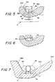
- FIGS. 4, 5 and 7 a still greater relief in stress concentration at the root is provided.
- FIGS. 4, 5 and 7 The items depicted in those figures are given the same reference numerals as corresponding elements in FIG. 3 together with the suffix "A".
- the thread 16A depicted in FIGS. 4, 5 and 7 is a reverse buttress type thread of the same general nature as described in connection with FIG. 3. That is, the thread has load bearing and non-load bearing flanks 26A, 28A interconnected by flat crest portions 30A, and a root 39 which tangentially joins those flanks.
- the present invention is also applicable to other thread configurations, including buttress threads.
- the root 39 is not of continuously curved configuration as is the case with the root depicted in FIG. 3. Rather, the root 39 is, in accordance with the present invention, defined by a configuration 40 comprised of end portions of two identical ellipses 42, 44 and a flat 46 which tangentially joins those ellipse end portions, as viewed in longitudinal section through the thread.
- the two ellipses are depicted in FIG. 6 which represents the root 39 before the flat is formed. Those two ellipses 42, 44 overlap axially, i.e., they overlap in a direction parallel to the longitudinal axis A.
- the ellipses 42, 44 have major axes of identical lengths Y, and minor axes of identical length Y′.
- the ellipses 42, 44 tangentially adjoin respective ones of the flanks 26 and 28 as best shown in FIG. 7.
- the flat 46 is oriented parallel to the axis A of the thread and parallel to major axes of the ellipses.
- the flat 46 tangentially adjoins the ellipses 42, 44.
- the flat is shown as having a length X.
- the total length L of the root configuration equals on-half the length y of both major axes plus the length X of the flat, i.e., Y/2 + Y/2 + X; or Y + X.
- This configuration of the root 16A having the flat 46 has been found to minimize the stress concentration at the root.
- the resulting stress concentration is less than that which would occur in the case of a single ellipse having a major axis equal to the length L.
- the case of such a single ellipse there would be less wall thickness to support the thread (since the flat 46 would be replaced by a curved segment).
- the thread is less susceptible to stress fractures and thus exhibits a greater life span. That greater life span translates into less frequent replacement of the drill string components and the accompanying work stoppages.
Landscapes
- Engineering & Computer Science (AREA)
- Mechanical Engineering (AREA)
- Life Sciences & Earth Sciences (AREA)
- Geology (AREA)
- Mining & Mineral Resources (AREA)
- General Engineering & Computer Science (AREA)
- Physics & Mathematics (AREA)
- Environmental & Geological Engineering (AREA)
- Fluid Mechanics (AREA)
- General Life Sciences & Earth Sciences (AREA)
- Geochemistry & Mineralogy (AREA)
- Earth Drilling (AREA)
Claims (9)
- Schraubenaufbau mit zumindest einem Gewinde (16A), welches sich schraubenförmig in beabstandeten Gewindegängen um eine Längsachse (A) erstreckt, wobei das Gewinde (16A) eine Last aufnehmende Flanke (26A), eine keine Last aufnehmende Flanke (28A) und einen Gratabschnitt (30A) aufweist, der sich zwischen der Last aufnehmenden Flanke (26A) und der keine Last aufnehmenden Flanke (28A) erstreckt, wobei sich ein Grundabschnitt (39) zwischen benachbarten Gewindegängen erstreckt, dadurch gekennzeichnet, daß der Grundabschnitt (39), gesehen in einem Längsschnitt, eine Krümmung hat, die durch Abschnitte zweier in Axialrichtung einander überlappender Ellipsen (42, 44) definiert wird, die durch einen flachen Abschnitt (46) miteinander verbunden sind, daß die Ellipsen (42, 44) tangential an die die Last aufnehmende Flanke (26A) bzw. die keine Last aufnehmende Flanke (28A) anschließen und daß der flache Abschnitt (46) parallel zu der Achse (A) ausgerichtet ist und tangential an die Ellipsen (42, 44) anschließt.
- Schraubenaufbau nach Anspruch 1, dadurch gekennzeichnet, daß die Hauptachsen (36A) der Ellipsen (42, 44) die gleiche Länge haben.
- Schraubenaufbau nach Anspruch 1 oder 2, dadurch gekennzeichnet, daß die Gratabschnitte (30A) flach sind und sich parallel zu der Achse (A) erstrecken.
- Schraubenaufbau nach einem der vorstehenden Ansprüche, dadurch gekennzeichnet, daß die die Last aufnehmende Flanke (26A) eine größere Oberfläche hat als die keine Last aufnehmende Flanke (28A).
- Schraubenaufbau nach einem der Ansprüche 1 bis 3, dadurch gekennzeichnet, daß die keine Last aufnehmende Flanke (28A) eine größere Oberfläche hat als die die Last aufnehmende Flanke (26A).
- Schraubenaufbau nach einem der vorstehenden Ansprüche, dadurch gekennzeichnet, daß die Nebenachsen (38A) der Ellipsen (42, 44) eine kürzere Länge (Y′) haben bzw. kürzer sind als der radiale Abstand zwischen dem Gratabschnitt (30A) und dem Grundabschnitt (39).
- Schraubenaufbau nach einem der vorstehenden Ansprüche, dadurch gekennzeichnet, daß die die Last aufnehmende Flanke (26A) eine Winkelneigung hat, die sich von dem Gratabschnitt (30A) um näherungsweise 30 Grad wegerstreckt und daß die keine Last aufnehmende Flanke (28A) eine Winkelneigung weg von dem Gratabschnitt (30A) von näherungsweise 60 Grad hat.
- Schraubenaufbau nach einem der vorstehenden Ansprüche, dadurch gekennzeichnet, daß das Gewinde (16A) einen einzigen Gang aufweist.
- Schraubenaufbau nach einem der Ansprüche 1 bis 7, dadurch gekennzeichnet, daß das Gewinde (16A) mehrgängig ist.
Applications Claiming Priority (2)
| Application Number | Priority Date | Filing Date | Title |
|---|---|---|---|
| US07/529,575 US5056611A (en) | 1990-05-29 | 1990-05-29 | Screw thread structure |
| US529575 | 1990-05-29 |
Publications (2)
| Publication Number | Publication Date |
|---|---|
| EP0459960A1 EP0459960A1 (de) | 1991-12-04 |
| EP0459960B1 true EP0459960B1 (de) | 1994-07-27 |
Family
ID=24110478
Family Applications (1)
| Application Number | Title | Priority Date | Filing Date |
|---|---|---|---|
| EP91850122A Expired - Lifetime EP0459960B1 (de) | 1990-05-29 | 1991-05-14 | Schraubengewindekonstruktion |
Country Status (8)
| Country | Link |
|---|---|
| US (1) | US5056611A (de) |
| EP (1) | EP0459960B1 (de) |
| JP (1) | JPH04231589A (de) |
| AU (1) | AU649669B2 (de) |
| CA (1) | CA2042879A1 (de) |
| DE (1) | DE69103090T2 (de) |
| FI (1) | FI93763C (de) |
| IE (1) | IE65541B1 (de) |
Families Citing this family (20)
| Publication number | Priority date | Publication date | Assignee | Title |
|---|---|---|---|---|
| US5735658A (en) * | 1993-12-13 | 1998-04-07 | Haerle; Anton | Thread forming tool |
| DE4342415C2 (de) * | 1993-12-13 | 1998-04-16 | Haerle Anton | Spannungsoptimiertes Gewindeprofil |
| AUPO445897A0 (en) | 1997-01-06 | 1997-01-30 | Boart Longyear Inc. | Straight hole drilling system |
| US5931511A (en) * | 1997-05-02 | 1999-08-03 | Grant Prideco, Inc. | Threaded connection for enhanced fatigue resistance |
| FR2807138B1 (fr) * | 2000-03-31 | 2002-05-17 | Vallourec Mannesmann Oil & Gas | Element filete tubulaire pour joint filete tubulaire resistant a la fatigue et joint filete tubulaire resultant |
| US6887406B2 (en) | 2000-08-15 | 2005-05-03 | Ames Planter, Inc. | Molded article having hollow rim portion and process for producing articles |
| US20050161259A1 (en) * | 2004-01-26 | 2005-07-28 | Anmol Kaul | Unsymmetrical profile threads for use in a positive displacement motor housing |
| US20100018699A1 (en) * | 2007-03-21 | 2010-01-28 | Hall David R | Low Stress Threadform with a Non-conic Section Curve |
| DE102008047060B4 (de) * | 2008-09-12 | 2011-05-26 | Tracto-Technik Gmbh & Co. Kg | Gewindeverbindung |
| SE535814C2 (sv) | 2011-05-20 | 2013-01-02 | Atlas Copco Secoroc Ab | Gänganordning, gängförband samt borrsträngskomponent för slående bergborrning |
| US8668232B2 (en) * | 2011-12-09 | 2014-03-11 | Tenaris Connections Limited | Threaded connection with improved root thread profile |
| EP3027949B1 (de) * | 2013-07-31 | 2021-08-25 | Future Pipe Industries Group Limited | Gewindegang mit 4 runden |
| US10662722B2 (en) | 2014-06-13 | 2020-05-26 | Schlumberger Technology Corporation | Threaded connections and downhole tools incorporating the same |
| US10145496B2 (en) * | 2014-06-13 | 2018-12-04 | Schlumberger Technology Corporation | Rotary shouldered connections and thread design |
| US10160033B2 (en) | 2014-06-23 | 2018-12-25 | Schlumberger Technology Corporation | Cold rolling devices and cold rolled rotary shouldered connection threads |
| FI3879065T3 (fi) * | 2020-03-11 | 2023-01-13 | Elliptinen muotoilu ulkokierteen välykselle | |
| US11426803B2 (en) * | 2020-09-08 | 2022-08-30 | Iscar, Ltd. | Replaceable cutting head having external thread with concavely curved root and rotary cutting tool |
| PL4403740T3 (pl) * | 2023-01-17 | 2026-02-16 | Tracto-Technik Gmbh & Co. Kg | Połączenie gwintowane |
| US12529269B2 (en) | 2023-03-15 | 2026-01-20 | Schlumberger Technology Corporation | Thread form for drill bit application |
| EP4650560A1 (de) * | 2024-05-15 | 2025-11-19 | Sandvik Mining and Construction Tools AB | Gewindeprofil mit geneigten wurzeln |
Family Cites Families (8)
| Publication number | Priority date | Publication date | Assignee | Title |
|---|---|---|---|---|
| GB1152629A (en) * | 1967-10-20 | 1969-05-21 | Eric Gordon Gabbey | Improvements relating to Self-Locking Screw-Threaded Metal Fasteners |
| GB1574825A (en) * | 1976-03-31 | 1980-09-10 | Rubery Owen Fasteners Ltd | Screw threaded members and their manufacture |
| US4332502A (en) * | 1977-01-11 | 1982-06-01 | Padley & Venables Limited | Apparatus for use in drilling |
| ZA785370B (en) * | 1978-09-21 | 1979-11-28 | Boart Int Ltd | Thread structure for percussion drill elements |
| DE3207975A1 (de) * | 1982-03-05 | 1983-09-15 | Richard Bergner GmbH & Co, 8540 Schwabach | Gewindeselbstformende schraube |
| US4907926A (en) * | 1985-02-15 | 1990-03-13 | Wing George S | Thread form and fastener system using the form |
| FR2624931B1 (fr) * | 1987-12-18 | 1990-06-01 | Simmonds Sa | Element filete perfectionne formant par exemple une vis, et assemblage de pieces realise a l'aide de cet element |
| US4799844A (en) * | 1988-01-11 | 1989-01-24 | Trw Inc | Elliptical thread design |
-
1990
- 1990-05-29 US US07/529,575 patent/US5056611A/en not_active Expired - Fee Related
-
1991
- 1991-05-14 EP EP91850122A patent/EP0459960B1/de not_active Expired - Lifetime
- 1991-05-14 DE DE69103090T patent/DE69103090T2/de not_active Expired - Fee Related
- 1991-05-14 AU AU77013/91A patent/AU649669B2/en not_active Ceased
- 1991-05-17 CA CA002042879A patent/CA2042879A1/en not_active Abandoned
- 1991-05-28 IE IE181491A patent/IE65541B1/en unknown
- 1991-05-28 JP JP3123688A patent/JPH04231589A/ja active Pending
- 1991-05-29 FI FI912575A patent/FI93763C/fi active
Also Published As
| Publication number | Publication date |
|---|---|
| FI912575L (fi) | 1991-11-30 |
| IE911814A1 (en) | 1991-12-04 |
| FI912575A0 (fi) | 1991-05-29 |
| DE69103090T2 (de) | 1994-11-17 |
| FI93763B (fi) | 1995-02-15 |
| AU7701391A (en) | 1991-12-05 |
| IE65541B1 (en) | 1995-11-01 |
| AU649669B2 (en) | 1994-06-02 |
| JPH04231589A (ja) | 1992-08-20 |
| US5056611A (en) | 1991-10-15 |
| DE69103090D1 (de) | 1994-09-01 |
| EP0459960A1 (de) | 1991-12-04 |
| FI93763C (fi) | 1995-05-26 |
| CA2042879A1 (en) | 1991-11-30 |
Similar Documents
| Publication | Publication Date | Title |
|---|---|---|
| EP0459960B1 (de) | Schraubengewindekonstruktion | |
| US5060740A (en) | Screw thread coupling | |
| US5163523A (en) | Screw thread structure for percussion drill driver sub and case | |
| EP0324442B1 (de) | Elliptische Gewindeart | |
| US4687368A (en) | Thread structure for percussion rock drilling | |
| CA2221018C (en) | Straight hole drilling system | |
| US6848724B2 (en) | Thread design for uniform distribution of makeup forces | |
| US4113290A (en) | Pressure tight joint for a large diameter casing | |
| US5931511A (en) | Threaded connection for enhanced fatigue resistance | |
| US7416374B2 (en) | Fast make-up fatigue resistant rotary shouldered connection | |
| EP3298229B1 (de) | Bohrstange oder adapter mit verstärkter stutzenkupplung | |
| US7513534B2 (en) | Fatigue-resistant threaded component for a tubular threaded joint | |
| EP3536893B1 (de) | Verbindung zum schlagbohren | |
| KR100987419B1 (ko) | 충격 삭암용 드릴 스트링에 대한 나사골 체결부 | |
| FI86664B (fi) | Gaengkoppling. | |
| EP4183975B1 (de) | Gewindesteigung | |
| AU722409B3 (en) | Straight hole drilling system | |
| JP2024507341A (ja) | シャンクアダプタの楕円設計 | |
| CA1037730A (en) | Drill rod thread form | |
| CN119641244A (zh) | 特超深井快速上扣的高抗扭钻杆接头 | |
| OA21684A (en) | Thread pitch | |
| EA043149B1 (ru) | Клиновидное резьбовое соединение для трубных изделий |
Legal Events
| Date | Code | Title | Description |
|---|---|---|---|
| PUAI | Public reference made under article 153(3) epc to a published international application that has entered the european phase |
Free format text: ORIGINAL CODE: 0009012 |
|
| AK | Designated contracting states |
Kind code of ref document: A1 Designated state(s): BE DE GB IT SE |
|
| 17P | Request for examination filed |
Effective date: 19920529 |
|
| 17Q | First examination report despatched |
Effective date: 19921209 |
|
| GRAA | (expected) grant |
Free format text: ORIGINAL CODE: 0009210 |
|
| ITF | It: translation for a ep patent filed | ||
| AK | Designated contracting states |
Kind code of ref document: B1 Designated state(s): BE DE GB IT SE |
|
| REF | Corresponds to: |
Ref document number: 69103090 Country of ref document: DE Date of ref document: 19940901 |
|
| EAL | Se: european patent in force in sweden |
Ref document number: 91850122.2 |
|
| PLBE | No opposition filed within time limit |
Free format text: ORIGINAL CODE: 0009261 |
|
| STAA | Information on the status of an ep patent application or granted ep patent |
Free format text: STATUS: NO OPPOSITION FILED WITHIN TIME LIMIT |
|
| 26N | No opposition filed | ||
| PGFP | Annual fee paid to national office [announced via postgrant information from national office to epo] |
Ref country code: GB Payment date: 19980505 Year of fee payment: 8 |
|
| PGFP | Annual fee paid to national office [announced via postgrant information from national office to epo] |
Ref country code: SE Payment date: 19980515 Year of fee payment: 8 |
|
| PGFP | Annual fee paid to national office [announced via postgrant information from national office to epo] |
Ref country code: DE Payment date: 19980522 Year of fee payment: 8 |
|
| PGFP | Annual fee paid to national office [announced via postgrant information from national office to epo] |
Ref country code: BE Payment date: 19980714 Year of fee payment: 8 |
|
| PG25 | Lapsed in a contracting state [announced via postgrant information from national office to epo] |
Ref country code: GB Free format text: LAPSE BECAUSE OF NON-PAYMENT OF DUE FEES Effective date: 19990514 |
|
| PG25 | Lapsed in a contracting state [announced via postgrant information from national office to epo] |
Ref country code: SE Free format text: LAPSE BECAUSE OF NON-PAYMENT OF DUE FEES Effective date: 19990515 |
|
| PG25 | Lapsed in a contracting state [announced via postgrant information from national office to epo] |
Ref country code: BE Free format text: LAPSE BECAUSE OF NON-PAYMENT OF DUE FEES Effective date: 19990531 |
|
| BERE | Be: lapsed |
Owner name: SANDVIK A.B. Effective date: 19990531 |
|
| GBPC | Gb: european patent ceased through non-payment of renewal fee |
Effective date: 19990514 |
|
| EUG | Se: european patent has lapsed |
Ref document number: 91850122.2 |
|
| PG25 | Lapsed in a contracting state [announced via postgrant information from national office to epo] |
Ref country code: DE Free format text: LAPSE BECAUSE OF NON-PAYMENT OF DUE FEES Effective date: 20000301 |
|
| PG25 | Lapsed in a contracting state [announced via postgrant information from national office to epo] |
Ref country code: IT Free format text: LAPSE BECAUSE OF NON-PAYMENT OF DUE FEES;WARNING: LAPSES OF ITALIAN PATENTS WITH EFFECTIVE DATE BEFORE 2007 MAY HAVE OCCURRED AT ANY TIME BEFORE 2007. THE CORRECT EFFECTIVE DATE MAY BE DIFFERENT FROM THE ONE RECORDED. Effective date: 20050514 |