EP0459971B2 - Procédé et dispositif pour obtenir des parties pliées dans les profilés d'écartement creux - Google Patents
Procédé et dispositif pour obtenir des parties pliées dans les profilés d'écartement creux Download PDFInfo
- Publication number
- EP0459971B2 EP0459971B2 EP91890106A EP91890106A EP0459971B2 EP 0459971 B2 EP0459971 B2 EP 0459971B2 EP 91890106 A EP91890106 A EP 91890106A EP 91890106 A EP91890106 A EP 91890106A EP 0459971 B2 EP0459971 B2 EP 0459971B2
- Authority
- EP
- European Patent Office
- Prior art keywords
- hollow
- section strip
- holding
- down clamp
- hollow profile
- Prior art date
- Legal status (The legal status is an assumption and is not a legal conclusion. Google has not performed a legal analysis and makes no representation as to the accuracy of the status listed.)
- Expired - Lifetime
Links
- 238000000034 method Methods 0.000 title claims description 44
- 125000006850 spacer group Chemical group 0.000 claims abstract description 37
- 239000011521 glass Substances 0.000 claims abstract description 16
- 238000005452 bending Methods 0.000 claims description 82
- 238000004519 manufacturing process Methods 0.000 claims description 5
- 230000008901 benefit Effects 0.000 description 5
- 230000001154 acute effect Effects 0.000 description 2
- 239000000853 adhesive Substances 0.000 description 2
- 230000001070 adhesive effect Effects 0.000 description 2
- 238000003466 welding Methods 0.000 description 2
- 239000011324 bead Substances 0.000 description 1
- 230000009286 beneficial effect Effects 0.000 description 1
- 239000011248 coating agent Substances 0.000 description 1
- 238000000576 coating method Methods 0.000 description 1
- 238000010276 construction Methods 0.000 description 1
- 230000003247 decreasing effect Effects 0.000 description 1
- 230000001419 dependent effect Effects 0.000 description 1
- 238000001514 detection method Methods 0.000 description 1
- 230000000694 effects Effects 0.000 description 1
- 230000002349 favourable effect Effects 0.000 description 1
- 210000001503 joint Anatomy 0.000 description 1
- 238000005259 measurement Methods 0.000 description 1
- 238000013000 roll bending Methods 0.000 description 1
- 239000000565 sealant Substances 0.000 description 1
- 239000003566 sealing material Substances 0.000 description 1
- 239000006228 supernatant Substances 0.000 description 1
- 238000011144 upstream manufacturing Methods 0.000 description 1
Images


Classifications
-
- B—PERFORMING OPERATIONS; TRANSPORTING
- B21—MECHANICAL METAL-WORKING WITHOUT ESSENTIALLY REMOVING MATERIAL; PUNCHING METAL
- B21D—WORKING OR PROCESSING OF SHEET METAL OR METAL TUBES, RODS OR PROFILES WITHOUT ESSENTIALLY REMOVING MATERIAL; PUNCHING METAL
- B21D53/00—Making other particular articles
- B21D53/74—Making other particular articles frames for openings, e.g. for windows, doors, handbags
-
- E—FIXED CONSTRUCTIONS
- E06—DOORS, WINDOWS, SHUTTERS, OR ROLLER BLINDS IN GENERAL; LADDERS
- E06B—FIXED OR MOVABLE CLOSURES FOR OPENINGS IN BUILDINGS, VEHICLES, FENCES OR LIKE ENCLOSURES IN GENERAL, e.g. DOORS, WINDOWS, BLINDS, GATES
- E06B3/00—Window sashes, door leaves, or like elements for closing wall or like openings; Layout of fixed or moving closures, e.g. windows in wall or like openings; Features of rigidly-mounted outer frames relating to the mounting of wing frames
- E06B3/66—Units comprising two or more parallel glass or like panes permanently secured together
- E06B3/673—Assembling the units
- E06B3/67304—Preparing rigid spacer members before assembly
- E06B3/67308—Making spacer frames, e.g. by bending or assembling straight sections
- E06B3/67313—Making spacer frames, e.g. by bending or assembling straight sections by bending
-
- E—FIXED CONSTRUCTIONS
- E06—DOORS, WINDOWS, SHUTTERS, OR ROLLER BLINDS IN GENERAL; LADDERS
- E06B—FIXED OR MOVABLE CLOSURES FOR OPENINGS IN BUILDINGS, VEHICLES, FENCES OR LIKE ENCLOSURES IN GENERAL, e.g. DOORS, WINDOWS, BLINDS, GATES
- E06B3/00—Window sashes, door leaves, or like elements for closing wall or like openings; Layout of fixed or moving closures, e.g. windows in wall or like openings; Features of rigidly-mounted outer frames relating to the mounting of wing frames
- E06B3/66—Units comprising two or more parallel glass or like panes permanently secured together
- E06B3/673—Assembling the units
- E06B2003/67395—Non-planar units or of curvilinear outline, e.g. for vehicles
Definitions
- the invention relates to a method for generating continuously curved sections in hollow profile strips, in which the hollow profile strip under one Hold-down device between guide jaws, from below supported, pushed forward and after the hold-down device from the conveying direction of the hollow profile bar a ramp surface inclined to the conveying direction a bending lever is deflected.
- Spacer frames and devices for Manufacture of these are from DE-GM 87 05 796, DE-PS 32 21 881, US-PS 4 836 005, FR-PS 2 449 222 and DE-OS 32 21 986 are known.
- DE-OS 33 12 764 from which it is known to use hollow profile strips for spacers for insulating glass panes, where in the area of the bending point from the inside against the Hollow profile bar attachable mandrel is provided.
- the Bending is done by pivoting a jaw, whereby the other end of the profile bar between one movable jaw and one on the inside abutment abutting the profile strip becomes.
- a problem with the known bending devices is that for use with insulating glass panes required sharp-edged turns cannot always be easily reached because partly there is a risk that the walls of the hollow profile strip tear during the bending process and the side surfaces the hollow profile strips in the corner area, i.e. not always flat where they have been bent run, but have corrugations that the subsequent processing of the spacer frame, especially the coating of the side surfaces the spacer frame with sealant or adhesive complicate and hinder.
- DE-AS 21 28 717 describes a method for Apply a metallic spacer to the Slice edges of one of the rectangular glass plates an insulating glazing known. With this procedure the spacer is continuously with a disc parallel Surface on a first edge of the pane the horizontally lying glass plate and then attached. Then the spacer with a disk-parallel surface on created and fastened the next pane edge. This Steps are repeated until the spacer frame is attached to all edges of the pane. Then the spacer is cut off and its Ends joined together.
- hollow profile strips become spacers for insulating glass panes bent by this advanced during bending and a bending lever oscillating to and from the abutment is moved away, while moving away the profile of the bending tool and with the next movement of the bending tool a neighboring point of the profile towards the abutment applied to the previously bent point and is bent.
- This can vary depending on the feed rate of the profile and the bending frequency or the bending stroke of the bending tool different Generates arcs and radii of curvature become. But there are no continuously curved arches, but preserved sections of the hollow profile strip, that are angled several times.
- Bending machines for hollow profile bars are also known, which are equipped with rollers. So describes DE-OS 30 34 436 a roll bending machine, which has three rotatably driven rollers, the hollow section bar of two rollers in plant is held to the third roller. The radius of the Curvature in the hollow section bar corresponds to the radius the third roller, around which the hollow section bar was bent.
- the object of the invention is a method and to provide a device with which continuously curved hollow profile strips can be, the radii of curvature and the length of the curved section of the hollow profile strip are largely freely selectable.
- the hollow profile strip to be curved from a feed device that is advantageous is designed as a gripper or has a gripper, is advanced.
- this saves drives for the roles, like this for the known devices are necessary and offers versus pulling the hollow profile strip has the advantage that manufactured in this curved or bent areas (Corners) are not deformed again.
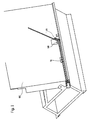
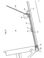
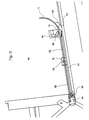
- a hollow profile bar 53 on a conveyor track 54 arranged at the lower end of a support wall 60 is up to a stop 57 in the area of a bending point 58/59 transported
- the stop 57 can also in front of the bending point in the conveyor track his.
- the stop 57 can with a Switch to be equipped of the feed conveyor (not shown) stops and the detection of the hollow profile bar 53 triggers by the gripper 51. So will the hollow profile bar 53 from the gripper 51 in a precisely defined Location recorded.
- the transported beyond the bending point 58/59 Section 53 'of the hollow profile bar 53 is on the Support wall 60 adjacent to the bending lever 59 Abutment 58 bent around.
- the bending point owns preferably that described below with reference to FIGS. 3 to 8 Construction.
- the device can, for example have the structure known from DE-GM 87 05 796 and a support finger (indicated in Fig. 9) have, as he also in the known device is provided.
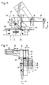
- the device shown in FIGS. 3 to 8 for Bending hollow profile strips 53 consists of a Clamp 2 with a stationary jaw 3 and one opposite to it movable jaw 4 (in 3, the jaw 4 is not shown).
- the moveable Clamping jaw 4 is over guide pins 5 and 6, which are arranged in pairs in the direction of the double arrow 7 displaceable, so that the mouth width the clamp 2 to the width of the hollow profile bar to be bent 53 can be adjusted.
- the bending device also has a hold-down device 20, which serves as an abutment during bending.
- the hold-down device 20 is exchangeable in a carrier 21 used.
- a groove 23 is in the carrier 21 recessed into which the hold-down 20 with sliding fit can be used and for example by a screw 24 is held.
- the carrier 21 for the hold-down device 20 is on one Lever 25 mounted around a machine frame fixed Warehouse 26, i.e. a camp opposite the stationary jaw 3 of terminal 2 is not movable with the help of a linear motor 27, e.g. one double-acting pressure medium cylinder, in the direction of the double arrow 28 from the continuous in Fig. 3 Lines shown operative position in the in Fig. 3rd Stand-by position shown in dash-dot lines is pivotable.
- a linear motor 27 e.g. one double-acting pressure medium cylinder
- the carrier 21 for the hold-down device 20 perpendicular to the plane of symmetry the terminal 2, namely in the direction of the in Fig. 4th drawn double arrow 29 adjustable.
- a linear motor in the exemplary embodiment shown] a double-acting pressure medium cylinder 32 is provided, whose piston rod 33 via a tie rod 34 is coupled to the carrier 21.
- the hold-down device 20 cannot only in a parallel to the plane of symmetry of terminal 2 Level pivoted (double arrow 28), but also in one to the plane of symmetry of terminal 2 vertical direction (double arrow 29) can be adjusted, so that the hold-down 20 entirely from the Bending area can be moved out.
- the hold-down 20 carries on its front End, that of two inclined surfaces 36, which extend longitudinally of the hold-down device 20 has an acute angle include, is formed, a bead-like Approach 35, which shows as Fig. 6, the upper surface of the Hollow profile 53, which is in the terminal 2 between the Jaws 3 and 4 is clamped before Start of the bending process when swiveling the Hold-down 20 bulges somewhat into its operative position.
- the bending device according to the invention provided that the front end of the Hold-down device 20 and there to the inclined surfaces 36 subsequent, bead-shaped approach 35 something narrower than the clear distance between the facing surfaces of the jaws 3 and 4 of clamp 2. So the side walls 40 of the hollow profile bar 53 to be bent during the bending process is also supported from the inside, as indicated in the section of FIG. 7.
- the bending device according to the invention also has a bending lever 59 with a bending attachment 62, which is pivotable about an axis that with the axis 37 of the bead 35 at the front end of the Hold-down device 20 collapses when it is in its active position is (the surfaces 41 lie on the surfaces 42 of the jaw 3).
- the swivel area of the bending lever 59 is not shown in FIG. 3 90 ° limited, but also goes above out so that after swinging out (arrow 28) and laterally shifting (arrow 29) the hold-down device 20 also acute angles between the two the corner 61 generated in the hollow profile bar 53 adjacent Leg of the hollow profile bar 53 bent can be.
- Terminal 2 opened and the hollow profile bar 53 on the upper guide pins 6 or on the conveyor track 54 transported to the pins 6.
- the inner surfaces of the Jaws 3 and 4 are then on the side surfaces 40 on, the hold-down 20 in its in the 3 and 6 the active position shown moves and bulges the upward-facing wall of the hollow profile strip 53 something down.
- the hollow profile bar 53 is located thus remains in a "zero" position at the same time the gripper 52 mounted on the slide 51 the hollow profile bar 53 firmly in place.
- the stop 57 will now sunk into the conveyor track 54 and the carriage 51 with moves the profile 53 clamped by the gripper 52 now in the direction of the bending lever 59 the distance that a process computer specifies and which corresponds to the length of the frame leg.
- the effectively driven length is from an incremental encoder 56 determined. If the sled 51 reaches the Endpoint of its predetermined and effectively measured Movement, the bending lever 59 bends the protruding Section 53 'along the backwards inclined support wall 60 around that of a process computer predetermined angle upwards.
- the exact measurement of those driven by the slide 51 Distance is determined by an incremental encoder 56, and the movement of the carriage 51 is over this controlled.
- the incremental encoder 56 is on the drive motor 55 or on the movement 54 of the slide 51 assembled.
- the carriage 51 is used, for example, by a Endless toothed belt driven, and is on one guided parallel to the conveyor track 54.
- the engagement of the toothed belt in the drive gear of the drive motor 55 is exact and free of play, so that also directly on the engine-gearbox unit mounted incremental encoder 56 the driven Register the exact distance of the slide 51 can.
- the effective route of the sledge 51 corresponds to the profile length which the process computer intended for a bending process.
- the hollow profile bar 53 turns and this is held by the jaws 3 and 4 , the gripper mounted on the slide 51 is released 52.
- the carriage 51 then travels at high speed to the starting position (reference point) back.
- the gripper 52 grips the hollow profile strip 53 again and the carriage 51 moves after the bending process again exactly the one from the process computer given route before, he the hollow profile bar 53 advances without slip.
- the conveyor track 54 be a simple slideway.
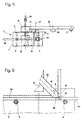
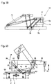
- a hollow profile bar 53 is conveyed by a conveyor, which, for example, the slide 51 with the Gripper 52 can be, for example, starting from the reference position determined by the fitting 57 is so far advanced that the over the Downholder 20 protruding section 53 'of the hollow profile bar 53 who decreased by a certain distance "x" Length of the first leg to be manufactured Spacer frame corresponds.
- This Position is shown in Fig. 9b.
- the lie down Bake 3 and 4 on the hollow profile bar 53 and the Carriage 51 returns to its original position, which in 9a is shown. After this return movement of the carriage 51 is finished, or still during the same, the section 53 'around the hold-down device 20 in the direction of the arrow in Fig. 9b Bending lever 59 bent upwards.
- the hollow profile bar 53rd released from jaws 3 and 4 and the sled 51 moves with from both sides or from above and below to the hollow profile bar 53 Gripper 52 in the position shown in Fig. 9c before, pushing the hollow profile bar 53 so far, that the next (second) position in which in the Hollow profile bar 53 is a corner 61 to create opposite the hold-down device 20 is aligned.
- Now jaws 3 and 4 close again and hold the hollow profile bar 53 immovably and the The next (second) bending process is done with the help of the bending lever 59 executed while the slide 51 returns to its original position.
- the slide 51 with the hollow profile bar 53 applied Gripper 52 by a distance that is the length of the next leg of the spacer frame to be manufactured corresponds so that the next (Third) bending point opposite the hold-down device 20 is aligned.
- the jaws close 3.4 again and hold the hollow profile bar 53, whereupon the third bending process is carried out.
- the fourth bending process is carried out the front end 172 of the supplied hollow profile strip 53 and / or section 173 of the partial finished spacer frame from the Bending plane can be deflected or just the front End 172 is moved down so that the fourth bending process is not hindered.
- At least one corner 61 and with at least one curved section 71 are to be produced (see FIG. 22), can also be used with a hold-down without freely rotatable roller 70, i.e. with a hold-down 20, as shown in Figs. 3 to 8, the at its front end an approach similar or identical to the approach 35, or the like 19 to 21 described below with reference to FIGS. is trained.
- the bending lever 59 is curved when generating Sections 71 in hollow profile strips 53 opposite the conveying direction of the hollow profile bar 53 according to the desired radius of curvature so slanted so that between the cheeks 3 and 4 emerging hollow profile bar 53 from the bending approach 62 deflected upwards on the bending lever 59 and is continuously curved.
- the width of the roller 70 is, as in particular Fig. Figure 16 shows slightly narrower than the width of the one to be curved Hollow profile bar 53 so that the inner wall the hollow profile bar 53, as can also be seen in FIG. 16, during the curving process inwards is deformed. This will compress the inner wall the hollow profile bar 53 is reduced, so that a largely smooth inner wall in the curved Section 71 of the hollow profile bar 53 results.
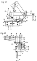
- FIG. 18 A particularly favorable embodiment of a Gripper 51, the necessary friction for the exact feed of the hollow profile strip to be curved 53 is shown in Fig. 18. It can be seen that the lower jaw 75 with a in the conveying direction guided on at least one guide rail Carriage 76 is rigidly connected, whereas the upper Cheek 77 over parallelogram 78 through one Pressure motor 79 with respect to the jaw 75 is pivotable away. The movable jaw 77 can therefore pivoted behind the support wall 60 of the device be so that they are the removal of a Completely bent spacer frame is not hindered.
- the stop can 57 based on the conveying direction of the hollow profile bar 53 in front of the tool with the hold-down device 20 or 80 and the bending lever 59 are arranged his.
- the stop 57 with a limit switch is preferred equipped and is based on the conveying direction of the hollow profile bar 53, according to the End of the gripper stroke away from the tool 51.
- a hollow profile strip 53 promoted in the device up to the fitting 57 become, whereupon its switch is operated and controlled by a sequential circuit, the gripper 51 the hollow profile bar 53 in a precisely defined Location takes over.
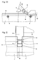
- the device shown in Figs. 19 to 21 corresponds essentially to that with reference to FIGS. 10 to 17 described device, however, is in the hold-down device 80 instead of the freely rotatable roller 70 a slider 81 inserted through which the inner wall of the Hollow profile bar 53, as shown in Fig. 21, during of the curvature is deformed inwards.
- devices can has been, such as that described with reference to FIGS. 1 to 8 Device to be executed and also how shown in Fig. 9 can be used.
- Both the hold-down 80 with the roller 70, as the hold-down 20 with its neck 35 are also in the conveying direction, i.e. parallel to one of the guide pins 6 connecting level adjustable. So that can the position of the hold-down the geometric conditions be adjusted after changing the angular position of the lever 50 with the ramp surface 62 result.
- a hold-down 20 with extension 35 or a hold-down 80 bending tool equipped with approach 81 can Hollow profile strips 53 also for spacer frames for Insulating glass panes are bent, at least a sharp angled corner 61 and at least one for example after a partial arc have curved portion 71.
- An example for such a frame is shown in Fig. 22.
- the advantage here is that with the invention Device, if the hold-down 20 with the neck 35 or the hold-down device 80 with the attachment 81 is used, even without changing tools sharp corners when creating these corners the feed for the hollow profile bar 53 when moving up of the bending lever 59 shut down - as well (Arc-shaped) curved sections - thereby the feed for the hollow profile bar 53 is more or bending lever 59 pivoted up little actuated with the ramp surface 62 - are produced can.
Landscapes
- Engineering & Computer Science (AREA)
- Mechanical Engineering (AREA)
- Civil Engineering (AREA)
- Structural Engineering (AREA)
- Bending Of Plates, Rods, And Pipes (AREA)
- Blow-Moulding Or Thermoforming Of Plastics Or The Like (AREA)
- Shaping Of Tube Ends By Bending Or Straightening (AREA)
- Container Filling Or Packaging Operations (AREA)
- Food-Manufacturing Devices (AREA)
- Laminated Bodies (AREA)
Claims (20)
- Procédé pour réaliser des sections (71) à courbure continue dans des barres de profilés creux (53), dans lequel la barre de profilé creux (53), supportée par le dessous, est transportée sous un dispositif presseur (20, 80) entre desjoues de guidage (3, 4) et, à la sortie du dispositif presseur (20, 80), est déviée par rapport à la direction de transport de la barre de profilé creux (53) par une surface d'appui (62) d'un levier de pliage (59) inclinée par rapport à la direction de transport de la barre, caractérisé par le fait que la surface d'appui (62) reste fixe en position active pendant le processus de cintrage, par le fait que la paroi de la barre de profilé creux (53), côté extérieur de la courbe, glisse le long de la surface d'appui (62) inclinée pendant toute la durée du processus de cintrage et par le fait qu'au cours du cintrage de la barre de profilé creux (53), la paroi de la barre de profilé creux (53), côté intérieur de la courbe, est déformée en direction de la paroi de la barre de profilé creux (53), côté extérieur de la courbe, par le dispositif presseur (20, 80).
- Procédé selon la revendication 1, caractérisé par le fait que l'on règle le rayon de la courbure par la valeur de la déviation de la barre de profilé creux (53).
- Procédé selon la revendication 1 ou 2, caractérisé par le fait que l'on règle la longueur de la section (71) cintrée de la barre de profilé creux (53) par la valeur de l'avance avec déviation de la barre de profilé creux (53) après le dispositif presseur (20, 80).
- Procédé de fabrication d'intercalaires pour des vitrages isolants qui comportent au moins une section courbe (71) et au moins un angle vif (61), caractérisé par le fait que, lors de la réalisation de la section en arc de cercle (71), on fait avancer la barre de profilé creux (53) sous le dispositif presseur (20, 80), entre des joues de guidage (3, 4) et, à la sortie du dispositif presseur (20, 80) on dévie la barre de profilé creux (53) par rapport à sa direction de transport conformément au procédé selon l'une des revendications 1 à 3 et par le fait que pour réaliser un angle vif (61) dans la barre de profilé creux (53), on plie la partie de celle-ci (53) qui dépasse au-delà du dispositif presseur (20, 80) en faisant pivoter de l'angle souhaité le levier de pliage (59), sa surface d'appui (62) étant appliquée contre la partie dépassante de la barre de profilé (53), tandis que la barre de profilé creux est arrêtée.
- Dispositif pour réaliser des sections (71) à courbure continue dans des barres de profilés creux (53), en particulier lors de la fabrication d'intercalaires pour vitrages isolants, comportant un chemin de transport (54) sensiblement horizontal, un dispositif d'avance (51, 52) associé au chemin de transport (54) pour amener la barre de profilé creux à un outil, lequel dispositif présente deux joues de guidage (3, 4) entre lesquelles la barre de profilé est placée, un dispositif presseur (20, 80) pour la barre de profilé creux (53), dont l'extrémité antérieure (53, 70, 81), en position active, est appliquée contre la paroi intérieure tournée vers lui de la barre de profilé (53) et un levier (59) qui peut pivoter vers le haut par rapport à la direction de transport et présente une surface d'appui (62) pour la barre de profilé creux (53), caracterisé par le fait que le chemin de transport (54) se trouve à l'extrémité inférieure d'une surface d'appui (69) (latérale) pour la section courbe (71) au nombre d'au moins une de la barre de profilé creux (53), par le fait que les joues de guidage (3, 4) sont disposées de chaque côté de la barre de profilé creux (53), par le fait que le dispositif presseur (20, 80) est mobile et, en position active, s'engage par son extrémité antérieure (35, 70, 81) entre les joues de guidage (3, 4) de telle sorte que l'extrémité antérieure (35, 70, 81) du dispositif presseur (20, 80) soit appliquée contre la paroi intérieure de la barre de profilé creux par le fait que le dispositif presseur (20, 80) présente un jeu latéral par rapport aux joues de guidage (3, 4) et peut être appliqué contre la paroi intérieure de la barre de profilé creux (53) de manière telle que, pendant le processus de cintrage, ladite. paroi intérieure soit déformée en direction de la paroi extérieure de la barre de profilé creux (53) et par le fait que le levier de pliage (59) avec sa surface d'appui (62) pour la partie de barre de profilé creux (53) sortant des joues de guidage (3, 4) peut être immobilisée dans une position angulaire quelconque par rapport à la direction de transport de la barre de profilé creux (53).
- Dispositif selon la revendication 5, caractérisé par le fait que le dispositif d'avance est une pince (52) qui peut être appliquée sur la barre de profilé creux (53) et est montée sur un chariot (51) avec possibilité de déplacement suivant un mouvement de va-et-vient parallèlement à la direction de transport de la barre de profilé creux (53), la pince agissant sur la barre de profilé creux (53) durant sa couse en direction de l'outil.
- Dispositif selon la revendication 6, caractérisé par le fait que la pince (52) comporte des mâchoires (77, 75) qui peuvent être appliquées par le dessus et par le dessous sur la barre de profilé creux (53).
- Dispositif selon la revendication 7, caractérisé par le fait que la mâchoire inférieure (75) de la pince (52) est montée fixe sur le chariot (51) tandis que la mâchoire supérieure (77) de la pince (52) est montée mobile sur le chariot (51).
- Dispositif selon la revendication 8, caractérisé par le fait que la mâchoire (75) mobile est montée sur un support (76) au moyen d'un mécanisme à parallélogramme (78).
- Dispositif selon l'une des revendications 5 à 9, caractérisé par le fait que le dispositif presseur (20, 80) est fixé sur un support (21) qui peut être réglé aussi bien dans ou parallèlement au plan de symétrie des joues de guidage (3, 4) que perpendiculairement audit plan de symétrie aux fins d'éloigner le dispositif presseur (20, 80) du plan de pliage.
- Dispositif selon la revendication 10, caractérisé par le fait que le support (21) pour le dispositif presseur (20, 80) peut pivoter autour d'un axe (26) perpendiculaire au plan de symétrie des joues de guidage (3, 4).
- Dispositif selon la revendication 10 ou 11, caractérisé par le fait que le support (21) pour le dispositif presseur (20, 80) est guidé dans un guide-support (31) avec possibilité de déplacement perpendiculairement au plan de symétrie des joues de guidage (3, 4).
- Dispositif selon l'une des revendications 10 à 12, caractérisé par le fait que le support (21) pour le dispositif presseur (20, 80) est monté sur un levier (25) qui est monté dans le dispositif avec possibilité de pivotement autour d'un axe (26) perpendiculaire au plan de symétrie des joues de guidage (3,).
- Dispositif selon l'une des revendications 10 à 13, caractérisé par le fait que le dispositif presseur (20, 80) est fixé sur son support (21) de manière interchangeable.
- Dispositif selon l'une des revendications 5 à 14, caractérisé par le fait le dispositif presseur (20) porte à son extrémité antérieure un patin (35, 81).
- Dispositif selon l'une des revendications 5 à 14, caractérisé par le fait que le dispositif presseur (80) porte à son extrémité antérieure un galet (70) qui peut tourner librement.
- Dispositif selon l'une des revendications 10 à 16, caractérisé par le fait qu'il est monté sur le support (21), en tant que dispositif presseur pouvant être utilisé de manière sélective, un dispositif presseur (20) qui à son extrémité antérieure porte un patin (35, 81) appliqué contre la barre de profilé creux (53) et un dispositif presseur (80) qui à son extrémité antérieure porte un galet (70) tournant librement, lesquels dispositifs presseurs peuvent être amenés alternativement et de manière sélective dans leur position active entre les joues de guidage (3, 4).
- Dispositif selon l'une des revendications 15 à 17, caractérisé par le fait que le patin (35, 81) ou le galet (70) est plus étroit que la barre de profilé creux (53).
- Dispositif selon l'une des revendications 15, 17 ou 18 caractérisé par le fait que le patin (35, 81) est courbé ou bombé au moins autour d'un axe perpendiculaire à la direction de transport ou au plan de pliage.
- Dispositif selon l'une des revendications 15 à 19 caractérisé par le fait que le patin (81) ou le galet (70) est fixé avex possibilité de remplacement sur le dispositif presseur (20, 80).
Applications Claiming Priority (9)
| Application Number | Priority Date | Filing Date | Title |
|---|---|---|---|
| AT112690 | 1990-05-21 | ||
| AT1126/90 | 1990-05-21 | ||
| AT112690A AT397054B (de) | 1990-05-21 | 1990-05-21 | Vorrichtung zum biegen von hohlprofilleisten |
| AT1840/90 | 1990-09-10 | ||
| AT184090A AT397775B (de) | 1990-09-10 | 1990-09-10 | Verfahren und vorrichtung zum krümmen von hohlprofilleisten |
| AT184090 | 1990-09-10 | ||
| AT1987/90 | 1990-10-02 | ||
| AT198790A AT405912B (de) | 1990-10-02 | 1990-10-02 | Verfahren und vorrichtung zum krümmen von hohlprofilleisten |
| AT198790 | 1990-10-02 |
Publications (3)
| Publication Number | Publication Date |
|---|---|
| EP0459971A1 EP0459971A1 (fr) | 1991-12-04 |
| EP0459971B1 EP0459971B1 (fr) | 1994-03-09 |
| EP0459971B2 true EP0459971B2 (fr) | 2001-12-12 |
Family
ID=27147132
Family Applications (1)
| Application Number | Title | Priority Date | Filing Date |
|---|---|---|---|
| EP91890106A Expired - Lifetime EP0459971B2 (fr) | 1990-05-21 | 1991-05-15 | Procédé et dispositif pour obtenir des parties pliées dans les profilés d'écartement creux |
Country Status (7)
| Country | Link |
|---|---|
| EP (1) | EP0459971B2 (fr) |
| JP (1) | JPH0768322A (fr) |
| AT (1) | ATE102513T1 (fr) |
| DE (2) | DE59101137D1 (fr) |
| DK (1) | DK0459971T3 (fr) |
| ES (1) | ES2051110T5 (fr) |
| NO (1) | NO179493C (fr) |
Families Citing this family (8)
| Publication number | Priority date | Publication date | Assignee | Title |
|---|---|---|---|---|
| DK282090A (da) * | 1990-11-28 | 1992-05-29 | Skovgaard & Co As | Fremgangsmaade samt apparat til fremstilling af lukkede afstandsrammer af hule tyndvaeggede profiler |
| DE4214205A1 (de) * | 1992-04-30 | 1993-11-04 | Happich Gmbh Gebr | Vorrichtung zum biegen von profilleistenabschnitten o. dgl. |
| DE59304791D1 (de) * | 1992-07-16 | 1997-01-30 | Peter Lisec | Vorrichtung zum Herstellen von Abstandhalterrahmen für Isolierglasscheiben aus Hohlprofilleisten |
| AT406236B (de) † | 1995-10-31 | 2000-03-27 | Lisec Peter | Vorrichtung zum biegen oder krümmen von hohlprofilleisten |
| DE10137766A1 (de) * | 2001-08-03 | 2003-02-27 | Lenhardt Maschinenbau | Vorrichtung zum Biegen von Hohlprofilstäben |
| DE10236407B4 (de) * | 2002-08-02 | 2007-09-27 | Lenhardt Maschinenbau Gmbh | Vorrichtung zum Biegen von Hohlprofilstäben |
| CA2924182C (fr) * | 2015-04-02 | 2022-12-06 | Lombarda Macchine S.A.S. Di G.B. Lattuada & C. | Methode de courbure automatique d'elements espaceurs en vue d'isoler les panneaux de verre a double vitrage et machine servant a mener la methode |
| CN111531858A (zh) * | 2020-05-12 | 2020-08-14 | 周立 | 一种汽车玻璃卡条弯曲装置 |
Citations (1)
| Publication number | Priority date | Publication date | Assignee | Title |
|---|---|---|---|---|
| DE3807529A1 (de) † | 1988-03-08 | 1989-09-21 | Bayer Isolierglasfab Kg | Verfahren und vorrichtung zum biegen von hohlen abstandhalterprofilen |
Family Cites Families (8)
| Publication number | Priority date | Publication date | Assignee | Title |
|---|---|---|---|---|
| US3885412A (en) * | 1973-11-21 | 1975-05-27 | Lawrence T Vance | Method of fabricating curved tubing and product thereof |
| AT360311B (de) * | 1978-09-26 | 1980-01-12 | Seraphin Puempel & Soehne Kg | Biegeeinrichtung zum anfertigen eines distanz- halterahmens fuer isolierglasscheiben |
| CH647428A5 (en) * | 1980-08-15 | 1985-01-31 | Haeusler Ag Chr | Process for bending a sectional bar, apparatus for supporting portions of a sectional bar relative to one another and multi-roll bending machine |
| CH660398A5 (de) * | 1982-01-21 | 1987-04-15 | Peter Lisec | Abstandhalterrahmen fuer isolierglasscheiben sowie verfahren zur herstellung desselben und vorrichtung zur durchfuehrung des verfahrens. |
| DE3312764A1 (de) * | 1983-04-09 | 1984-10-18 | Fr. Xaver Bayer Isolierglasfabrik Kg, 7807 Elzach | Verfahren und vorrichtung zum biegen von abstandhalter-profilen fuer isolierglasscheiben |
| AT389662B (de) * | 1985-02-25 | 1990-01-10 | Lisec Peter Glastech Ind | Vorrichtung zum stumpfschweissen |
| AT401627B (de) * | 1987-03-09 | 1996-10-25 | Lisec Peter | Vorrichtung zum herstellen von abstandhalterrahmen für isolierglasscheiben |
| DE3740921A1 (de) * | 1987-12-03 | 1989-06-15 | Bayer Isolierglasfab Kg | Vorrichtung zur herstellung einer biegung an einem hohlen rechteck-profil |
-
1991
- 1991-05-15 ES ES91890106T patent/ES2051110T5/es not_active Expired - Lifetime
- 1991-05-15 EP EP91890106A patent/EP0459971B2/fr not_active Expired - Lifetime
- 1991-05-15 DK DK91890106.7T patent/DK0459971T3/da not_active Application Discontinuation
- 1991-05-15 DE DE91890106T patent/DE59101137D1/de not_active Expired - Fee Related
- 1991-05-15 AT AT91890106T patent/ATE102513T1/de not_active IP Right Cessation
- 1991-05-16 NO NO911925A patent/NO179493C/no not_active Application Discontinuation
- 1991-05-21 DE DE4116521A patent/DE4116521C2/de not_active Expired - Fee Related
- 1991-05-21 JP JP3145531A patent/JPH0768322A/ja active Pending
Patent Citations (1)
| Publication number | Priority date | Publication date | Assignee | Title |
|---|---|---|---|---|
| DE3807529A1 (de) † | 1988-03-08 | 1989-09-21 | Bayer Isolierglasfab Kg | Verfahren und vorrichtung zum biegen von hohlen abstandhalterprofilen |
Also Published As
| Publication number | Publication date |
|---|---|
| ES2051110T3 (es) | 1994-06-01 |
| JPH0768322A (ja) | 1995-03-14 |
| DE4116521A1 (de) | 1991-11-28 |
| EP0459971B1 (fr) | 1994-03-09 |
| EP0459971A1 (fr) | 1991-12-04 |
| DK0459971T3 (da) | 1994-04-05 |
| DE4116521C2 (de) | 1998-07-23 |
| DE59101137D1 (de) | 1994-04-14 |
| NO911925D0 (no) | 1991-05-16 |
| ES2051110T5 (es) | 2002-07-16 |
| NO911925L (no) | 1991-11-22 |
| ATE102513T1 (de) | 1994-03-15 |
| NO179493B (no) | 1996-07-08 |
| NO179493C (no) | 1996-10-16 |
Similar Documents
| Publication | Publication Date | Title |
|---|---|---|
| DE3223881C2 (de) | Abstandhalterrahmen sowie Verfahren und Vorrichtung zum Biegen von Hohlprofilleisten zu Abstandhalterrahmen für Isolierglas | |
| AT403350B (de) | Biegemaschine zum herstellen eines abstandhaltenden innenrahmens für eine isolierglasscheibe | |
| EP0461100B2 (fr) | Procédé et dispositif pour plier des profilés d'écartement creux pour double vitrage | |
| EP0459971B2 (fr) | Procédé et dispositif pour obtenir des parties pliées dans les profilés d'écartement creux | |
| DE4116268C2 (fr) | ||
| EP0579593B1 (fr) | Dispositif pour la fabrication de cadres d'espacement pour vitres isolantes à partir de profilés d'écartement creux | |
| EP0449801B1 (fr) | Dispositif pour plier des profilés d'écartement creux pour double vitrage | |
| AT406889B (de) | Verfahren und vorrichtung zum herstellen von abstandhalterrahmen für isolierglasscheiben aus hohlprofilleisten | |
| EP0249946A2 (fr) | Procédé et dispositif pour la fabrication d'un cadre d'espacement pour vitres isolantes | |
| EP0771597B2 (fr) | Dispositif pour plier ou courber des profilés creux | |
| AT397775B (de) | Verfahren und vorrichtung zum krümmen von hohlprofilleisten | |
| AT397055B (de) | Verfahren und vorrichtung zum biegen von hohlprofilleisten zu abstandhalterrahmen für isolierglasscheiben | |
| DE9016129U1 (de) | Vorrichtung zum Krümmen von Profilleisten | |
| AT405912B (de) | Verfahren und vorrichtung zum krümmen von hohlprofilleisten | |
| EP0042450B1 (fr) | Procédé pour la fabrication d'enveloppes de pots d'échappement à joint longitudinal plié et dispositif pour la réalisation de ce procédé | |
| AT397054B (de) | Vorrichtung zum biegen von hohlprofilleisten | |
| EP1285708B1 (fr) | Méthode et dispositif pour le cintrage des profilés d'écartement pour les vitrages isolants | |
| DE102004060805A1 (de) | Verfahren und Vorrichtung zum Biegen von Hohlprofilstäben, insbesondere für Abstandhalterrahmen von Isolierglasscheiben | |
| DE4117002A1 (de) | Verfahren und vorrichtung zum biegen von hohlprofilleisten zu abstandhalterrahmen fuer isolierglasscheiben | |
| DE2203913A1 (de) | Verfahren und vorrichtung zum ankuppen von drahtpinnen | |
| DE3627152A1 (de) | Verfahren und vorrichtung zum herstellen eines abstandhalterrahmens fuer isolierglas | |
| DE8909188U1 (de) | Profilwalzmaschine | |
| AT410909B (de) | Verfahren und vorrichtung zum biegen von hohlprofilleisten zu abstandhalterrahmen für isolierglasscheiben | |
| EP4556671A1 (fr) | Vitrage isolant à croisillons, et dispositif et procédé d'assemblage d'un tel vitrage | |
| AT401242B (de) | Vorrichtung zum herstellen von abstandhalterrahmen für isolierglasscheiben aus hohlprofilleisten |
Legal Events
| Date | Code | Title | Description |
|---|---|---|---|
| PUAI | Public reference made under article 153(3) epc to a published international application that has entered the european phase |
Free format text: ORIGINAL CODE: 0009012 |
|
| AK | Designated contracting states |
Kind code of ref document: A1 Designated state(s): AT CH DE DK ES FR GB IT LI SE |
|
| 17P | Request for examination filed |
Effective date: 19911021 |
|
| 17Q | First examination report despatched |
Effective date: 19930430 |
|
| GRAA | (expected) grant |
Free format text: ORIGINAL CODE: 0009210 |
|
| AK | Designated contracting states |
Kind code of ref document: B1 Designated state(s): AT CH DE DK ES FR GB IT LI SE |
|
| REF | Corresponds to: |
Ref document number: 102513 Country of ref document: AT Date of ref document: 19940315 Kind code of ref document: T |
|
| ET | Fr: translation filed | ||
| REG | Reference to a national code |
Ref country code: DK Ref legal event code: T3 |
|
| GBT | Gb: translation of ep patent filed (gb section 77(6)(a)/1977) |
Effective date: 19940303 |
|
| REF | Corresponds to: |
Ref document number: 59101137 Country of ref document: DE Date of ref document: 19940414 |
|
| REG | Reference to a national code |
Ref country code: ES Ref legal event code: FG2A Ref document number: 2051110 Country of ref document: ES Kind code of ref document: T3 |
|
| ITF | It: translation for a ep patent filed | ||
| PLBI | Opposition filed |
Free format text: ORIGINAL CODE: 0009260 |
|
| EAL | Se: european patent in force in sweden |
Ref document number: 91890106.7 |
|
| 26 | Opposition filed |
Opponent name: LENHARDT MASCHINENBAU GMBH Effective date: 19941209 |
|
| PLAW | Interlocutory decision in opposition |
Free format text: ORIGINAL CODE: EPIDOS IDOP |
|
| APAE | Appeal reference modified |
Free format text: ORIGINAL CODE: EPIDOS REFNO |
|
| APAC | Appeal dossier modified |
Free format text: ORIGINAL CODE: EPIDOS NOAPO |
|
| APAC | Appeal dossier modified |
Free format text: ORIGINAL CODE: EPIDOS NOAPO |
|
| APAC | Appeal dossier modified |
Free format text: ORIGINAL CODE: EPIDOS NOAPO |
|
| PLAW | Interlocutory decision in opposition |
Free format text: ORIGINAL CODE: EPIDOS IDOP |
|
| APAC | Appeal dossier modified |
Free format text: ORIGINAL CODE: EPIDOS NOAPO |
|
| APAE | Appeal reference modified |
Free format text: ORIGINAL CODE: EPIDOS REFNO |
|
| APAC | Appeal dossier modified |
Free format text: ORIGINAL CODE: EPIDOS NOAPO |
|
| PGFP | Annual fee paid to national office [announced via postgrant information from national office to epo] |
Ref country code: DK Payment date: 20010531 Year of fee payment: 11 |
|
| APAC | Appeal dossier modified |
Free format text: ORIGINAL CODE: EPIDOS NOAPO |
|
| PLAW | Interlocutory decision in opposition |
Free format text: ORIGINAL CODE: EPIDOS IDOP |
|
| PUAH | Patent maintained in amended form |
Free format text: ORIGINAL CODE: 0009272 |
|
| STAA | Information on the status of an ep patent application or granted ep patent |
Free format text: STATUS: PATENT MAINTAINED AS AMENDED |
|
| 27A | Patent maintained in amended form |
Effective date: 20011212 |
|
| AK | Designated contracting states |
Kind code of ref document: B2 Designated state(s): AT CH DE DK ES FR GB IT LI SE |
|
| REG | Reference to a national code |
Ref country code: CH Ref legal event code: AEN Free format text: AUFRECHTERHALTUNG DES PATENTES IN GEAENDERTER FORM |
|
| REG | Reference to a national code |
Ref country code: GB Ref legal event code: IF02 |
|
| PG25 | Lapsed in a contracting state [announced via postgrant information from national office to epo] |
Ref country code: DK Free format text: LAPSE BECAUSE OF FAILURE TO SUBMIT A TRANSLATION OF THE DESCRIPTION OR TO PAY THE FEE WITHIN THE PRESCRIBED TIME-LIMIT Effective date: 20020312 |
|
| GBTA | Gb: translation of amended ep patent filed (gb section 77(6)(b)/1977) | ||
| ET3 | Fr: translation filed ** decision concerning opposition | ||
| REG | Reference to a national code |
Ref country code: ES Ref legal event code: DC2A Kind code of ref document: T5 Effective date: 20020312 |
|
| PGFP | Annual fee paid to national office [announced via postgrant information from national office to epo] |
Ref country code: SE Payment date: 20050516 Year of fee payment: 15 |
|
| APAH | Appeal reference modified |
Free format text: ORIGINAL CODE: EPIDOSCREFNO |
|
| PGFP | Annual fee paid to national office [announced via postgrant information from national office to epo] |
Ref country code: CH Payment date: 20060515 Year of fee payment: 16 |
|
| PG25 | Lapsed in a contracting state [announced via postgrant information from national office to epo] |
Ref country code: SE Free format text: LAPSE BECAUSE OF NON-PAYMENT OF DUE FEES Effective date: 20060516 |
|
| PGFP | Annual fee paid to national office [announced via postgrant information from national office to epo] |
Ref country code: FR Payment date: 20060519 Year of fee payment: 16 Ref country code: DE Payment date: 20060519 Year of fee payment: 16 |
|
| PGFP | Annual fee paid to national office [announced via postgrant information from national office to epo] |
Ref country code: GB Payment date: 20060522 Year of fee payment: 16 |
|
| PGFP | Annual fee paid to national office [announced via postgrant information from national office to epo] |
Ref country code: ES Payment date: 20060530 Year of fee payment: 16 |
|
| EUG | Se: european patent has lapsed | ||
| REG | Reference to a national code |
Ref country code: CH Ref legal event code: PL |
|
| GBPC | Gb: european patent ceased through non-payment of renewal fee |
Effective date: 20070515 |
|
| PG25 | Lapsed in a contracting state [announced via postgrant information from national office to epo] |
Ref country code: LI Free format text: LAPSE BECAUSE OF NON-PAYMENT OF DUE FEES Effective date: 20070531 Ref country code: CH Free format text: LAPSE BECAUSE OF NON-PAYMENT OF DUE FEES Effective date: 20070531 |
|
| REG | Reference to a national code |
Ref country code: FR Ref legal event code: ST Effective date: 20080131 |
|
| PG25 | Lapsed in a contracting state [announced via postgrant information from national office to epo] |
Ref country code: DE Free format text: LAPSE BECAUSE OF NON-PAYMENT OF DUE FEES Effective date: 20071201 |
|
| PG25 | Lapsed in a contracting state [announced via postgrant information from national office to epo] |
Ref country code: GB Free format text: LAPSE BECAUSE OF NON-PAYMENT OF DUE FEES Effective date: 20070515 |
|
| PG25 | Lapsed in a contracting state [announced via postgrant information from national office to epo] |
Ref country code: FR Free format text: LAPSE BECAUSE OF NON-PAYMENT OF DUE FEES Effective date: 20070531 |
|
| REG | Reference to a national code |
Ref country code: ES Ref legal event code: FD2A Effective date: 20070516 |
|
| PG25 | Lapsed in a contracting state [announced via postgrant information from national office to epo] |
Ref country code: ES Free format text: LAPSE BECAUSE OF NON-PAYMENT OF DUE FEES Effective date: 20070516 |
|
| PGFP | Annual fee paid to national office [announced via postgrant information from national office to epo] |
Ref country code: IT Payment date: 20100520 Year of fee payment: 20 Ref country code: AT Payment date: 20100520 Year of fee payment: 20 |