EP0460068B1 - Post-mix-getränkespender mit warmwasserablauf - Google Patents
Post-mix-getränkespender mit warmwasserablauf Download PDFInfo
- Publication number
- EP0460068B1 EP0460068B1 EP90904122A EP90904122A EP0460068B1 EP 0460068 B1 EP0460068 B1 EP 0460068B1 EP 90904122 A EP90904122 A EP 90904122A EP 90904122 A EP90904122 A EP 90904122A EP 0460068 B1 EP0460068 B1 EP 0460068B1
- Authority
- EP
- European Patent Office
- Prior art keywords
- water
- valve
- dispenser
- automatic
- beverage dispensing
- Prior art date
- Legal status (The legal status is an assumption and is not a legal conclusion. Google has not performed a legal analysis and makes no representation as to the accuracy of the status listed.)
- Expired - Lifetime
Links
- XLYOFNOQVPJJNP-UHFFFAOYSA-N water Substances O XLYOFNOQVPJJNP-UHFFFAOYSA-N 0.000 title claims abstract description 51
- 235000013361 beverage Nutrition 0.000 title claims abstract description 36
- 238000010926 purge Methods 0.000 title claims abstract description 24
- 238000001816 cooling Methods 0.000 claims abstract description 9
- 239000006188 syrup Substances 0.000 claims description 17
- 235000020357 syrup Nutrition 0.000 claims description 17
- 238000000034 method Methods 0.000 claims description 3
- 239000000796 flavoring agent Substances 0.000 description 19
- 235000019634 flavors Nutrition 0.000 description 19
- 238000010586 diagram Methods 0.000 description 9
- CDBYLPFSWZWCQE-UHFFFAOYSA-L Sodium Carbonate Chemical compound [Na+].[Na+].[O-]C([O-])=O CDBYLPFSWZWCQE-UHFFFAOYSA-L 0.000 description 3
- 239000006260 foam Substances 0.000 description 2
- 239000007788 liquid Substances 0.000 description 2
- 238000006243 chemical reaction Methods 0.000 description 1
- 230000005574 cross-species transmission Effects 0.000 description 1
- 235000021458 diet cola Nutrition 0.000 description 1
- 239000011159 matrix material Substances 0.000 description 1
- 230000000717 retained effect Effects 0.000 description 1
- 235000014214 soft drink Nutrition 0.000 description 1
- 230000000007 visual effect Effects 0.000 description 1
Images


Classifications
-
- B—PERFORMING OPERATIONS; TRANSPORTING
- B67—OPENING, CLOSING OR CLEANING BOTTLES, JARS OR SIMILAR CONTAINERS; LIQUID HANDLING
- B67D—DISPENSING, DELIVERING OR TRANSFERRING LIQUIDS, NOT OTHERWISE PROVIDED FOR
- B67D1/00—Apparatus or devices for dispensing beverages on draught
- B67D1/0041—Fully automated cocktail bars, i.e. apparatuses combining the use of packaged beverages, pre-mix and post-mix dispensers
-
- B—PERFORMING OPERATIONS; TRANSPORTING
- B67—OPENING, CLOSING OR CLEANING BOTTLES, JARS OR SIMILAR CONTAINERS; LIQUID HANDLING
- B67D—DISPENSING, DELIVERING OR TRANSFERRING LIQUIDS, NOT OTHERWISE PROVIDED FOR
- B67D1/00—Apparatus or devices for dispensing beverages on draught
- B67D1/08—Details
- B67D1/0857—Cooling arrangements
-
- B—PERFORMING OPERATIONS; TRANSPORTING
- B67—OPENING, CLOSING OR CLEANING BOTTLES, JARS OR SIMILAR CONTAINERS; LIQUID HANDLING
- B67D—DISPENSING, DELIVERING OR TRANSFERRING LIQUIDS, NOT OTHERWISE PROVIDED FOR
- B67D2210/00—Indexing scheme relating to aspects and details of apparatus or devices for dispensing beverages on draught or for controlling flow of liquids under gravity from storage containers for dispensing purposes
- B67D2210/00028—Constructional details
- B67D2210/00065—Constructional details related to the use of drinking cups or glasses
- B67D2210/00076—Cup conveyors
-
- B—PERFORMING OPERATIONS; TRANSPORTING
- B67—OPENING, CLOSING OR CLEANING BOTTLES, JARS OR SIMILAR CONTAINERS; LIQUID HANDLING
- B67D—DISPENSING, DELIVERING OR TRANSFERRING LIQUIDS, NOT OTHERWISE PROVIDED FOR
- B67D2210/00—Indexing scheme relating to aspects and details of apparatus or devices for dispensing beverages on draught or for controlling flow of liquids under gravity from storage containers for dispensing purposes
- B67D2210/00028—Constructional details
- B67D2210/0012—Constructional details related to concentrate handling
Definitions
- This invention relates to postmix beverage dispensing and in particular to an automatic postmix beverage dispensing system which eliminates the warm casual drink.
- An automatic postmix beverage dispenser having a timing circuit added to the on-board computer, which, when a drink is requested, will determine how much time has elapsed since the last drink was dispensed. If more than a particular amount of time has elapsed, corresponding to the time that will cause the next drink to likely be warm, the system opens the water solenoid valve while leaving the syrup solenoid valve closed, for a period of time to drain away the warm water, and to then close the water solenoid valve. Once this procedure is completed, the automatic dispenser can then proceed to dispense the requested drink.
- the automatic dispenser includes a thermometer in the water line, and purges the water in the water line only when the water temperature is above a selected value and only until the temperature is sufficiently reduced.
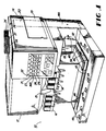
- Figs. 1 and 2 are perspective views of the automatic postmix beverage dispenser 10 according to the present invention.
- the dispenser 10 includes an ice bin module 12 having a plurality of single flavor, manual valves 14 and an ice dispenser 15, and an automatic dispense module 16 having an automatic multiflavor valve 18 (alternatively, two or more multiflavor valves 18 can be located at this position).
- the ice bin module 12 includes the usual syrup lines, carbonated water lines, still water line(s), and cold plate for cooling the syrup and water lines leading to the valves 14, which can be any known valves.
- the automatic dispense module 16 is attached to the ice bin module, receives ice therefrom, and includes a cabinet 20, a front panel 168 thereon with a plurality of lights and buttons and a door 35 (for access in case of a cup jam).
- the front panel includes a series of beverage selector buttons 21, a corresponding "syrup out" light 22 above each button 21, and small, medium, and large buttons 23, 24 and 25 respectively below each beverage selector button 21.
- the front panel may have other buttons and lights as desired for an automatic beverage dispenser.
- the automatic dispenser module 16 includes a plurality of syrup lines, a carbonated water line, and a still water line connected to the multiflavor valve 18, which can be any known multiflavor valve. These lines are cooled by the cold plate cooling means in the ice bin module 12.
- the automatic dispense module 16 also includes a cup drop mechanism 34 (any known mechanism can be used) for three different sizes of cups 36, 37 and 38, a cup drop chute 40, an ice drop mechanism for dropping ice into a dropped cup (any known mechanism can be used), a conveyor 42 including first and second conveyor means 44 and 46, and flavor indicating means including a plurality of flavor indicia 48 located one each adjacent a respective one of a plurality of cup pick-up stations 50 A-G corresponding to cup positions 3-9.
- the conveyor 42 also provides a cup drop and ice drop station 52 and a beverage dispense station 54. Cup position 1 is the cup and ice drop station 52, and cup position 2 is the beverage dispense station 54.
- the first conveyor means 44 moves the cup forward from position 1 to position 4.
- This first conveyor means 42 includes a cup support surface 56 including several parallel rods 58 and a cup moving means 59.
- the cup moving means includes a stationary rod 60 and a movable sleeve 62 slidable on rod 60.
- the sleeve 62 is also accurately movable to rotate a plurality of cup engaging arms 64 into and out of cup engagement.
- the linear movement of the sleeve 62 is caused by a moveable piston 66 in a stationary cylinder 68.
- the piston 66 is connected to an arm actuator block 70 which is also connected to the sleeve 62 to move the sleeve 62 one cup position at a time each time the pneumatic piston 66 is energized.
- an arm rotator cylinder 72 is pivotably attached to the block 70 and its piston 74 is attached to a sleeve arm 76.
- the block 70 has a proximity switch 78 and the sleeve 62 includes a magnet 80 so the control system will know the position of the arms 64.
- An elastic boot 82 (shown cut away in Fig. 2) surrounds the rod 60 and extends between the sleeve 62 and a rod support 84.
- the second conveyor means 46 includes a cup support surface 90 comprising several parallel rods 92 and the cup moving means 94 includes a stationary support 96 connected to a pneumatic cylinder 98 having a movable piston 100 connected to a movable support 102 holding a plurality of pneumatic cylinders C-1, C-2, C-3, and C-4 each having a retractable cup-engaging pin 121, 122, 123, and 124.
- one additional, fixed, cup-engaging pin 104 is connected to a support member 106 mounted on the movable support 102.
- Each of the pneumatic cylinders 68, 72, C-1, C-2, C-3, C-4, and 98 in the conveyor 42 are preferably double acting cylinders controlled by solenoids in the gas lines, the solenoids all being preferably located behind the front panel 168.
- the conveyor 42 includes a plurality of limit switches for use in controlling the conveyor.
- the first conveyor means first must rotate to bring the arms 64 into cup engaging position before the pneumatic cylinder 68 moves the conveyor one cup position, then it must rotate back before the cylinder returns the conveyor to its original position.
- the limit switches determine that all prerequisites have occurred before the next step can be taken.
- the conveyor means 44 can not advance or dispense another beverage. If a cup is removed from position P-7, for example, conveyor 46 will advance the cups at P-6, P-5, and P-4 one position forward to fill the gap, and then conveyor 44 can also move forward one position and can dispense another beverage. There is no photoeye at cup positions P-2 and P-3.
- the control system can store 16 orders in the dispenser and more can be stored in the point of sale adapter.
- the flavor indicating means preferably includes a flavor indicia 48 at each cup pick-up station (positions 3-9) and means for energizing these indicia and for scrolling them every time the conveyor 42 advances cups one position.
- the term "scrolling" means that the flavor indicia changes to now indicate the flavor in the new cup that has just arrived at that cup pick-up station.
- the new indicia will be the same. In this way, the indicia properly follows a cup along the conveyor until it is removed by an operator at which time the light will go out.
- a second indicator such as a lighted display, can be included at each station to indicate the order number of the drink such as 27, for example.
- the dispenser 10 also includes a system for eliminating warm casual drinks. This system is shown schematically in Fig. 7.
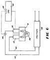
- Fig. 6 is a partial schematic showing of multiflavor beverage dispensing valve 18, and shows a syrup solenoid valve 132, a water solenoid valve 134, a spout 136, a cold plate 138, a syrup line 140, a water line 142, a CPU 144, and a thermometer 146 in the water line.
- the CPU includes a timer circuit or clock 148. The CPU is programmed such that when a beverage is requested, it will review how much time has elapsed since the last dispense cycle, and if it exceeds a particular value, such as 15 minutes, a purge cycle will be initialed before the requested beverage can be dispensed. It preferably then opens the water solenoid valve while leaving the syrup solenoid valve closed, for a period of time, such as 5 seconds, to allow the water in the uncooled position of the water line to drain out.
- the thermometer 146 is not used in the preferred system.
- thermometer 146 is included and when a new drink is requested, if the temperature is above a selected value, such as 40° F, the water is purged until the temperature is reduced to a desired value, such as 38° F.
- a selected value such as 40° F
- the casual drink purge system of this invention is preferably applied only to the multiflavor valve 18 and not to the manual valves 14, although it could be applied to manual valves, if desired.
- an inexpensive timer can be used to purge a manual valve for 5 seconds every time 15 minutes elapses since the last dispense cycle.
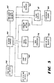
- Fig. 3 is a simplified block diagram of the system of the present invention.
- the system includes an on-board computer 160 (which is preferably located in the rear of the automatic dispense module 16, as shown in Fig. 1) connected to all of the water and syrup solenoids 162 in the multiflavor valve 18, the air solenoids 164 in the conveyor 42, the LEDs in the flavor indicia 48, the temperature sensor 146 (in the embodiment in which one is used), syrup sold-out switches 166 connected to corresponding lights on a front panel 168 on the automatic dispense module 16, a keyboard 170 on the front panel 168, conveyor limit switches 172, and a point of sale register 174 which can, if desired, be connected to the computer 160 through a data conversion system 176 and an RS 232 adapter to operate the automatic dispenser 10 directly from the point of sale register 174 on the counter that is used by the operators when taking orders.
- an on-board computer 160 which is preferably located in the rear of the automatic dispense module 16, as shown in Fig.
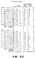
- Figs. 4-4H are the wiring diagrams for connection of external devices to the GE Series One Plus controller used in the preferred embodiment of the automatic dispenser 10 as follows:
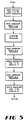
- Fig. 5 is a block flow diagram of the operation of the flavor indicia.
- the automatic dispenser 10 has the ability to prepare soft drinks from a variety of different flavor selections. It is quite likely that several of the flavors have similar visual appearance in the cup, making it difficult for the operator to distinguish one flavor drink from another.
- the automatic dispenser 10 solves this problem by employing a display element (flavor indicia 48) at each drink pickup position (cup pick-up station 50A-50G, also known as cup positions P-3 to P-9).
- the display is a 7-segment LED with decimal.
- Each flavor is given a unique code to be shown on the display, for example, "C” of cola, "d” for diet cola, and "O" for orange.
- codes are created by assigning each segment of the display to a bit in an 8-bit data word in the controller.
- the code is created by defining the segments to be turned on, and considering the bit value for the segment to be "1". This binary representation is then converted to decimal for handling purposes in the controller.
- the automatic dispenser 10 controller maintains a record of the display codes of drinks dispensed in a shift register format.
- the shift register is incremented each time the conveyor 42 moves a cup to a new position.
- the value of the shift register for positions 3 and higher is converted back to binary, and written to an output that is connected to the associated LED display. Therefore, as a cup is moved on the conveyor 43, its display code is shifted to the associated display element.
- These photoeyes 110 are also used by the automatic dispenser 10 controller to blank the display at the conveyor position when a cup is removed. If a cup is removed, but no other cup has yet been advanced to that position, the display code may be recalled by placing the cup back on the conveyor momentarily. This is useful if the operator who removed the cup is distracted, and cannot remember the flavor in the
- Fig. 8 is a block diagram of the purge timer logic used in the warm water purge system of the present invention.
- the purge timer function of the automatic dispenser 10 is intended to provide properly chilled soda water at the automatic dispenser dispensing valve 18 before a drink is poured. This is necessary to insure the quality of the beverage to be poured, as the soda temperature is directly related to the amount of carbonation retained, the amount of foam dispensed and the amount of ice melted in the cup. This function is controlled by the programmable controller that operates the automatic dispenser 10.
- the purge function in the automatic dispenser 10 operates as a pair of timing functions.
- the Draw Timer is the master element in the process. This timer is reset every time a drink is dispensed from the valve 18 of the automatic dispenser 10.
- the Draw Timer has a timeout of 15 minutes in the preferred embodiment.
- the next call to dispense a drink will operate the purge function.
- this call occurs when a cup has been dropped into the cup drop and ice drop station (also referred to as position 1), and filled with ice, but before the cup is moved to the beverage dispense station (also referred to as position 2) by the conveyor 42.
- the Purge Timer is used to control the duration of the purge, once it is initiated.
- the Purge Timer has a timeout of 5 seconds.
- the soda solenoid valve 134 in the automatic dispenser 10 valve 18 is opened for the duration of the Purge Time, allowing the purge to be dispensed into the drain of the automatic dispenser.
- the conveyor 42 is allowed to move the cup to the beverage dispense station (position 2), and normal operation resumes.
Landscapes
- Devices For Dispensing Beverages (AREA)
- Tea And Coffee (AREA)
Claims (7)
- Vorrichtung, welche aufweist:(a) einen automatischen Spender für Mischgetränke;(b) der Spender ein automatisches Getränkeausgabeventil umfaßt, welches ein magnetisch gesteuertes Wasserventil und ein magnetisch gesteuertes Sirupventil umfaßt;(c) eine Sirupleitung im Spender, welche mit dem Getränkeausgabeventil verbunden ist;(d) eine Wasserleitung im Spender, welche mit dem Getränkeausgabeventil verbunden ist;(e) der Spender eine Kühleinrichtung zum Kühlen der Sirupleitung und der Wasserleitung, abgesehen von einem ungekühlten Teil der Leitungen umfaßt, welches zwischen der Kühleinrichtung und dem Ventil verläuft;(f) eine Spüleinrichtung zum Öffnen des Wasserventils eine Zeitperiode lang und dann zum Schließen des Wasserventils, währenddem das Sirupventil geschlossen bleibt, um Warmwasser aus dem ungekühlten Teil der Wasserleitung abzugeben; und(g) der automatische Spender einen eingebauten Computer und einen Getränkeausgabeschalter umfaßt, und wobei die Spüleinrichtung eine Zeitgeberschaltung im Computer umfaßt, welche die Zeitdauer seit der letzten Abgabe von dem Getränkeausgabeventil mißt, sowie eine Einrichtung nur zum Öffnen des Wasserventils, wenn der Schalter geschlossen ist und die mit Hilfe der Zeitgeberschaltung gemessene Zeit einen vorbestimmten Wert überschreitet.
- Vorrichtung nach Anspruch 1, bei der der vorbestimmte Wert sich auf etwa 15 Minuten beläuft.
- Vorrichtung nach Anspruch 1, bei der der automatische Spender auch ein Thermometer zum Messen der Temperatur des Wassers in dem ungekühlten Teil der Wasserleitung umfaßt, und bei der die Spüleinrichtung eine Einrichtung zum Öffnen des Wasserventils umfaßt, bis die Temperatur des Wassers im ungekühlten Teil der Wasserleitung auf einen vorbestimmten Wert abfällt.
- Vorrichtung nach Anspruch 1, bei der die Spüleinrichtung eine Einrichtung zum Öffnen des Wasserventils für eine vorbestimmte Zeitperiode umfaßt.
- Vorrichtung nach Anspruch 4, bei der die vorbestimmte Zeitperiode sich auf etwa 5 Sekunden beläuft.
- Vorrichtung nach Anspruch 1, bei der das Getränkeausgabeventil ein Mehrgeschmacksventil ist.
- Verfahren zum Verhindern der Ausgabe eines warmen, unbrauchbaren Getränks aus einem automatischen Spender für Mischgetränke, welches die folgenden Schritte aufweist:(a) Versehen eines automatischen Spenders für Mischgetränke mit einem Getränkeausgabeventil, welches ein magnetisch gesteuertes Wasserventil und ein magnetisch gesteuertes Sirupventil umfaßt;(b) Vorsehen einer Wasserleitung und einer Sirupleitung im Spender, welche zu dem Getränkeausgabeventil gehen;(c) Vorsehen einer Kühleinrichtung im Spender zum Kühlen der Leitungen, abgesehen von einem ungekühlten Teil der Leitung zwischen der Kühleinrichtung und dem Getränkeausgabeventil;(d) Ausspülen des Wassers aus dem ungekühlten Teil der Wasserleitung lediglich durch Öffnen des Wasserventils während das Sirupventil geschlossen bleibt, um Wasser aus dem ungekühlten Teil der Wasserleitung abzuleiten; und(e) Messen der Zeitgröße seit der letzten Ausgabe aus dem Getränkeausgabeventil, wenn eine neue Ausgabe angefordert wird und Durchführen des Ausspülschrittes nur dann, wenn die gemessene Zeit einen vorbestimmten Wert überschreitet.
Priority Applications (1)
| Application Number | Priority Date | Filing Date | Title |
|---|---|---|---|
| AT90904122T ATE96409T1 (de) | 1989-02-27 | 1990-02-26 | Post-mix-getraenkespender mit warmwasserablauf. |
Applications Claiming Priority (2)
| Application Number | Priority Date | Filing Date | Title |
|---|---|---|---|
| US316364 | 1989-02-27 | ||
| US07/316,364 US4967932A (en) | 1989-02-27 | 1989-02-27 | Postmix beverage dispensing system with warm water purging and method |
Publications (2)
| Publication Number | Publication Date |
|---|---|
| EP0460068A1 EP0460068A1 (de) | 1991-12-11 |
| EP0460068B1 true EP0460068B1 (de) | 1993-10-27 |
Family
ID=23228749
Family Applications (1)
| Application Number | Title | Priority Date | Filing Date |
|---|---|---|---|
| EP90904122A Expired - Lifetime EP0460068B1 (de) | 1989-02-27 | 1990-02-26 | Post-mix-getränkespender mit warmwasserablauf |
Country Status (10)
| Country | Link |
|---|---|
| US (1) | US4967932A (de) |
| EP (1) | EP0460068B1 (de) |
| JP (1) | JPH04503648A (de) |
| AU (1) | AU632546B2 (de) |
| BR (1) | BR9007172A (de) |
| CA (1) | CA2048617A1 (de) |
| DE (1) | DE69004251T2 (de) |
| ES (1) | ES2047918T3 (de) |
| PH (1) | PH26657A (de) |
| WO (1) | WO1990009952A1 (de) |
Families Citing this family (44)
| Publication number | Priority date | Publication date | Assignee | Title |
|---|---|---|---|---|
| US5115942A (en) * | 1988-12-15 | 1992-05-26 | Imi Cornelius Inc. | Method and apparatus for dispensing cold beverage |
| US5360140A (en) * | 1988-12-16 | 1994-11-01 | The Cornelius Company | Low cost control circuit for sensing the operation of an electrically operable device |
| GB8901864D0 (en) * | 1989-01-27 | 1989-03-15 | Imi Cornelius Uk Ltd | Beverage dispensing apparatus |
| US5072859A (en) * | 1989-02-27 | 1991-12-17 | The Coca-Cola Company | Beverage dispensing system with clear dring purge and method |
| US5141130A (en) * | 1989-02-27 | 1992-08-25 | The Coca-Cola Company | Beverage dispensing system with warm water purging |
| DE4022492C1 (de) * | 1990-07-14 | 1991-06-13 | Draegerwerk Ag, 2400 Luebeck, De | |
| US5350082A (en) * | 1992-11-09 | 1994-09-27 | Alex Kiriakides, Jr. | Automatic soda fountain and method |
| IL119044A (en) * | 1996-08-08 | 2004-09-27 | Shemuel Amitai | Water carbonating device |
| US5839291A (en) * | 1996-08-14 | 1998-11-24 | Multiplex Company, Inc. | Beverage cooling and dispensing system with diagnostics |
| US6393966B1 (en) * | 1997-04-18 | 2002-05-28 | Bunn-O-Matic Corporation | Beverage server |
| US8534187B2 (en) * | 1997-04-18 | 2013-09-17 | Bunn-O-Matic Corporation | Beverage server |
| US20080073610A1 (en) * | 1997-08-22 | 2008-03-27 | Manning Casey P | Stopcock valve |
| KR100246399B1 (ko) * | 1997-09-23 | 2000-04-01 | 구자홍 | 냉장고용 디스펜서어셈블리 및 그 제어방법 |
| US6053359A (en) * | 1997-12-22 | 2000-04-25 | Mcdonald's Corporation | Automated beverage system |
| US6685059B2 (en) | 2000-09-29 | 2004-02-03 | Pepsico, Inc. | Brewed iced tea or non-carbonated drink dispenser |
| US6883685B2 (en) | 2001-03-19 | 2005-04-26 | Pepsico, Inc. | Brewed iced tea or non-carbonated drink dispenser with quiet operation |
| US6641723B2 (en) * | 2001-05-25 | 2003-11-04 | Oxygen8, Inc. | Oxygenated water dispensing system and method |
| US20060006195A1 (en) * | 2001-10-01 | 2006-01-12 | Jones Brian C | Method and apparatus for producing a tea beverage employing a continuous mixing chamber |
| US6915732B2 (en) * | 2003-04-01 | 2005-07-12 | Pepsico, Inc. | Brewed iced tea or non-carbonated drink dispenser |
| US11906988B2 (en) | 2006-03-06 | 2024-02-20 | Deka Products Limited Partnership | Product dispensing system |
| US7905373B2 (en) * | 2006-03-06 | 2011-03-15 | Deka Products Limited Partnership | System and method for generating a drive signal |
| US9146564B2 (en) | 2006-03-06 | 2015-09-29 | Deka Products Limited Partnership | Product dispensing system |
| US11214476B2 (en) | 2006-03-06 | 2022-01-04 | Deka Products Limited Partnership | System and method for generating a drive signal |
| US11634311B2 (en) | 2007-09-06 | 2023-04-25 | Deka Products Limited Partnership | Product dispensing system |
| US10859072B2 (en) | 2007-09-06 | 2020-12-08 | Deka Products Limited Partnership | Product dispensing system |
| CN103848388A (zh) * | 2007-09-06 | 2014-06-11 | 德卡产品有限公司 | 饮料配给系统 |
| US10562757B2 (en) | 2007-09-06 | 2020-02-18 | Deka Products Limited Partnership | Product dispensing system |
| US12135019B2 (en) | 2007-09-06 | 2024-11-05 | Deka Products Limited Partnership | Product dispensing system |
| WO2010025382A2 (en) | 2008-08-28 | 2010-03-04 | Deka Products Limited Partnership | Product dispensing system |
| US9622615B2 (en) * | 2008-11-10 | 2017-04-18 | Automatic Bar Controls, Inc. | Touch screen interface for a beverage dispensing machine |
| GB2474741B (en) * | 2009-08-21 | 2012-03-07 | Schroeder Ind Inc | Beverage dispensing apparatus |
| IT1401822B1 (it) * | 2010-09-24 | 2013-08-28 | Casadio Prati | Distributore automatico, particolarmente per bevande fredde. |
| WO2013044213A1 (en) * | 2011-09-22 | 2013-03-28 | Imi Cornelius Inc. | Beverage dispensing apparatus |
| AU2013205574B2 (en) * | 2012-02-27 | 2014-12-11 | The Coca-Cola Company | Automated beverage dispensing system with ice and beverage dispensing |
| RU2727048C2 (ru) | 2015-01-30 | 2020-07-17 | Анхойзер-Буш Инбев С.А. | Концентраты напитков под давлением, а также устройства и способы получения напитков из указанных концентратов |
| US20180290113A1 (en) * | 2015-01-30 | 2018-10-11 | Anheuser-Busch Inbev S.A. | Methods, Appliances, and Systems for Preparing a Beverage from a Base Liquid and an Ingredient |
| WO2016164780A1 (en) * | 2015-04-10 | 2016-10-13 | Cornelius, Inc. | Multiple flavor beverage dispenser |
| US10252904B2 (en) | 2016-09-12 | 2019-04-09 | Cornelius, Inc. | Systems and methods of custom condiment dispensing |
| US10315236B2 (en) | 2016-10-25 | 2019-06-11 | Cornelius, Inc. | Systems and methods of food dispenser cleaning |
| WO2018085280A1 (en) | 2016-11-01 | 2018-05-11 | Cornelius Inc. | Dispensing nozzle |
| ES2684532B1 (es) * | 2017-03-30 | 2019-07-10 | Pineiro Juan Jose Tubio | Sistema de dispensing inteligente |
| US11135345B2 (en) | 2017-05-10 | 2021-10-05 | Fresenius Medical Care Holdings, Inc. | On demand dialysate mixing using concentrates |
| US11748827B2 (en) | 2018-08-06 | 2023-09-05 | Marmon Foodservice Technologies, Inc. | Order fulfillment system |
| US11504458B2 (en) | 2018-10-17 | 2022-11-22 | Fresenius Medical Care Holdings, Inc. | Ultrasonic authentication for dialysis |
Family Cites Families (15)
| Publication number | Priority date | Publication date | Assignee | Title |
|---|---|---|---|---|
| US2830528A (en) * | 1954-05-03 | 1958-04-15 | United Coffee Corp | Beverage brewing and dispensing apparatus |
| US3570715A (en) * | 1968-11-07 | 1971-03-16 | Anders Evers | Dispensing system |
| US3898861A (en) * | 1973-08-20 | 1975-08-12 | Cornelius Co | Beverage dispenser |
| US4216879A (en) * | 1978-08-16 | 1980-08-12 | The Cornelius Company | Method of and apparatus for dispensing a high volumetric flow rate of carbonated beverage, having partial reversal of a circulating flow |
| NL7809471A (nl) * | 1978-09-18 | 1980-03-20 | Friesland Condensfab | Inrichting voor het bereiden van gekoelde of warme en gekoelde dranken uit poeder en water. |
| US4285446A (en) * | 1979-06-22 | 1981-08-25 | Ransburg Corporation | Automatic purging system having a pressure sensor and a timing mechanism |
| US4535917A (en) * | 1981-02-13 | 1985-08-20 | Multiplex Company, Inc. | Dispensing apparatus |
| GB8304441D0 (en) * | 1983-02-17 | 1983-03-23 | Ruskin B E S | Beverage dispensing apparatus |
| JPS6146686U (ja) * | 1984-08-31 | 1986-03-28 | サンデン株式会社 | 飲料販売機 |
| US4610145A (en) * | 1984-09-21 | 1986-09-09 | Arzberger William A | Post mix fruit juice dispenser |
| CA1261642A (en) * | 1985-08-26 | 1989-09-26 | John R. Mcmillin | Post-mix beverage dispenser with nozzle flush |
| US4688699A (en) * | 1985-10-02 | 1987-08-25 | Autotrol Corporation | Bactericidal mixture control system having flow and dispense duration controls for respective substances |
| US4730463A (en) * | 1986-05-05 | 1988-03-15 | Stanfill Ted M | Beverage dispenser cooling system |
| GB8611389D0 (en) * | 1986-05-09 | 1986-06-18 | Cadbury Schweppes Plc | Carbonating apparatus |
| US4801375A (en) * | 1987-02-17 | 1989-01-31 | Cuno Incorporated | Water vending system |
-
1989
- 1989-02-27 US US07/316,364 patent/US4967932A/en not_active Expired - Fee Related
-
1990
- 1990-02-26 DE DE90904122T patent/DE69004251T2/de not_active Expired - Fee Related
- 1990-02-26 WO PCT/US1990/000992 patent/WO1990009952A1/en not_active Ceased
- 1990-02-26 EP EP90904122A patent/EP0460068B1/de not_active Expired - Lifetime
- 1990-02-26 ES ES90904122T patent/ES2047918T3/es not_active Expired - Lifetime
- 1990-02-26 JP JP2504415A patent/JPH04503648A/ja active Pending
- 1990-02-26 BR BR909007172A patent/BR9007172A/pt not_active IP Right Cessation
- 1990-02-26 PH PH40115A patent/PH26657A/en unknown
- 1990-02-26 CA CA002048617A patent/CA2048617A1/en not_active Abandoned
- 1990-02-26 AU AU51943/90A patent/AU632546B2/en not_active Ceased
Also Published As
| Publication number | Publication date |
|---|---|
| US4967932A (en) | 1990-11-06 |
| AU5194390A (en) | 1990-09-26 |
| ES2047918T3 (es) | 1994-03-01 |
| PH26657A (en) | 1992-09-04 |
| JPH04503648A (ja) | 1992-07-02 |
| EP0460068A1 (de) | 1991-12-11 |
| DE69004251T2 (de) | 1994-05-11 |
| DE69004251D1 (de) | 1993-12-02 |
| BR9007172A (pt) | 1991-12-17 |
| CA2048617A1 (en) | 1990-08-28 |
| AU632546B2 (en) | 1993-01-07 |
| WO1990009952A1 (en) | 1990-09-07 |
Similar Documents
| Publication | Publication Date | Title |
|---|---|---|
| EP0460068B1 (de) | Post-mix-getränkespender mit warmwasserablauf | |
| US5141130A (en) | Beverage dispensing system with warm water purging | |
| US5058630A (en) | Automatic beverage dispensing system with programmable cup drop | |
| EP0460093B1 (de) | Automatische postmix-getränkeabgabevorrichtung mit geschmacksindikator | |
| EP0528983B1 (de) | Getränkeabgabevorrichtung und verfahren zum betreiben der vorrichtung | |
| US5074341A (en) | Automatic beverage dispensing system | |
| EP1199279B1 (de) | Becherförderer für automatische Getränkeabgabevorrichtung | |
| US4944337A (en) | Automatic beverage dispensing system with plural conveyors | |
| US20080308176A1 (en) | Automated liquid dispensing system | |
| US4677777A (en) | Price setting and display system for multiple unit merchandising machine | |
| US4961447A (en) | Automatic beverge dispensing system | |
| US4967808A (en) | Automatic beverage dispensing system | |
| WO1991017946A1 (en) | Beverage dispensing system with temperature based purge | |
| AU1009102A (en) | Automated beverage system |
Legal Events
| Date | Code | Title | Description |
|---|---|---|---|
| PUAI | Public reference made under article 153(3) epc to a published international application that has entered the european phase |
Free format text: ORIGINAL CODE: 0009012 |
|
| 17P | Request for examination filed |
Effective date: 19910831 |
|
| AK | Designated contracting states |
Kind code of ref document: A1 Designated state(s): AT BE CH DE DK ES FR GB IT LI LU NL SE |
|
| 17Q | First examination report despatched |
Effective date: 19930127 |
|
| GRAA | (expected) grant |
Free format text: ORIGINAL CODE: 0009210 |
|
| AK | Designated contracting states |
Kind code of ref document: B1 Designated state(s): AT BE CH DE DK ES FR GB IT LI LU NL SE |
|
| PG25 | Lapsed in a contracting state [announced via postgrant information from national office to epo] |
Ref country code: SE Effective date: 19931027 Ref country code: NL Effective date: 19931027 Ref country code: LI Effective date: 19931027 Ref country code: DK Effective date: 19931027 Ref country code: CH Effective date: 19931027 Ref country code: BE Effective date: 19931027 Ref country code: AT Effective date: 19931027 |
|
| REF | Corresponds to: |
Ref document number: 96409 Country of ref document: AT Date of ref document: 19931115 Kind code of ref document: T |
|
| REF | Corresponds to: |
Ref document number: 69004251 Country of ref document: DE Date of ref document: 19931202 |
|
| ITF | It: translation for a ep patent filed | ||
| REG | Reference to a national code |
Ref country code: CH Ref legal event code: PL |
|
| ET | Fr: translation filed | ||
| PG25 | Lapsed in a contracting state [announced via postgrant information from national office to epo] |
Ref country code: LU Free format text: LAPSE BECAUSE OF NON-PAYMENT OF DUE FEES Effective date: 19940228 |
|
| REG | Reference to a national code |
Ref country code: ES Ref legal event code: FG2A Ref document number: 2047918 Country of ref document: ES Kind code of ref document: T3 |
|
| NLV1 | Nl: lapsed or annulled due to failure to fulfill the requirements of art. 29p and 29m of the patents act | ||
| PLBE | No opposition filed within time limit |
Free format text: ORIGINAL CODE: 0009261 |
|
| STAA | Information on the status of an ep patent application or granted ep patent |
Free format text: STATUS: NO OPPOSITION FILED WITHIN TIME LIMIT |
|
| 26N | No opposition filed | ||
| PGFP | Annual fee paid to national office [announced via postgrant information from national office to epo] |
Ref country code: ES Payment date: 19950117 Year of fee payment: 6 |
|
| PGFP | Annual fee paid to national office [announced via postgrant information from national office to epo] |
Ref country code: FR Payment date: 19950227 Year of fee payment: 6 |
|
| PG25 | Lapsed in a contracting state [announced via postgrant information from national office to epo] |
Ref country code: ES Free format text: LAPSE BECAUSE OF NON-PAYMENT OF DUE FEES Effective date: 19960227 |
|
| PG25 | Lapsed in a contracting state [announced via postgrant information from national office to epo] |
Ref country code: FR Effective date: 19961031 |
|
| REG | Reference to a national code |
Ref country code: FR Ref legal event code: ST |
|
| REG | Reference to a national code |
Ref country code: ES Ref legal event code: FD2A Effective date: 19990301 |
|
| REG | Reference to a national code |
Ref country code: GB Ref legal event code: IF02 |
|
| PGFP | Annual fee paid to national office [announced via postgrant information from national office to epo] |
Ref country code: DE Payment date: 20050208 Year of fee payment: 16 |
|
| PGFP | Annual fee paid to national office [announced via postgrant information from national office to epo] |
Ref country code: GB Payment date: 20050214 Year of fee payment: 16 |
|
| PG25 | Lapsed in a contracting state [announced via postgrant information from national office to epo] |
Ref country code: IT Free format text: LAPSE BECAUSE OF NON-PAYMENT OF DUE FEES;WARNING: LAPSES OF ITALIAN PATENTS WITH EFFECTIVE DATE BEFORE 2007 MAY HAVE OCCURRED AT ANY TIME BEFORE 2007. THE CORRECT EFFECTIVE DATE MAY BE DIFFERENT FROM THE ONE RECORDED. Effective date: 20050226 |
|
| PG25 | Lapsed in a contracting state [announced via postgrant information from national office to epo] |
Ref country code: GB Free format text: LAPSE BECAUSE OF NON-PAYMENT OF DUE FEES Effective date: 20060226 |
|
| PG25 | Lapsed in a contracting state [announced via postgrant information from national office to epo] |
Ref country code: DE Free format text: LAPSE BECAUSE OF NON-PAYMENT OF DUE FEES Effective date: 20060901 |
|
| GBPC | Gb: european patent ceased through non-payment of renewal fee |
Effective date: 20060226 |