EP0460310B1 - Procédé et appareil pour la réception de matière non tissée - Google Patents
Procédé et appareil pour la réception de matière non tissée Download PDFInfo
- Publication number
- EP0460310B1 EP0460310B1 EP90306130A EP90306130A EP0460310B1 EP 0460310 B1 EP0460310 B1 EP 0460310B1 EP 90306130 A EP90306130 A EP 90306130A EP 90306130 A EP90306130 A EP 90306130A EP 0460310 B1 EP0460310 B1 EP 0460310B1
- Authority
- EP
- European Patent Office
- Prior art keywords
- drum
- air
- screen
- inlets
- stationary
- Prior art date
- Legal status (The legal status is an assumption and is not a legal conclusion. Google has not performed a legal analysis and makes no representation as to the accuracy of the status listed.)
- Expired - Lifetime
Links
- 238000000034 method Methods 0.000 title claims description 13
- 239000000835 fiber Substances 0.000 claims description 31
- 238000005192 partition Methods 0.000 claims description 16
- 238000007664 blowing Methods 0.000 claims description 11
- 239000000155 melt Substances 0.000 description 7
- 229920005989 resin Polymers 0.000 description 4
- 239000011347 resin Substances 0.000 description 4
- 238000010276 construction Methods 0.000 description 3
- 230000008878 coupling Effects 0.000 description 2
- 238000010168 coupling process Methods 0.000 description 2
- 238000005859 coupling reaction Methods 0.000 description 2
- 238000005520 cutting process Methods 0.000 description 2
- 238000010438 heat treatment Methods 0.000 description 2
- 239000004750 melt-blown nonwoven Substances 0.000 description 2
- 229920000642 polymer Polymers 0.000 description 2
- VGGSQFUCUMXWEO-UHFFFAOYSA-N Ethene Chemical compound C=C VGGSQFUCUMXWEO-UHFFFAOYSA-N 0.000 description 1
- 239000005977 Ethylene Substances 0.000 description 1
- 239000004677 Nylon Substances 0.000 description 1
- 239000004952 Polyamide Substances 0.000 description 1
- 239000004743 Polypropylene Substances 0.000 description 1
- 239000004793 Polystyrene Substances 0.000 description 1
- 229910000831 Steel Inorganic materials 0.000 description 1
- 230000002238 attenuated effect Effects 0.000 description 1
- 230000015572 biosynthetic process Effects 0.000 description 1
- 238000007599 discharging Methods 0.000 description 1
- 230000000694 effects Effects 0.000 description 1
- 230000003028 elevating effect Effects 0.000 description 1
- 229920001038 ethylene copolymer Polymers 0.000 description 1
- 229920001903 high density polyethylene Polymers 0.000 description 1
- 239000004700 high-density polyethylene Substances 0.000 description 1
- 238000003780 insertion Methods 0.000 description 1
- 230000037431 insertion Effects 0.000 description 1
- 229920001684 low density polyethylene Polymers 0.000 description 1
- 239000004702 low-density polyethylene Substances 0.000 description 1
- 238000004519 manufacturing process Methods 0.000 description 1
- 239000002184 metal Substances 0.000 description 1
- 239000000203 mixture Substances 0.000 description 1
- 229920001778 nylon Polymers 0.000 description 1
- 230000002093 peripheral effect Effects 0.000 description 1
- 229920003229 poly(methyl methacrylate) Polymers 0.000 description 1
- 229920002647 polyamide Polymers 0.000 description 1
- 239000004417 polycarbonate Substances 0.000 description 1
- 229920000515 polycarbonate Polymers 0.000 description 1
- 229920000728 polyester Polymers 0.000 description 1
- 239000004926 polymethyl methacrylate Substances 0.000 description 1
- -1 polypropylene Polymers 0.000 description 1
- 229920001155 polypropylene Polymers 0.000 description 1
- 229920001296 polysiloxane Polymers 0.000 description 1
- 229920002223 polystyrene Polymers 0.000 description 1
- 239000004814 polyurethane Substances 0.000 description 1
- 229920002635 polyurethane Polymers 0.000 description 1
- 238000004513 sizing Methods 0.000 description 1
- 239000007787 solid Substances 0.000 description 1
- 239000010959 steel Substances 0.000 description 1
- 229920001169 thermoplastic Polymers 0.000 description 1
- 229920005992 thermoplastic resin Polymers 0.000 description 1
- 239000004416 thermosoftening plastic Substances 0.000 description 1
- 238000003466 welding Methods 0.000 description 1
Images



Classifications
-
- D—TEXTILES; PAPER
- D04—BRAIDING; LACE-MAKING; KNITTING; TRIMMINGS; NON-WOVEN FABRICS
- D04H—MAKING TEXTILE FABRICS, e.g. FROM FIBRES OR FILAMENTARY MATERIAL; FABRICS MADE BY SUCH PROCESSES OR APPARATUS, e.g. FELTS, NON-WOVEN FABRICS; COTTON-WOOL; WADDING ; NON-WOVEN FABRICS FROM STAPLE FIBRES, FILAMENTS OR YARNS, BONDED WITH AT LEAST ONE WEB-LIKE MATERIAL DURING THEIR CONSOLIDATION
- D04H3/00—Non-woven fabrics formed wholly or mainly of yarns or like filamentary material of substantial length
- D04H3/08—Non-woven fabrics formed wholly or mainly of yarns or like filamentary material of substantial length characterised by the method of strengthening or consolidating
- D04H3/16—Non-woven fabrics formed wholly or mainly of yarns or like filamentary material of substantial length characterised by the method of strengthening or consolidating with bonds between thermoplastic filaments produced in association with filament formation, e.g. immediately following extrusion
-
- D—TEXTILES; PAPER
- D04—BRAIDING; LACE-MAKING; KNITTING; TRIMMINGS; NON-WOVEN FABRICS
- D04H—MAKING TEXTILE FABRICS, e.g. FROM FIBRES OR FILAMENTARY MATERIAL; FABRICS MADE BY SUCH PROCESSES OR APPARATUS, e.g. FELTS, NON-WOVEN FABRICS; COTTON-WOOL; WADDING ; NON-WOVEN FABRICS FROM STAPLE FIBRES, FILAMENTS OR YARNS, BONDED WITH AT LEAST ONE WEB-LIKE MATERIAL DURING THEIR CONSOLIDATION
- D04H1/00—Non-woven fabrics formed wholly or mainly of staple fibres or like relatively short fibres
- D04H1/40—Non-woven fabrics formed wholly or mainly of staple fibres or like relatively short fibres from fleeces or layers composed of fibres without existing or potential cohesive properties
- D04H1/54—Non-woven fabrics formed wholly or mainly of staple fibres or like relatively short fibres from fleeces or layers composed of fibres without existing or potential cohesive properties by welding together the fibres, e.g. by partially melting or dissolving
- D04H1/56—Non-woven fabrics formed wholly or mainly of staple fibres or like relatively short fibres from fleeces or layers composed of fibres without existing or potential cohesive properties by welding together the fibres, e.g. by partially melting or dissolving in association with fibre formation, e.g. immediately following extrusion of staple fibres
-
- D—TEXTILES; PAPER
- D04—BRAIDING; LACE-MAKING; KNITTING; TRIMMINGS; NON-WOVEN FABRICS
- D04H—MAKING TEXTILE FABRICS, e.g. FROM FIBRES OR FILAMENTARY MATERIAL; FABRICS MADE BY SUCH PROCESSES OR APPARATUS, e.g. FELTS, NON-WOVEN FABRICS; COTTON-WOOL; WADDING ; NON-WOVEN FABRICS FROM STAPLE FIBRES, FILAMENTS OR YARNS, BONDED WITH AT LEAST ONE WEB-LIKE MATERIAL DURING THEIR CONSOLIDATION
- D04H1/00—Non-woven fabrics formed wholly or mainly of staple fibres or like relatively short fibres
- D04H1/70—Non-woven fabrics formed wholly or mainly of staple fibres or like relatively short fibres characterised by the method of forming fleeces or layers, e.g. reorientation of fibres
- D04H1/72—Non-woven fabrics formed wholly or mainly of staple fibres or like relatively short fibres characterised by the method of forming fleeces or layers, e.g. reorientation of fibres the fibres being randomly arranged
Definitions
- This invention relates generally to nonwoven webs and more particularly to a method and apparatus for collecting the webs as they are formed.
- the invention relates to a rotary vacuum screen for collecting melt blown nonwoven webs.
- the equipment for carrying out the melt blowing process comprises an extruder, a die, air flow means, a collector screen, a windup drum, as well as ancillary components such as blowers, air heaters, and controls.
- the collector screen as disclosed in US-A-3,825,379 and 3,878,014, is frequently in the form of a rotating screen which collects the web on the surface and permits passage of air into the interior thereof.
- the fibers must be evenly deposited on the collector screen to produce a uniform, high quality nonwoven web.
- One prior art approach for improving the web uniformity involves applying vacuum to the interior of the screen drum to increase the flow of air through the screen. Although the vacuum collector systems have been adequate for some applications, there remains a need for further improvement to produce high quality uniform webs, particularly for webs used as filters.
- apparatus for separating melt blown fibers and air from a meltblowing die assembly comprising:
- a meltblowing process comprising extruding a row of molten fibers; blowing hot air onto both sides of the fibers; collecting the fibers on a rotating screen drum while air flows through the screen into the interior of the screen drum and axially out of the drum, characterised in that the air is flowed through the rotating screen into a stationary drum via a row of side-by-side air inlets formed in said stationary drum and underlying said screen, and is withdrawn from each air inlet to a position axially outside said screen drum by separate outlet conduits, one conduit for each inlet.
- the partitions divide the stationary drum into a plurality of side-by-side compartments, each compartment having an inlet through a longitudinal portion of the air slot, and an outlet to the exterior of the drum.
- the compartment inlets and compartment outlets, respectively, are approximately of the same cross sectional area so that the air flow rate through each compartment is approximately the same for a given differential pressure.
- the compartment inlets and outlets are sized to provide a controlled nonuniform flow along the air inlet slot.
- partitions and hence the number of compartments, will depend on the length of the drum. Generally, the partitions should be spaced 10.1 to 30.5cm (4 to 12 inches) apart along the drum axis. Six to 12 compartments will be satisfactory for most drums.
- the process of the present invention comprises extruding a molten thermoplastic resin to form a plurality of side-by-side fibers; blowing high-velocity, hot gas streams onto opposite sides of the fibers to attenuate and draw down the fibers; and collecting the fibers as a web on a rotating screen as the gas passes through the screen.
- the improvement according to the present invention comprises controlling the air flow into the screen along the length of the screen to provide a predetermined transverse web thickness profile.
- the controlled air flow through the screen is generally uniform along the length of the screen to produce a web of uniform thickness.
- Figure 1 is a simplified and schematic perspective view showing the major components of a melt blowing apparatus, including collector screen of the present invention.
- Figure 2 is a side elevation of the collector screen, shown with portions cut away.
- Figure 3 is a longitudinal cross sectional view of the collector screen shown in Figure 2.
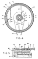
- Figure 4 is a transverse sectional view of the collector screen, with the cutting plane taken along line 4-4 of Figure 3.
- Figure 5 is a cross sectional view of a peripheral portion of the collector screen, with the cutting plane taken along line 5-5 of Figure 4.
- Figure 6 is a side elevation of the collector screen assembly.
- the melt blowing apparatus comprises an extruder 10 for delivering molten resin to a melt blowing die 11 which extrudes a series of side-by-side fibers 12 into converging hot air streams discharging from air slots 13, and a collector drum or screen 15.
- the melt blowing apparatus also includes compressor and air furnace (not shown) for delivering hot air through pipes 14 to the die.
- the die is provided with heating elements 16 and 17 for heating the resin and the air.
- the hot air is conducted through passages formed in the die and discharged as converging sheets of air through slots 13 onto opposite sides of the fibers 12.
- the molten fibers are stretched and blown onto collector screen assembly 15 forming a nonwoven web 17 which is withdrawn by a take up roller (not shown).
- the collector screen assembly 15 has a rotating outer screen which permits the collection of the fibers and formation of web 17 as air passes through the screen and exits through manifold 18. Blower 19 creates a vacuum in manifold 18 and within collector screen assembly 15.
- the extruder, die, and air facilities mentioned above may be generally as described in US-A- 3,978,185, the disclosure of which is incorporated herein by reference.
- the polymers used in melt blowing apparatus includes polypropylene, low and high density polyethylene, ethylene copolymers (e.g. EVA), nylon, polyamides, polyesters, polystyrene, poly-4-methylpentenes-1, polymethylmethacrylate, polytrifluorochloro ethylene, polyurethanes, polycarbonates, silicones, pitch and blends of the above resins and any other resins used in meltblowing.
- EVA ethylene copolymers
- a novel feature of the present invention resides in the construction and operation of the screen assembly 15.
- the assembly 15 is seen to include two main relatively rotating members: an inner stationary drum 21 and outer rotating screen 22.
- the inner stationary drum 21 comprises circular end panels panels 23 and 24 and a cylindrical metal shell 28 which is secured to the outer periphery of end panel 23 and 24 thereby forming a hollow drum.
- An elongate slot 27 (best seen in Figure 2) is formed in shell 28 and extends parallel to the axis of the drum 21.
- the slot 27 extends substantially the entire width of the fiber collection area (described below) and provides an inlet for flow of air into the interior of shell 28.
- the width of the slot 27 may vary within a wide range depending in part on the size of the die 11 and the diameter of the drum 21. Generally, the slot width will be between 7.6 to 30.5 cm (3 to 12 inches), with 10.1 to 20.2 cm (4 to 8 inches) being preferred. Also, as described below, the preferred slot width is adjustable.
- Pipe stubs 25 and 26 secured to panels 23 and 24 extend outwardly therefrom in opposite directions and are mounted on frame 29 as illustrated in Figure 2.
- the pipe mounts may be conventional trunion connections permitting angular adjustment of the drum 21 and the position of slot 27.
- partitions 31 through 39 Mounted in the interior of drum 21 are a plurality of axially spaced circular partitions 31 through 39 which divide the interior of drum 21 into side-by-side compartments 41 through 48.
- Each of the partitions, except middle partition 35 has a central opening permitting flow of air therethrough.
- Partition 35 is solid, dividing the drum 21 into two equal longitudinal halves.
- the partitions divide the air slot 27 into separate inlets, one for each compartment, illustrated as 41a through 48a.
- the compartment inlets 41a through 48a have approximately the same cross sectional flow area.
- each compartment has a pipe member extending axially from its outer most partition to a position outside drum 21.
- pipe stubs 25 and 26 extend axially in opposite directions and provide outlet conduits for compartments 41 and 48, respectively.
- conduits 51, 52, and 53 provide outlets for compartments 42, 43, and 44; and pipe members 54, 55, and 56 provide outlets for compartments 45, 46, and 47.
- Each pipe member conducts air from its compartment to pipe stubs 25 or 26 outside the drum 21.
- the openings in the partitions are sized to fit its associated pipe member.
- the pipe members for each half of the drum 21 are concentrically arranged and terminate outside the interior of the drum 21 where the air intermixes in header zones 65 and 66.
- the fabrication of the panels, partitions, shell and pipe members may be of welded steel construction. This provides rigidity for maintaining the concentric relationship of the pipe members.
- the air outlet conduit for each compartment in one half of the drum 21 is as follows: annular conduit 57 for compartment 41, annular conduit 58 for compartment 42, annular conduit 59 for compartment 43, and conduit 60 for compartment 44.
- the other longitudinal half of the drum 21, likewise is provided with conduits 61, 62, 63, and 64 for compartments 48, 47, 46, and 45, respectively.
- the flow areas of inlets 41a through 48a are approximately the same, and flow areas of outlets 57 through 64 are approximately the same.
- the inlet and outlet of each compartment are approximately the same size (i.e. flow area) as the inlets and outlets of the other compartments, the flow rate (and average flow velocity) through the flow inlets will be approximately the same for a given vacuum applied to pipe members 25 and 26. This provides for generally uniform flow rates across the length of slot 27. This, in turn, produces a web of generally uniform thickness.
- manifold assembly 18 which includes flexible hoses 68 and 69, valves 70 and 71, pipes 72 and 73, and fittings 74, 75, and 76.
- the symmetry of the manifold ensures even air flow from each end of the drum 21.
- Fittings 74 and 75 should be attached to pipe stubs 25 and 26 in such a manner to permit angular adjustment of drum 21 on the support frame 29.
- the assembly above the flexible hoses 68 and 69 are mounted on a support separate from frame 29.
- the manifold and vacuum pump are disposed over the collector screen assembly 15.
- the collector screen 22 is in the form of a screen drum which is concentric to drum 21 and is journaled to pipe member 25 and 26 by mounting sleeves 80 and 81.
- Sleeves 80 and 81 are secured to circular end panels 82 and 83 which define the sides of the collector screen 22.
- Rims 84 and 85 extend inwardly from the outer edges of panels 82 and 83 respectively.
- the edges of a heavy duty screen 90 are welded or otherwise secured to the rims by couplings 86 and 87 which include bolts 88 and 89 for applying a tension to the screen.
- a fine mesh screen 91 sized to separate air from the fibers extends around the heavy duty screen and may be also secured by couplings 86 and 87 by welding.
- Figure 5 illustrates details of the screen mounting assembly.
- outer screen 22 is rotatively driven around stationary drum 21 by drive assembly 92 which may be in the form of a conventional belt or chain drive including motor 99.
- the screen drum 22 is normally rotated at a rate to provide a screen speed of between 0.61 to 91.4 metres / min (2 to 300 fpm), preferably 3 to 61 metres / min (10 to 200 fpm), most preferably 15.2 to 45.7 metres / min (50 to 150 fpm).
- a clearance of from 0.51 to 2.5 mm (.020 to .100) inches between the drums will permit free rotation.
- the screen should have a diameter of between about 25.4 to 101.6 cm (10 to 40 inches).
- the inner drum 21 may include a slot cover 93 illustrated in Figure 4.
- the cover 93 extends substantially the full length of the slot 27 and has the same curvature as shell 28.
- Suitable notched openings 94 in the outer edges of each partition are provided to permit movement of the cover 93 along the interior surface of shell 25.
- Strip gears one shown as 95, are provided at spaced intervals on the inwardly facing side of cover 93.
- a rod 96 extends parallel to cover 93 and is provided with pinion gears 97 which mesh with strip gears 95.
- One end of rod 96 is journaled to panel 24 and the other end extends through panel 23 and may be provided with a socket to permit rotation of rod 96.
- a hole may be provided in panel 82 of the rotating screen 22 which aligns with the socket end of rod 96 thereby permitting insertion of a wrench for adjustment of cover 93.
- Turning of rod 96 clockwise as viewed in Figure 4 causes gears 95 and 97 to move the cover 93 upward reducing the width of slot 27 or closing it completely.
- the gears and socket assembly may be such to lock the cover in its adjusted position.
- the support frame 29 is mounted on an adjustable assembly.
- the assembly shown in Figure 6, comprises a scissors elevator 101 on which the frame 29 is mounted.
- a hydraulic cylinder 102 moves the assembly arms 103 and 104 which raises or lowers the frame 29 with the collector 15 thereon.
- Note the flexible hoses 68 and 69 permit vertical movement.
- Horizontal movement is achieved by providing the elevator assembly 101 with wheels 105 and may include a screw drive assembly (not shown) for adjusting the distance of the screen 22 from the die 11.
- the adjustable mounting assembly is extremely important when aligning large collector screens 15 with the melt blowing die 11.
- the following adjustments are normally required : (1) positioning the collector screen 15 at the proper horizontal position so that the slot 27 is aligned with the row of die orifices; (2) elevating the collector screen to bring the slot 27 into horizontal alignment with the die orifices; (3) adjusting angular position of drum 21 to place the slot 27 at the fiber collection area (i.e. The area on the screen at which the mixed fibers and air intercept the screen 91). Between the die exit and the screen 91, the stream flares out slightly in the vertical direction.
- the angular position of the slot 27 be slightly in advance of the center-line of the fibers and air stream direction shown in Figure 1.
- the horizontal center line of the slot 27 (midpoint of the slot width) is from 0 to 30°, preferably 5 to 15°, in advance of the horizontal center line of the air and fiber stream at the collector screen 91.
- the present invention has been described with references to a collector for achieving a generally uniform thickness web by providing a uniform air flow through the slot. Variations of this embodiment include adjusting the air flow through the slot to achieve a predetermined web profile. This variation may be achieved by providing the blot inlets of different size to effect different flow rate and thereby producing a web of varying (but predetermined) thickness. Also individual slot covers for each compartment are possible.
- the generic concept embodied in the present invention is controlled flow through the slot to achieve a predetermined web thickness profile along the length of the slot.
Landscapes
- Engineering & Computer Science (AREA)
- Textile Engineering (AREA)
- Nonwoven Fabrics (AREA)
- Spinning Methods And Devices For Manufacturing Artificial Fibers (AREA)
Claims (17)
- Appareil pour séparer des fibres fondues et soufflées de l'air provenant d'un assemblage de filière de fusion-soufflage, l'appareil comprenant :(a) un tambour fixe (21) comportant une pluralité d'entrées d'air axialement alignées (41a-48a) formées à sa périphérie pour un alignement avec l'assemblage de filière ;(b) une pluralité de conduits de sortie (57-64) s'étendant de l'intérieur du tambour (21) à une zone collectrice (65-66) à son extérieur axial ;(c) des moyens (41-48) pour interconnecter chaque entrée à une sortie ;(d) un tambour tournant à tamis (22) possédant un tamis à la périphérie (90, 91) recouvrant sensiblement les entrées avec une ouverture de maille destinée à faire passer l'air et à ne pas faire passer les fibres ; et(e) des moyens (19) pour appliquer une dépression aux conduits de sortie à la zone collectrice, si bien que l'air s'écoule à travers chaque conduit d'entrée et de sortie.
- Appareil selon la revendication 1, dans lequel le tambour fixe (21) possède un axe horizontal et une fente horizontale (27) formée à sa périphérie et s'étendant parallèlement audit axe, une pluralité de cloisons (31-39) sont montées dans le tambour fixe, divisant le tambour en une pluralité de compartiments disposés côte à côte (41-48) pour former ladite pluralité d'entrées d'air, une pour chaque compartiment, ladite pluralité de conduits de sortie (57-64) comprend un conduit de sortie s'étendant axialement depuis chaque compartiment jusqu'à un collecteur de sortie (65, 66) situé à l'extérieur dudit tambour fixe ; les entrées de compartiment (41a-48a) et les conduits de sortie (57-64) sont dimensionnés pour procurer une distribution d'écoulement d'air prédéterminée à travers le tambour fixe, et ledit tambour tournant à tamis (22) est monté sur ledit tambour fixe (21), le tamis (90, 91) dudit tambour tournant recouvrant sensiblement la fente du tambour fixe et possédant une ouverture de maille pour séparer les fibres de l'air.
- Appareil selon la revendication 2, dans lequel les entrées de compartiment (41a-48a) et les conduits de sortie (57-64) sont configurés et dimensionnés de sorte que le débit d'air à travers chaque entrée de compartiment est sensiblement identique.
- Appareil selon la revendication 2 ou 3, dans lequel le tambour comprend entre 4 et 12 compartiments (41-48) alignés axialement côte à côte.
- Appareil selon la revendication 2 ou 3, dans lequel le tambour comprend entre 6 et 10 compartiments (41-48) alignés axialement côte à côte.
- Appareil selon l'une quelconque des revendications 2 à 5, dans lequel le tambour comprend en outre des moyens (93-97) pour ajuster la largeur de la fente (27) à une ouverture de 0 à 100 %.
- Appareil selon l'une quelconque des revendications 2 à 6, dans lequel les cloisons (31-39) divisent la fente (27) en une pluralité d'entrées (41a-48a) possédant une aire d'écoulement approximativement identique.
- Appareil selon l'une quelconque des revendications 2 à 7, dans lequel les deux sorties (60, 64) des compartiments situés les plus à l'intérieur comprennent des tuyaux (53, 54) s'étendant axialement et de façon opposée vers l'extérieur du tambour (21) et les autres compartiments (41- 43, 46-48) possèdent des sorties annulaires (57-69, 61-63) définies par des éléments de tuyaux concentriques (51, 52, 55, 56), chaque sortie ayant une aire d'écoulement à peu près identique à celle de toutes les autres sorties.
- Appareil selon l'une quelconque des revendications précédentes, comprenant en outre des moyens (101) pour lever et abaisser ledit tambour fixe (21) et ledit tambour tournant à tamis (22).
- Appareil selon la revendication 1, dans lequel le tambour fixe (21) possède une fente (27) formée dans celui-ci, ladite fente étant destinée à être alignée avec l'assemblage de filière de fusion-soufflage pour recevoir l'air de ce dernier, une cloison centrale (35) axialement centrale et transversale divise l'intérieur du tambour (21) en deux moitiés de tambour égales, les cloisons (31-34, 36- 39) sont montées dans le tambour (21), divisant chaque moitié de tambour en des compartiments égaux (41-48), un dit conduit de sortie (51-64) est prévu pour chaque compartiment (41-48) et s'étend axialement à travers le tambour (21), les conduits de sortie (61-64) des compartiments (45-48) de l'une desdites moitiés de tambour et les conduits de sortie (57-60) des compartiments (41-44) de ladite autre moitié de tambour s'étendant dans des directions opposées et se terminant par des zones collectrices (65, 66) sur les côtés opposés dudit tambour, le tambour tournant à tamis est monté sur ledit tambour fixe (21) et les moyens (19) pour appliquer une dépression sont disposés pour appliquer une dépression aux deux dites zones collectrices (65, 66) pour provoquer la circulation de l'air à travers les entrées, à travers chaque compartiment et dans les zones collectrices.
- Appareil selon la revendication 10, dans lequel les moyens d'application d'une dépression (19) comprennent une soufflante d'air alignée avec la section médiane du tambour fixe (21), un distributeur interconnectant l'aspiration de la soufflante d'air à chaque zone collectrice (65, 66), si bien que le trajet d'écoulement de l'air provenant de chaque zone collectrice à la soufflante est sensiblement identique.
- Procédé de fusion-soufflage, comprenant l'extrusion d'une rangée de fibres fondues (12) ; le soufflage d'air chaud sur les deux côtés des fibres ; la collecte des fibres sur un tambour tournant à tamis (22) tandis que l'air circule à travers le tamis (90, 91), en entrant à l'intérieur du tambour à tamis et en sortant axialement à l'extérieur du tambour, caractérisé en ce que l'air est amené à circuler à travers le tamis tournant dans un tambour fixe (21) via une rangée d'entrées d'air situées côte à côte (41a-48a) et formées dans ledit tambour fixe et reposant sous ledit tamis, et est soutiré de chaque entrée d'air vers une position située axialement à l'extérieur dudit tambour à tamis par des conduits séparés de sortie (57-64), avec un conduit pour chaque entrée.
- Procédé selon la revendication 12, dans lequel les conduits d'entrée (41a-48a) et de sortie (57-64) sont dimensionnés pour procurer une proportion prédéterminée du débit d'air dans chaque entrée d'air.
- Procédé selon la revendication 12 ou 13, dans lequel le débit à travers chaque entrée est approximativement identique.
- Procédé selon l'une quelconque des revendications 12 à 14, dans lequel le tambour fixe (21) comprend entre 4 et 12 entrées d'air.
- Procédé selon l'une quelconque des revendications 12 à 14, dans lequel le tambour (21) comprend entre 6 et 10 entrées d'air et entre 6 et 10 conduits séparés.
- Procédé selon l'une quelconque des revendications 12 à 16, dans lequel la rangée d'entrées d'air (41a-48a) du tambour fixe (21) sont alignées horizontalement et s'étendent parallèlement à l'axe du tambour, et sont positionnées angulairement en avance par rapport à la ligne médiane des fibres (12) et du courant d'air.
Priority Applications (1)
| Application Number | Priority Date | Filing Date | Title |
|---|---|---|---|
| DE1990622408 DE69022408T2 (de) | 1990-06-06 | 1990-06-06 | Verfahren und Anlage für das Zusammenfügen einer Vliesbahn. |
Applications Claiming Priority (1)
| Application Number | Priority Date | Filing Date | Title |
|---|---|---|---|
| US07/229,268 US4936934A (en) | 1988-08-08 | 1988-08-08 | Process and apparatus for collecting nonwoven web |
Publications (2)
| Publication Number | Publication Date |
|---|---|
| EP0460310A1 EP0460310A1 (fr) | 1991-12-11 |
| EP0460310B1 true EP0460310B1 (fr) | 1995-09-13 |
Family
ID=22860491
Family Applications (1)
| Application Number | Title | Priority Date | Filing Date |
|---|---|---|---|
| EP90306130A Expired - Lifetime EP0460310B1 (fr) | 1988-08-08 | 1990-06-06 | Procédé et appareil pour la réception de matière non tissée |
Country Status (2)
| Country | Link |
|---|---|
| US (1) | US4936934A (fr) |
| EP (1) | EP0460310B1 (fr) |
Families Citing this family (26)
| Publication number | Priority date | Publication date | Assignee | Title |
|---|---|---|---|---|
| US5431829A (en) * | 1993-12-16 | 1995-07-11 | Pall Corporation | Polymethylpentene filtration medium |
| US5455991A (en) * | 1994-02-03 | 1995-10-10 | Schuller International, Inc. | Method and apparatus for collecting fibers, and product |
| US6159318A (en) | 1998-10-21 | 2000-12-12 | Aaf International, Inc. | Method for forming fibrous filter media, filter units and product |
| US6146580A (en) * | 1998-11-17 | 2000-11-14 | Eldim, Inc. | Method and apparatus for manufacturing non-woven articles |
| AU2025900A (en) * | 1998-11-17 | 2000-06-05 | Eldim, Inc. | Method and apparatus for manufacturing non-woven articles |
| US6331268B1 (en) | 1999-08-13 | 2001-12-18 | First Quality Nonwovens, Inc. | Nonwoven fabric with high CD elongation and method of making same |
| AU2087301A (en) * | 1999-12-10 | 2001-06-18 | Innovent Inc. | Method and apparatus for controlling flow in a drum |
| DE10035299A1 (de) * | 2000-07-18 | 2002-01-31 | Fleissner Gerold | Vorrichtung zum durchströmenden, kontinuierlichen Behandeln von Textilgut od. dgl. |
| US8586338B2 (en) | 2008-05-30 | 2013-11-19 | 3M Innovative Properties Company | Ligand functionalized substrates |
| CN102083897B (zh) | 2008-05-30 | 2013-06-12 | 3M创新有限公司 | 制备配体官能化基底的方法 |
| CN102317523B (zh) * | 2008-12-23 | 2014-08-06 | 3M创新有限公司 | 官能化非织造制品 |
| JP5210914B2 (ja) * | 2009-02-05 | 2013-06-12 | ユニ・チャーム株式会社 | 吸収体の製造装置、及び通気性部材の製造方法 |
| EP2446077B1 (fr) | 2009-06-23 | 2016-05-18 | 3M Innovative Properties Company | Article non tissé fonctionnalisé |
| US8377672B2 (en) | 2010-02-18 | 2013-02-19 | 3M Innovative Properties Company | Ligand functionalized polymers |
| BR112012021943B1 (pt) | 2010-03-03 | 2021-09-28 | 3M Innovative Properties Company | Método de separação de uma espécie biológica-alvo de um fluido |
| EP2588219B1 (fr) | 2010-06-30 | 2024-05-29 | Neogen Food Safety US HoldCo Corporation | Filtre comportant un ensemble filtre absorbant l'eau |
| WO2012092242A2 (fr) | 2010-12-29 | 2012-07-05 | 3M Innovative Properties Company | Article pour la détection microbienne comportant un ensemble filtre absorbant l'eau |
| BR112014025720B1 (pt) | 2012-04-24 | 2021-05-25 | 3M Innovative Properties Company | artigo não tecido enxertado com copolímero e processo para sua preparação |
| JP6186936B2 (ja) * | 2013-06-25 | 2017-08-30 | 日本ノズル株式会社 | メルトブローン用コレクタ、及び不織布製造装置 |
| AU2016233336B2 (en) | 2015-03-16 | 2019-08-29 | 3M Innovative Properties Company | Coalescing elements in copper production |
| CN111676593B (zh) * | 2020-06-17 | 2021-08-31 | 浙江煜焰工业设计有限公司 | 熔喷布生产线 |
| CN113614302B (zh) * | 2020-06-17 | 2022-11-18 | 浙江煜焰工业设计有限公司 | 熔喷布生产线用纤维收集器 |
| CN111850836B (zh) * | 2020-07-11 | 2022-03-29 | 常州恒泓升机械有限公司 | 一种熔喷设备均匀负压滚筒式成网机及熔喷布生产工艺 |
| WO2022136968A1 (fr) | 2020-12-23 | 2022-06-30 | 3M Innovative Properties Company | Procédé de séparation d'un virus d'une composition à l'aide de substrats non tissés greffés par un copolymère |
| WO2023031696A1 (fr) | 2021-09-01 | 2023-03-09 | 3M Innovative Properties Company | Non-tissé à particules biologiques et ses procédés de fabrication |
| US20240409905A1 (en) | 2021-09-08 | 2024-12-12 | Solventum Intellectual Properties Company | Method of Harvesting Biologics |
Family Cites Families (12)
| Publication number | Priority date | Publication date | Assignee | Title |
|---|---|---|---|---|
| US304527A (en) * | 1884-09-02 | Cotton cleaner and condenser | ||
| US1058812A (en) * | 1912-10-15 | 1913-04-15 | Ludwig Topf | Apparatus for aerating grains or grain materials. |
| US2990004A (en) * | 1956-07-12 | 1961-06-27 | Johns Manville Fiber Glass Inc | Method and apparatus for processing fibrous material |
| GB871700A (en) * | 1958-12-03 | 1961-06-28 | Tmm Research Ltd | Improvements in apparatus for collecting airborne textile fibrous materials |
| GB1010146A (en) * | 1960-12-08 | 1965-11-17 | Birfield Eng Ltd | Improvements in or relating to machines for forming webs of randomly arranged fibres |
| DE1560800A1 (de) * | 1966-02-10 | 1971-01-07 | Lutravil Spinnvlies | Verfahren und Vorrichtung zur Herstellung von Mischvliesen durch Schmelzspinnen |
| US3483051A (en) * | 1966-09-13 | 1969-12-09 | Johnson & Johnson | Method of making a nonwoven fabric |
| US3849241A (en) * | 1968-12-23 | 1974-11-19 | Exxon Research Engineering Co | Non-woven mats by melt blowing |
| US3978185A (en) * | 1968-12-23 | 1976-08-31 | Exxon Research And Engineering Company | Melt blowing process |
| US3878014A (en) * | 1973-04-30 | 1975-04-15 | Beloit Corp | Process for matting melt blow microfibers |
| US4167404A (en) * | 1977-03-24 | 1979-09-11 | Johns-Manville Corporation | Method and apparatus for collecting fibrous material |
| US4666647A (en) * | 1985-12-10 | 1987-05-19 | Kimberly-Clark Corporation | Apparatus and process for forming a laid fibrous web |
-
1988
- 1988-08-08 US US07/229,268 patent/US4936934A/en not_active Expired - Lifetime
-
1990
- 1990-06-06 EP EP90306130A patent/EP0460310B1/fr not_active Expired - Lifetime
Also Published As
| Publication number | Publication date |
|---|---|
| US4936934A (en) | 1990-06-26 |
| EP0460310A1 (fr) | 1991-12-11 |
Similar Documents
| Publication | Publication Date | Title |
|---|---|---|
| US4936934A (en) | Process and apparatus for collecting nonwoven web | |
| US7001567B2 (en) | Melt spinning apparatus and process for making nonwoven webs | |
| EP1513969B1 (fr) | Collecteur de fluide d'attenuation pour filiere de fusion-soufflage | |
| US7476350B2 (en) | Method for manufacturing thermoplastic nonwoven webs and laminates | |
| US5409642A (en) | Melt blowing of tubular filters | |
| US4851179A (en) | Method of operating a fleece-making apparatus | |
| HU210427B (en) | Method and apparatus for producing mineral fibre web | |
| PL182570B1 (pl) | Urządzenie do wytwarzania wyrobów ze sztucznych włókien szklistych oraz sposób wytwarzania wyrobów ze sztucznych włókien szklistych | |
| JPH0226977A (ja) | 連続フィラメントから不織布を製造するための装置及び連続フィラメントから製造される多層不織布 | |
| US4168959A (en) | Method and apparatus for distribution of glass fibers | |
| US20020070471A1 (en) | Method and apparatus for controlling flow in a drum | |
| US6386260B1 (en) | Apparatus for providing a web of thermoplastic filaments | |
| JPH07103508B2 (ja) | 不織布ウェブの引取り方法とその装置 | |
| US12004558B2 (en) | Methods and equipment for gathering fibres | |
| DE69022408T2 (de) | Verfahren und Anlage für das Zusammenfügen einer Vliesbahn. | |
| FI121784B (sv) | Arrangemang och förfarande vid framställning av mineralull samt fibreringsanordning | |
| FI62816B (fi) | Anordning foer tillverkning av fibrer genom utdragning med hjaelp av gasstroemmar |
Legal Events
| Date | Code | Title | Description |
|---|---|---|---|
| PUAI | Public reference made under article 153(3) epc to a published international application that has entered the european phase |
Free format text: ORIGINAL CODE: 0009012 |
|
| AK | Designated contracting states |
Kind code of ref document: A1 Designated state(s): BE CH DE FR GB IT LI NL |
|
| 17P | Request for examination filed |
Effective date: 19920512 |
|
| 17Q | First examination report despatched |
Effective date: 19940124 |
|
| GRAA | (expected) grant |
Free format text: ORIGINAL CODE: 0009210 |
|
| ITF | It: translation for a ep patent filed | ||
| AK | Designated contracting states |
Kind code of ref document: B1 Designated state(s): BE CH DE FR GB IT LI NL |
|
| PG25 | Lapsed in a contracting state [announced via postgrant information from national office to epo] |
Ref country code: NL Free format text: LAPSE BECAUSE OF FAILURE TO SUBMIT A TRANSLATION OF THE DESCRIPTION OR TO PAY THE FEE WITHIN THE PRESCRIBED TIME-LIMIT Effective date: 19950913 Ref country code: LI Effective date: 19950913 Ref country code: CH Effective date: 19950913 |
|
| REF | Corresponds to: |
Ref document number: 69022408 Country of ref document: DE Date of ref document: 19951019 |
|
| ET | Fr: translation filed | ||
| REG | Reference to a national code |
Ref country code: CH Ref legal event code: PL |
|
| NLV1 | Nl: lapsed or annulled due to failure to fulfill the requirements of art. 29p and 29m of the patents act | ||
| PLBE | No opposition filed within time limit |
Free format text: ORIGINAL CODE: 0009261 |
|
| STAA | Information on the status of an ep patent application or granted ep patent |
Free format text: STATUS: NO OPPOSITION FILED WITHIN TIME LIMIT |
|
| 26N | No opposition filed | ||
| REG | Reference to a national code |
Ref country code: GB Ref legal event code: IF02 |
|
| PGFP | Annual fee paid to national office [announced via postgrant information from national office to epo] |
Ref country code: GB Payment date: 20020507 Year of fee payment: 13 |
|
| PGFP | Annual fee paid to national office [announced via postgrant information from national office to epo] |
Ref country code: FR Payment date: 20020523 Year of fee payment: 13 |
|
| PGFP | Annual fee paid to national office [announced via postgrant information from national office to epo] |
Ref country code: DE Payment date: 20020524 Year of fee payment: 13 |
|
| PGFP | Annual fee paid to national office [announced via postgrant information from national office to epo] |
Ref country code: BE Payment date: 20020627 Year of fee payment: 13 |
|
| PG25 | Lapsed in a contracting state [announced via postgrant information from national office to epo] |
Ref country code: GB Free format text: LAPSE BECAUSE OF NON-PAYMENT OF DUE FEES Effective date: 20030606 |
|
| PG25 | Lapsed in a contracting state [announced via postgrant information from national office to epo] |
Ref country code: BE Free format text: LAPSE BECAUSE OF NON-PAYMENT OF DUE FEES Effective date: 20030630 |
|
| BERE | Be: lapsed |
Owner name: *ACCURATE PRODUCTS CY Effective date: 20030630 |
|
| PG25 | Lapsed in a contracting state [announced via postgrant information from national office to epo] |
Ref country code: DE Free format text: LAPSE BECAUSE OF NON-PAYMENT OF DUE FEES Effective date: 20040101 |
|
| GBPC | Gb: european patent ceased through non-payment of renewal fee |
Effective date: 20030606 |
|
| PG25 | Lapsed in a contracting state [announced via postgrant information from national office to epo] |
Ref country code: FR Free format text: LAPSE BECAUSE OF NON-PAYMENT OF DUE FEES Effective date: 20040227 |
|
| REG | Reference to a national code |
Ref country code: FR Ref legal event code: ST |
|
| PG25 | Lapsed in a contracting state [announced via postgrant information from national office to epo] |
Ref country code: IT Free format text: LAPSE BECAUSE OF NON-PAYMENT OF DUE FEES;WARNING: LAPSES OF ITALIAN PATENTS WITH EFFECTIVE DATE BEFORE 2007 MAY HAVE OCCURRED AT ANY TIME BEFORE 2007. THE CORRECT EFFECTIVE DATE MAY BE DIFFERENT FROM THE ONE RECORDED. Effective date: 20050606 |