EP0460335A1 - Verriegelungsmutter - Google Patents
Verriegelungsmutter Download PDFInfo
- Publication number
- EP0460335A1 EP0460335A1 EP90630115A EP90630115A EP0460335A1 EP 0460335 A1 EP0460335 A1 EP 0460335A1 EP 90630115 A EP90630115 A EP 90630115A EP 90630115 A EP90630115 A EP 90630115A EP 0460335 A1 EP0460335 A1 EP 0460335A1
- Authority
- EP
- European Patent Office
- Prior art keywords
- beams
- locking
- bolt
- rigid body
- nut
- Prior art date
- Legal status (The legal status is an assumption and is not a legal conclusion. Google has not performed a legal analysis and makes no representation as to the accuracy of the status listed.)
- Withdrawn
Links
- 230000003467 diminishing effect Effects 0.000 claims description 2
- 230000004323 axial length Effects 0.000 claims 2
- 238000004140 cleaning Methods 0.000 description 1
- 230000005489 elastic deformation Effects 0.000 description 1
- 238000000034 method Methods 0.000 description 1
- 238000012986 modification Methods 0.000 description 1
- 230000004048 modification Effects 0.000 description 1
- 238000004513 sizing Methods 0.000 description 1
Images
Classifications
-
- F—MECHANICAL ENGINEERING; LIGHTING; HEATING; WEAPONS; BLASTING
- F16—ENGINEERING ELEMENTS AND UNITS; GENERAL MEASURES FOR PRODUCING AND MAINTAINING EFFECTIVE FUNCTIONING OF MACHINES OR INSTALLATIONS; THERMAL INSULATION IN GENERAL
- F16B—DEVICES FOR FASTENING OR SECURING CONSTRUCTIONAL ELEMENTS OR MACHINE PARTS TOGETHER, e.g. NAILS, BOLTS, CIRCLIPS, CLAMPS, CLIPS OR WEDGES; JOINTS OR JOINTING
- F16B39/00—Locking of screws, bolts or nuts
- F16B39/22—Locking of screws, bolts or nuts in which the locking takes place during screwing down or tightening
- F16B39/28—Locking of screws, bolts or nuts in which the locking takes place during screwing down or tightening by special members on, or shape of, the nut or bolt
- F16B39/284—Locking by means of elastic deformation
Definitions
- This invention relates generally to threaded nuts adapted to lock onto bolts and, more particularly, to lock nuts that resiliently deform when bolts are threaded into them.
- Lock nuts of this particular kind are disclosed in U.S. Patent No. 4,805,288, entitled “Method For Making and Using a Locking Beam Nut.” That patent discloses one-piece lock nuts of the kind that include a generally rigid body with a threaded opening extending through it and with a plurality of resilient, circumferentially-spaced locking beams projecting from one end of the rigid body. Inner surfaces of the locking beams define a threaded opening aligned with the threaded opening of the rigid body.
- the locking beams which are integral with the rigid body, deviate radially inwardly such that the threaded opening they define has a uniformly-decreasing diameter.
- the locking beams When a bolt is threaded into the nut, the locking beams resiliently flex radially outwardly, to frictionally lock the bolt in place.
- the locking beams are separated from each other by narrow, uniform slots, and the confronting side walls of adjacent beams, which define each slot, diverge from each other with increasing radial distance. The amount of divergence is uniform along the lengths of the beams.
- Lock nuts of this kind are frequently used in environments where debris can become encrusted in the narrow slots between the locking beams.
- the divergent side wall configuration for the slots ensures that this rigid debris will not prevent the flexed beams from returning to their unflexed, radially-inward positions when the bolt is removed. This is an important feature that enables the lock nut to be subsequently reused with substantially the same locking qualities, yet without requiring a special cleaning of the slots.
- the lock nut described briefly above has proven to function generally satisfactorily in most situations. However, it is believed that the beam flexing can sometimes exceed the beams' elastic limits, such that when the bolt is removed, the beams do not return fully to their original, radially-inward positions. Consequently, when the lock nut is again used to threadedly receive a bolt, especially a bolt having a slightly smaller diameter than the first bolt, the lock nut might not grip the bolt with the desired compressive force.
- Another drawback to the lock nut described above is that the divergence of the confronting side walls defining each of the narrow slots can reduce the size of each beam so much that it no longer has the desired strength. Failures can therefore sometimes occur at the base of each beam.
- lock nut includes the same kind of rigid body as described above, but with a generally cylindrical sleeve projecting from one end of the body and having a threaded opening that is deformed into an oval shape.
- the oval's minor transverse dimension is slightly less than the diameter of the threaded opening in the rigid body, and the oval's major transverse dimension is slightly greater than that diameter.
- the present invention is embodied in a lock nut adapted for repeated use in locking onto a series of bolts, each time frictionally gripping the bolt with substantially the same compressive force.
- the lock nut includes a rigid body having a threaded bore for receiving the bolt, and locking means projecting from one end of the rigid body and having a threaded bore aligned with the threaded bore of the rigid body, for locking onto the bolt.
- the locking means includes a generally circular wall that defines the threaded bore, and the wall, when unstressed, deviates radially inwardly such that at least one transverse dimension of the threaded bore of the locking means is less than the diameter of the threaded bore of the rigid body.
- the thickness of the wall progressively diminishes with increasing distance from the rigid body.
- the wall flexes radially outwardly to accommodate the bolt threaded into the lock nut, to frictionally lock the bolt in place, the wall flexing therefore occurs at multiple locations along its axial extent. Consequently, the wall undergoes substantially only elastic deformation, whereby the lock nut grips each of the successive bolts with a uniformly high compressive force.
- the generally circular wall of the locking means is defined by a plurality of beams projecting generally axially from one end of the rigid body.
- the beams are separated from each other by axial slots, and each beam is urged radially outwardly when the lock nut threadedly receives a bolt.
- Each of the beams has a radial thickness that diminishes in discrete steps, from its base end adjacent the rigid body to its remote end. A substantial proportion of the flexing of each beam occurs at each point where the beam's radial thickness steps downwardly.
- the generally circular wall of the locking means is unslotted and is deformed into a slightly oval shape, with the narrow sides of the oval being spaced closer together from each other than the diameter of the threaded bore of the rigid body.
- the unslotted wall has a radial thickness that diminishes in discrete steps, from its base end adjacent to the rigid body to its remote end. A substantial proportion of the flexing of the wall therefore occurs at each point where the beam's radial thickness steps downwardly.
- the axial slots between adjacent beams are defined by beam side walls that diverge from each other with increasing radial distance, where the proportion of the side wall that diverges increases from a minimum at the base ends of the beams to a maximum at the remote ends of the beams. Any rigid debris encrusted in the slots therefore will not inhibit a resilient return of the beams to their unflexed locations when the bolt is removed from the lock nut.
- each beam flexes radially by the least amount, so the diverging portion of the side wall at that base end can be small.
- the remote end of each beam flexes radially by the most amount, so the diverging portion of the side wall at that remote end should be relatively large.
- the divergence angle is preferably selected to be high enough that the diverging portion of each side wall is at least parallel with the beam's radial deflection axis.
- the threaded bore defined by the locking beams is recessed longitudinally in the regions of the slots. This ensures that any burrs formed during the cutting of the slots will be spaced from the threads of a bolt threaded into the nut, to prevent galling of the threads.
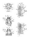
- FIG. 1 is a perspective view of a locking beam nut in accordance with one preferred embodiment of the invention.
- FIG. 2 is a top plan view of the locking beam nut of FIG. 1.
- FIG. 3 is an enlarged sectional view of one locking beam from the locking beam nut of FIG. 1, taken substantially in the direction of the arrows 3-3 in FIG. 1, the beam being depicted in its unflexed, radially-inward position.
- FIG. 4 is a side view of the locking beam nut of FIG. 1, with the locking beams positioned in their unflexed, radially-inward positions.
- FIG. 5 is an enlarged sectional view similar to FIG. 3, but showing the locking beam in its flexed, radially-outward position.
- FIG. 6 is a side view of the locking beam nut of FIG. 1, with the nut threadedly receiving a bolt such that the locking beams are flexed to their radially-outward positions.
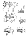
- FIG. 7 is an enlarged fragmentary side view of the slot between adjacent locking beams, showing the beams in their flexed, radially-outward positions.
- FIGS. 7A, 7B and 7C are enlarged, fragmentary cross-sectional views of the axial slot of FIG. 7, at the three locations indicated by the arrows A-A, B-B and C-C in FIG. 7, with the beams' flexed, radially-outward positions being shown in solid lines and unflexed, radially-inward positions being shown dotted lines.
- FIG. 8 is a perspective view of a second preferred embodiment of a lock nut in accordance with the invention, this lock nut including an unslotted sleeve having a stepped thickness similar to the stepped thickness of the locking beams of the first embodiment.
- FIG. 9 is a top plan view of the lock nut of FIG. 8.
- FIG. 10 is a sectional view of the lock nut of FIGS. 8 and 9, taken substantially in the direction of the arrows 10-10 in FIG. 9, showing the unslotted sleeve's stepped thickness.
- a locking beam nut 11 adapted to threadedly receive a bolt 13 and frictionally grip the bolt with a compressive force so as to secure the nut in place.
- the nut is in one piece and includes a rigid body 15 and a plurality (e.g., six) of flexible locking beams 17 projecting from one end of the rigid body. The beams are separated from each other by narrow, axially-oriented slots 19.
- the rigid body 15 includes a threaded bore 21, and the locking beams 17 cooperate to define a threaded bore 23 coaxial with the threaded bore of the rigid body.
- the beams deviate radially inwardly relative to the nut's longitudinal axis 25 such that the threaded bore they define has a diameter that is progressively smaller than the diameter of the threaded bore in the rigid body.
- the locking beams flex radially outwardly to accommodate the bolt, as shown in FIGS. 5 and 6.
- the resisting force causes the beams to frictionally engage the threads of the bolt, to secure the bolt within the nut and prevent vibration and the like from loosening the nut.
- the beams flex radially inwardly back to their unflexed positions (FIGS. 3 and 4).
- the locking beams 17 are made to flex at multiple locations along their lengths by configuring the beams to each have a radial thickness that steps downwardly with increasing distance from the rigid body 15. As best shown in FIGS. 3 and 5, each beam has a first uniform thickness T1 at a lower section 17a and a second, smaller uniform thickness T2 at an upper section 17b. A ledge 27 is thereby defined between the two sections.
- each beam When the bolt 13 is threaded into the nut 11, and the locking beams 17 flex radially outwardly to accommodate it, a substantial portion of the flexing of each beam occurs at the base or lower end of its lower section 17a and at the base or lower end of its upper section 17b. Flexing at multiple locations along the beam's length, in this fashion, enables a greater amount of total flex to be achieved without plastic deformation. Consequently, the nut will grip the bolt with a greater frictional force than could be achieved in the past with conventional beams having a more uniform thickness along their lengths. Flexing occurs in each beam section. Although only two such sections are depicted in this embodiment, it will be appreciated that a different plurality of sections could also be used.
- each locking beam 17 makes an angle X with the nut's longitudinal axis 25 and that the outer surface of the beam's upper section 17b makes an angle Y with the outer surface of the lower section 17a.
- the angles X and Y are substantially equal to each other, although it will be appreciated that this need not be the case.
- the plurality of locking beams 17 are replaced by a sleeve 29 that has been deformed into a slightly oval configuration.
- a threaded bore 31 defined by the interior surface of the sleeve has a minor dimension slightly less than the diameter of the threaded bore 21 in the rigid body 15.
- the sleeve is urged into a more circular shape, with its resistance to this flexing providing the frictional force that locks the bolt in place.
- the radial wall thickness of the sleeve steps downwardly with increasing distance from the rigid body. Consequently, the flexing of the wall occurs at multiple locations along the sleeve's length such that an increased total amount of elastic flexing can be achieved. This provides an improved, uniform locking on the bolt, even after multiple repeated uses.
- the axial slots 19 that separate the locking beams 17 from each other are configured to provide each beam with a relatively high strength, while at the same time ensuring that any rigid debris encrusted in the slot will not prevent the beams from returning to their unflexed, radially-inward positions (FIGS. 3 and 4) when the bolt 13 is removed.
- This slot configuration is depicted in detail in FIGS. 7 and 7A-7C. It will be noted that the slot is defined by confronting beam side walls 35 and 37 that include parallel portions 35a and 37a and diverging portions 35b and 37b.
- the diverging portions are located radially outwardly of the parallel portions, and the relative size of the diverging portions increases from a minimum at the base or lower ends of the beams, adjacent to the nut's rigid body 15, to a maximum at the remote or upper ends of the beams.
- FIGS. 7A-7C depict this flexing at the beams' remote tips, midpoints, and bases, respectively. It will be noted that at the beams' remote tips (FIG. 7A) the diverging portions 35b and 37b of the beam side walls 35 and 37, respectively, have a maximum size and are oriented substantially parallel with the respective radial deflection axes 39 and 41, respectively.
- any rigid debris located in this portion of the slot 19 will not prevent the resilient return of the beams from their flexed, radially outward positions (solid lines) to their unflexed, radially-inward positions (dotted lines), because the beams will simply slide along the debris.
- this angle of divergence is about 60 degrees.
- the parallel portions 35a and 37a of the beam side walls are about the same size as the diverging portions 35b and 37b, and the radial distance between the flexed, radially-outward position (solid lines) and unflexed, radially-inward position (dotted lines) is about half that for the remote ends (FIG. 7A).
- any rigid debris encrusted in this portion of the slot will not prevent a resilient return of the beams to their radially-inward positions when the bolt 13 is removed.
- the configuration for the axial slots 19 thus enables the locking beam nut 11 to function effectively in the presence of rigid debris encrusted in the slots, yet at the same time does not rob the beams of material considered important in providing the desired degree of strength. Resistance to flexing, and thus the frictional gripping force on the bolt 13, can therefore be maximized.
- the threaded bore 23 defined by the locking beams 17 includes axial or longitudinal recesses 43 in the regions of the slots 19. These recesses have depths roughly equal to the depth of the threads, so as to space the edges of each beam from the threads of the bolt 13. Further spacing the beam edges away from the bolt is the sizing of the beams' pitch radius to be slightly greater than (e.g., .002 inches) the bolt's pitch radius. The beam and bolt threads therefore are tangent with each other only at the midpoint of each beam. The recesses and the pitch radius difference combine to eliminate the need to separately remove any burrs formed during the creation of the slots. This also minimizes the possibility of galling the threads.
- the present invention provides an improved lock nut adapted for repeated use in locking onto a series of bolts, each time compressively gripping the bolt with substantially the same high compressive force.
- a resilient locking means that flexes at multiple locations along its length, whereby the total amount of elastic flexing can be maximized.
- the longitudinal slots separating adjacent locking beams are configured to enable repeated use of the lock nut despite the presence of rigid debris encrusted in the slots, while at the same time maximizing the strength of each beam in resisting the flexing and providing a maximum compressive gripping force on the bolt.
- the lock nut's threaded bore is longitudinally recessed in the region of each slot, to space the edges of each beam from the bolt and thereby prevent galling of the threads.
Landscapes
- Engineering & Computer Science (AREA)
- General Engineering & Computer Science (AREA)
- Mechanical Engineering (AREA)
- Dowels (AREA)
Applications Claiming Priority (1)
| Application Number | Priority Date | Filing Date | Title |
|---|---|---|---|
| US07/331,271 US4990043A (en) | 1989-03-30 | 1989-03-30 | Lock nut |
Publications (1)
| Publication Number | Publication Date |
|---|---|
| EP0460335A1 true EP0460335A1 (de) | 1991-12-11 |
Family
ID=23293280
Family Applications (1)
| Application Number | Title | Priority Date | Filing Date |
|---|---|---|---|
| EP90630115A Withdrawn EP0460335A1 (de) | 1989-03-30 | 1990-06-06 | Verriegelungsmutter |
Country Status (2)
| Country | Link |
|---|---|
| US (1) | US4990043A (de) |
| EP (1) | EP0460335A1 (de) |
Cited By (8)
| Publication number | Priority date | Publication date | Assignee | Title |
|---|---|---|---|---|
| EP0800878A1 (de) * | 1996-04-08 | 1997-10-15 | Illinois Tool Works Inc. | Verfahren zum Verformen einer Sicherungsmutter |
| EP0801236A1 (de) * | 1996-04-08 | 1997-10-15 | Illinois Tool Works Inc. | Gegenstand mit Gewinde |
| WO2001098011A1 (de) * | 2000-06-21 | 2001-12-27 | Erich Neumayer Gmbh & Co. Kg | Verfahren zur herstellung einer mutter, gewindebohrer zur durchführung des verfahrens und nach diesem verfahren hergestellte mutter |
| EP1201946A3 (de) * | 2000-10-25 | 2003-05-07 | NEDSCHROEF PLETTENBERG GmbH | Mutter mit einer Klemmsicherung |
| FR2884454A1 (fr) * | 2005-04-14 | 2006-10-20 | France Rayons Soc Par Actions | Ecrou frein pour rayons de bicyclettes et procede de montage desdits rayons |
| US9145923B2 (en) | 2013-07-03 | 2015-09-29 | General Electric Company | Load coupling for adjusting torsional natural frequency of a power train |
| US9518610B2 (en) | 2013-05-28 | 2016-12-13 | General Electric Company | Load coupling and method for adjusting torsional natural frequency of power train |
| CN111215289A (zh) * | 2020-03-04 | 2020-06-02 | 龙游讴凡纳米材料有限公司 | 一种包装机关键部件的金属表面纳米涂层装置 |
Families Citing this family (17)
| Publication number | Priority date | Publication date | Assignee | Title |
|---|---|---|---|---|
| US5499893A (en) * | 1993-12-29 | 1996-03-19 | Illinois Tool Works Inc. | Flexible lock nut and method of manufacturing |
| DE19532709A1 (de) * | 1994-09-15 | 1996-03-21 | Neumayer Erich Gmbh Co Kg | Mutter |
| USD412435S (en) * | 1997-07-16 | 1999-08-03 | Harley-Davidson Motor Company | Axle nut cover |
| US6832882B2 (en) | 2001-10-05 | 2004-12-21 | Illinois Tool Works Inc. | Fastener |
| USD469345S1 (en) | 2001-12-11 | 2003-01-28 | Trade Union International, Inc. | Bullet design wheel fastener with nut base |
| US7296382B2 (en) * | 2003-01-09 | 2007-11-20 | Pennsylvania Insert Corp. | Injection molded thermoplastic insert |
| US6808348B1 (en) * | 2003-04-09 | 2004-10-26 | Alcon Global Fasteners, Inc. | Lock nut member |
| USD555050S1 (en) * | 2005-12-16 | 2007-11-13 | Shimano Inc. | Front derailleur for a bicycle |
| US20090091084A1 (en) * | 2007-10-08 | 2009-04-09 | Seiff Stanley P | Card game |
| US20090116897A1 (en) * | 2007-11-02 | 2009-05-07 | Roger Svensson | Ball steering pin assembly for reduced wear and method therefor |
| USD581777S1 (en) * | 2008-02-05 | 2008-12-02 | Grand General Accessories Manufacturing | Tower-style lug nut cover |
| CN101608657B (zh) * | 2009-07-21 | 2011-08-03 | 北京市春立正达医疗器械股份有限公司 | 自锁螺母 |
| US11211749B2 (en) * | 2017-08-03 | 2021-12-28 | The Nielsen Company (Us), Llc | Plug retainer apparatus and related methods |
| DE102017009395A1 (de) * | 2017-10-10 | 2019-04-11 | Neumayer Tekfor Engineering Gmbh | Mutter |
| USD1015862S1 (en) * | 2018-05-04 | 2024-02-27 | W Star Incorporée | Vehicle wheel nut |
| CN111963559A (zh) * | 2020-08-28 | 2020-11-20 | 东风商用车有限公司 | 一种具有自防松功能的轴头大螺母 |
| DE212021000501U1 (de) * | 2021-03-26 | 2023-09-04 | Kone Corporation | Befestigungsanordnung, Pfosten, Zugangskontrollvorrichtung und Zielsteuerungsvorrichtung |
Citations (3)
| Publication number | Priority date | Publication date | Assignee | Title |
|---|---|---|---|---|
| US2381110A (en) * | 1942-07-11 | 1945-08-07 | Edward F Chandler | Lock nut |
| CH247303A (fr) * | 1945-06-29 | 1947-02-28 | Affolter Auguste | Ecrou de sûreté et procédé pour sa fabrication. |
| US4805288A (en) * | 1986-07-01 | 1989-02-21 | Rexnord Inc. | Method for making and using a locking beam nut |
Family Cites Families (8)
| Publication number | Priority date | Publication date | Assignee | Title |
|---|---|---|---|---|
| GB191016223A (en) * | 1910-07-07 | 1911-03-30 | Bayliss Jones And Bayliss Ltd | Improvements in, and in the Manufacture of, Lock-nuts. |
| US2290270A (en) * | 1938-09-16 | 1942-07-21 | Clare L Brackett | Self-binding nut |
| GB656348A (en) * | 1949-01-05 | 1951-08-22 | Brown Brothers Aircraft Ltd | Improvements in or relating to self-locking nuts |
| FR1111508A (fr) * | 1952-06-20 | 1956-03-01 | Perfectionnements aux pièces filetées | |
| US2897867A (en) * | 1957-05-06 | 1959-08-04 | Torre Joseph La | Lock nut having pivoting concave bearing end and inwardly deformed tip to effectuate uniformly stressed threads |
| US3507313A (en) * | 1968-10-08 | 1970-04-21 | Standard Pressed Steel Co | Locknut |
| US3702628A (en) * | 1970-11-27 | 1972-11-14 | Tridair Industries | Lock nut member |
| GB2192249B (en) * | 1986-07-01 | 1990-11-28 | Rexnord Inc | Locking beam nut |
-
1989
- 1989-03-30 US US07/331,271 patent/US4990043A/en not_active Expired - Lifetime
-
1990
- 1990-06-06 EP EP90630115A patent/EP0460335A1/de not_active Withdrawn
Patent Citations (3)
| Publication number | Priority date | Publication date | Assignee | Title |
|---|---|---|---|---|
| US2381110A (en) * | 1942-07-11 | 1945-08-07 | Edward F Chandler | Lock nut |
| CH247303A (fr) * | 1945-06-29 | 1947-02-28 | Affolter Auguste | Ecrou de sûreté et procédé pour sa fabrication. |
| US4805288A (en) * | 1986-07-01 | 1989-02-21 | Rexnord Inc. | Method for making and using a locking beam nut |
Cited By (9)
| Publication number | Priority date | Publication date | Assignee | Title |
|---|---|---|---|---|
| EP0800878A1 (de) * | 1996-04-08 | 1997-10-15 | Illinois Tool Works Inc. | Verfahren zum Verformen einer Sicherungsmutter |
| EP0801236A1 (de) * | 1996-04-08 | 1997-10-15 | Illinois Tool Works Inc. | Gegenstand mit Gewinde |
| WO2001098011A1 (de) * | 2000-06-21 | 2001-12-27 | Erich Neumayer Gmbh & Co. Kg | Verfahren zur herstellung einer mutter, gewindebohrer zur durchführung des verfahrens und nach diesem verfahren hergestellte mutter |
| US6840866B2 (en) | 2000-06-21 | 2005-01-11 | Erich Neumayer Gmbh & Co. Kg | Method for producing a nut, screw tap for the performance of the method, and a nut produced according to the method |
| EP1201946A3 (de) * | 2000-10-25 | 2003-05-07 | NEDSCHROEF PLETTENBERG GmbH | Mutter mit einer Klemmsicherung |
| FR2884454A1 (fr) * | 2005-04-14 | 2006-10-20 | France Rayons Soc Par Actions | Ecrou frein pour rayons de bicyclettes et procede de montage desdits rayons |
| US9518610B2 (en) | 2013-05-28 | 2016-12-13 | General Electric Company | Load coupling and method for adjusting torsional natural frequency of power train |
| US9145923B2 (en) | 2013-07-03 | 2015-09-29 | General Electric Company | Load coupling for adjusting torsional natural frequency of a power train |
| CN111215289A (zh) * | 2020-03-04 | 2020-06-02 | 龙游讴凡纳米材料有限公司 | 一种包装机关键部件的金属表面纳米涂层装置 |
Also Published As
| Publication number | Publication date |
|---|---|
| US4990043A (en) | 1991-02-05 |
Similar Documents
| Publication | Publication Date | Title |
|---|---|---|
| US4990043A (en) | Lock nut | |
| CA1289784C (en) | Knurled cup-point set screw | |
| KR100965443B1 (ko) | 스로 어웨이 팁 | |
| EP0529134B1 (de) | Sichernde Schraube | |
| US4327465A (en) | Handle for tool having a tang | |
| JP4065334B2 (ja) | 2つの工具部品を連結する工具継手と連結方法 | |
| US4718802A (en) | Sawtooth-profile nail | |
| DE602004002123T2 (de) | Halteelement | |
| JPH0817783B2 (ja) | 生体適合性保持ピンおよびそれを含む補綴具 | |
| CA2189206C (en) | Fixing device | |
| US5868537A (en) | Sponge head retainer pin | |
| HU189838B (en) | Plastic material strain pin | |
| US4274460A (en) | Panel fastener joint | |
| EP0828460A1 (de) | Zahnimplantat zur schraubmontage mit verringerter reibung | |
| KR19990035735A (ko) | 작업 공구 | |
| DE102018106558B4 (de) | Von vorn geladener, seitlich aktivierter, modularer bohrer und schneideinsatz | |
| US5772551A (en) | Dual flexible bite connector | |
| KR102498184B1 (ko) | 커플링 나사 고정을 위한 고정 부재를 가진 절삭 공구 및 절삭 공구 몸체 | |
| JP4255231B2 (ja) | ブラインドリベット | |
| US3340920A (en) | Prevailing torque locknut | |
| KR20020026796A (ko) | 나사부재 | |
| US4805288A (en) | Method for making and using a locking beam nut | |
| JPH0893742A (ja) | ナット | |
| EP0611321B1 (de) | Schraube für ein spielzeugkonstruktionsset | |
| EP0444795B1 (de) | Befestigungsmittel |
Legal Events
| Date | Code | Title | Description |
|---|---|---|---|
| PUAI | Public reference made under article 153(3) epc to a published international application that has entered the european phase |
Free format text: ORIGINAL CODE: 0009012 |
|
| AK | Designated contracting states |
Kind code of ref document: A1 Designated state(s): BE DE ES FR GB IT SE |
|
| STAA | Information on the status of an ep patent application or granted ep patent |
Free format text: STATUS: THE APPLICATION IS DEEMED TO BE WITHDRAWN |
|
| 18D | Application deemed to be withdrawn |
Effective date: 19920612 |