EP0460395B1 - Dispositif de coupe pour une enrouleuse de bande - Google Patents
Dispositif de coupe pour une enrouleuse de bande Download PDFInfo
- Publication number
- EP0460395B1 EP0460395B1 EP91106933A EP91106933A EP0460395B1 EP 0460395 B1 EP0460395 B1 EP 0460395B1 EP 91106933 A EP91106933 A EP 91106933A EP 91106933 A EP91106933 A EP 91106933A EP 0460395 B1 EP0460395 B1 EP 0460395B1
- Authority
- EP
- European Patent Office
- Prior art keywords
- cutting device
- cutting
- cutting blade
- web
- arms
- Prior art date
- Legal status (The legal status is an assumption and is not a legal conclusion. Google has not performed a legal analysis and makes no representation as to the accuracy of the status listed.)
- Expired - Lifetime
Links
Images


Classifications
-
- B—PERFORMING OPERATIONS; TRANSPORTING
- B65—CONVEYING; PACKING; STORING; HANDLING THIN OR FILAMENTARY MATERIAL
- B65H—HANDLING THIN OR FILAMENTARY MATERIAL, e.g. SHEETS, WEBS, CABLES
- B65H18/00—Winding webs
- B65H18/08—Web-winding mechanisms
- B65H18/14—Mechanisms in which power is applied to web roll, e.g. to effect continuous advancement of web
- B65H18/20—Mechanisms in which power is applied to web roll, e.g. to effect continuous advancement of web the web roll being supported on two parallel rollers at least one of which is driven
-
- B—PERFORMING OPERATIONS; TRANSPORTING
- B65—CONVEYING; PACKING; STORING; HANDLING THIN OR FILAMENTARY MATERIAL
- B65H—HANDLING THIN OR FILAMENTARY MATERIAL, e.g. SHEETS, WEBS, CABLES
- B65H19/00—Changing the web roll
- B65H19/22—Changing the web roll in winding mechanisms or in connection with winding operations
- B65H19/26—Cutting-off the web running to the wound web roll
-
- B—PERFORMING OPERATIONS; TRANSPORTING
- B65—CONVEYING; PACKING; STORING; HANDLING THIN OR FILAMENTARY MATERIAL
- B65H—HANDLING THIN OR FILAMENTARY MATERIAL, e.g. SHEETS, WEBS, CABLES
- B65H2301/00—Handling processes for sheets or webs
- B65H2301/40—Type of handling process
- B65H2301/41—Winding, unwinding
- B65H2301/417—Handling or changing web rolls
- B65H2301/4187—Relative movement of core or web roll in respect of mandrel
- B65H2301/4189—Cutting
- B65H2301/41891—Cutting knife located between two winding rollers
-
- B—PERFORMING OPERATIONS; TRANSPORTING
- B65—CONVEYING; PACKING; STORING; HANDLING THIN OR FILAMENTARY MATERIAL
- B65H—HANDLING THIN OR FILAMENTARY MATERIAL, e.g. SHEETS, WEBS, CABLES
- B65H2301/00—Handling processes for sheets or webs
- B65H2301/40—Type of handling process
- B65H2301/41—Winding, unwinding
- B65H2301/417—Handling or changing web rolls
- B65H2301/4187—Relative movement of core or web roll in respect of mandrel
- B65H2301/4189—Cutting
- B65H2301/41894—Cutting knife moving on circular or acuate path, e.g. pivoting around winding roller
Definitions
- the invention concerns a cutting device for a web winder, said device comprising a frame construction and a cutting blade, by means of which cutting blade the web in the reel formed on support of the carrier drums can be cut off before new winding is started.
- This prior-art carrier-drum winder comprises a rear and a front carrier drum, web cutting means, pushing means for the transfer of a complete reel from the carrier drums, and means for feeding a new reeling spool.
- the cutting means and the feeding means are operationally connected with the pushing means so as to be displaced to their operation positions by means of a common support arm.
- the carrier-drum winder includes a backup holder, which is pushed to project from between the carrier drums and which holds the web against the rear carrier drum.
- the cutting means include a member for cutting off the web by means of a stroke-like movement of the cutting blade, said movement being directed at the area of the tip of the backup holder, towards the web portion placed between, and held tight by, said tip and the pushing means.
- a cutting device for a web winder comprising a frame construction and a cutting blade, by means of which cutting blade the web in the reel formed on support of the carrier drums can be cut off before new winding is started, the cutting blade being fitted to move along a curved path of movement where said curved movement of rotation has been chosen so that the centre of rotation of the cutting blade is separate from the centre of rotation of the carrier drum to the effect that the position of the cutting blade in the lower position is substantially more distant from the carrier drum than in the upper position.
- the object of the present invention is to provide an improvement over the prior-art web cutting devices.
- a further object of the invention is to provide a cutting device which can be attached to the frame of any carrier-drum winder whatsoever.
- the cutting device in accordance with the invention, a number of remarkable advantages are obtained.
- the cutting device can be attached to the frame of any carrier-drum winder whatsoever.
- the cutting blade of the cutting device can be passed into the gap between the carrier rolls either from below, from the front, from the rear, or from above.
- auxiliary devices are, for example, a blow device for holding the end of the cut-off web, a web holding device, and a threading member, etc.
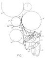
- Figure 1 is a side view of a preferred embodiment of a cutting device in accordance with the invention.
- Figure 2 is a side view of a second preferred embodiment of a cutting device in accordance with the invention.
- Figure 3 is a side view of a third preferred embodiment of a cutting device in accordance with the invention.
- Figure 4 is a side view of a fourth preferred embodiment of a cutting device in accordance with the invention.
- Figure 5 is a side view of a fifth preferred embodiment of a cutting device in accordance with the invention.
- the cutting device in accordance with the invention is denoted generally with the reference numeral 10.
- the cutting device 10 comprises a frame 11, a synchronization tube 12, first arms 13 that are fitted pivotally, second arms 14 that are fitted pivotally, a cutting-blade frame 15 and a cutting blade 16, as well as a actuator 17.
- the frame tube which is a part of the frame 11, is denoted with the reference numeral 11a.
- the frame tube 11a passes in the transverse direction through the carrier-drum winder to the other side.
- the cutting device 10 is applied in a carrier-drum winder which comprises a conventional carrier drum 18 as well as a carrier drum 19 consisting of a roll 19a and of another roll, not shown, and of a belt 19b.
- the reel is denoted with the reference numeral 20.
- the cutting blade 16 of the cutting device 10 is passed into the gap between the carrier drums 18 and 19 from below.
- the cutting device 10 is attached to the frame construction.
- the cutting device 10 shown in Fig. 1 operates as follows.
- the movement of the actuator 17, e.g. a hydraulic cylinder, acts upon the first arms 13, which are linked with the second arms 14.
- the pivoting movement of the arms 13 is synchronized by means of the synchronization tube 12.
- the frame 15 of the cutting blade 16 is linked with the second arms 14.
- the movement of the actuator 17 is transferred to the frame 15 by the intermediate of the arms 13 and 14, whereby the frame 15 of the cutting blade 16 and the blade 16, which is attached to said frame, obtain a curved movement of rotation in relation to the face of the carrier drum 18.
- This curved movement of rotation has been chosen so that the centre of rotation of the cutting blade 16 is separate from the centre of rotation of the carrier drum 18.
- the centre of rotation of the blade 16 can be chosen fully freely, provided that the centre of rotation of the blade 16 does not coincide with the centre of rotation of the carrier drum 18.
- the dashed lines indicate the lower position of the cutting blade 16 and, in a corresponding way, the full lines indicate the upper position. From Fig. 1, it comes out clearly that in the lower position the cutting blade 16 is placed at a certain distance from the face of the carrier drum 18, and in the upper position the cutting blade 16 is placed very close to the face of the carrier drum 18.
- the cutting proper of the web takes place either merely because the blade 16 is sharp enough to pass through the web that is placed tensioned on the reel 20.
- the cutting of the web placed on the reel 20 may also take place so that the reel 20 is pushed by means of a pushing device in itself known, in which case the tensioned web forms a sufficient angle in relation to the cutting blade 16, whereby the web is cut off.
- FIG. 2 illustrates the passing of the cutting device 10 in accordance with the invention into the gap between the carrier drums 18 and 19 from the side, i.e., in the present case, from the rear.
- the carrier-drum winder comprises conventional carrier drums 18 and 19.
- the passing of the cutting device 10 takes place similarly to Fig. 1, from below.
- the carrier-drum winder is composed of conventional carrier drums 18 and 19. Further, in this embodiment, the cutting device 10 is provided with a blow device 21.
- the embodiment shown in Fig. 4 is in the other respects similar to the embodiment shown in Fig. 1, but the cutting device 10 shown in Fig. 4 is provided both with a blow device 21 and with a web holder 22.
- Fig. 5 shows a embodiment which is in the other respects similar to the embodiment shown in Fig. 1 except that, in the embodiment shown in Fig. 5, the cutting device 10 is provided both with a blow device 21 and with a web threading member 23.
- the cutting device 10 in accordance with the invention operates during normal winding and during reel exchange as follows.
- the blade 16 has been run down so that there is a sufficient space underneath the carrier drum 18.
- the threading member 23 is placed underneath the carrier drum 18, and the cutting blade 16 of the cutting device 10 has been run to its extreme upper position.
- the cutting blade 16 has moved to its extreme upper position through the gap between the carrier drums 18 and 19, in which case it is possible to carry out conventional cutting-off of the web.
- the cut-off end of the web can be held in its position, e.g., by means of a blow device 21 shown in Figs. 3 and 4.
- the cutting blade 16 is moved slightly down to permit fitting of a new spool into the gap between the carrier drums 18 and 19.
- the reel exchange constitutes prior art, it will not be described in further detail in connection with the invention disclosed in the present application.
- the cutting device 10 in accordance with the invention permits a very smooth and fluent exchange of reel.
Landscapes
- Replacement Of Web Rolls (AREA)
Claims (9)
- Dispositif de coupe pour une enrouleuse de bande continue, ce dispositif (10) comprenant une structure de châssis (11) et une lame de coupe (16) au moyen de laquelle lame de coupe (16), la bande continue dans la bobine (20) formée sur le support des tambours porteurs (18, 19) peut être coupée avant de commencer un réenroulement, la lame de coupe (16) étant apte à se déplacer le long d'une trajectoire courbe lorsque l'on a choisi un mouvement courbe de rotation de façon à séparer le centre de rotation de la lame de coupe (16) du centre de rotation du tambour porteur (18), de sorte que dans la position inférieure, la position de la lame de coupe (16) est sensiblement plus éloignée du tambour porteur (18) que dans la position supérieure,
caractérisé en ce que
le dispositif de coupe (10) comprend un organe d'actionnement (17) et des éléments de transfert de puissance (13, 14) qui consistent en des premiers bras (13) et des seconds bras (14), ces bras étant reliés entre eux de façon pivotante, en ce que les mouvements de rotation des premiers bras (13) sont synchronisés au moyen d'un tube de synchronisation (12) et en ce que les éléments de transfert de puissance (13, 14) sont raccordés de façon opérante à la lame de coupe (16) du dispositif de coupe (10) de sorte que le mouvement de l'organe d'actionnement (17) est apte à être transmis par l'intermédiaire des éléments de transfert de puissance (13, 14) sur la lame de coupe (16). - Dispositif de coupe selon la revendication 1,
caractérisé en ce que
les seconds bras (14) des éléments de transfert de puissance (13, 14) sont raccordés à la structure de châssis (15) de la lame de coupe (16) de façon pivotante. - Dispositif de coupe selon l'une quelconque des revendications 1 et 2,
caractérisé en ce que
le dispositif de coupe (10) est raccordé à un dispositif de soufflage (21) pour retenir l'extrémité coupée de la bande continue. - Dispositif de coupe selon l'une quelconque des revendications 1 et 2,
caractérisé en ce que
le dispositif de coupe (10) est raccordé à un dispositif de support de bande continue (22). - Dispositif de coupe selon l'une quelconque des revendications 1 à 4,
caractérisé en ce que
le dispositif de coupe (10) est raccordé à un élément d'enfilement (23) pour la nouvelle bande continue. - Dispositif de coupe selon l'une quelconque des revendications 1 à 5,
caractérisé en ce que
la lame de coupe (16) du dispositif de coupe (10) est apte à se déplacer sur une trajectoire de mouvement courbe jusque dans l'espace entre les tambours porteurs (18, 19) par le dessous. - Dispositif de coupe selon l'une quelconque des revendications 1 à 5,
caractérisé en ce que
la lame de coupe (16) du dispositif de coupe (10) est apte à se déplacer le long d'une trajectoire de mouvement courbe jusque dans l'espace entre les tambours porteurs (18, 19) par le côté. - Dispositif de coupe selon l'une quelconque des revendications 1 à 5,
caractérisé en ce que
la lame de coupe (16) du dispositif de coupe (10) est apte à se déplacer le long de la trajectoire de mouvement courbe jusque dans l'espace entre les tambours porteurs (18, 19) par le dessus. - Dispositif de coupe selon l'une quelconque des revendications 1 à 8,
caractérisé en ce que
l'organe d'actionnement (17) est un vérin hydraulique, en ce que les premiers bras (13) sont des bras articulés qui sont montés de façon pivotante et en ce que les seconds bras pivotants (14) sont des bras articulés qui sont montés de façon pivotante.
Applications Claiming Priority (2)
| Application Number | Priority Date | Filing Date | Title |
|---|---|---|---|
| FI902890 | 1990-06-08 | ||
| FI902890A FI94514C (fi) | 1990-06-08 | 1990-06-08 | Katkaisulaite rainan rullauslaitetta varten |
Publications (2)
| Publication Number | Publication Date |
|---|---|
| EP0460395A1 EP0460395A1 (fr) | 1991-12-11 |
| EP0460395B1 true EP0460395B1 (fr) | 1995-07-26 |
Family
ID=8530601
Family Applications (1)
| Application Number | Title | Priority Date | Filing Date |
|---|---|---|---|
| EP91106933A Expired - Lifetime EP0460395B1 (fr) | 1990-06-08 | 1991-04-29 | Dispositif de coupe pour une enrouleuse de bande |
Country Status (5)
| Country | Link |
|---|---|
| EP (1) | EP0460395B1 (fr) |
| JP (1) | JP2515633B2 (fr) |
| CA (1) | CA2044066C (fr) |
| DE (1) | DE69111517T2 (fr) |
| FI (1) | FI94514C (fr) |
Families Citing this family (3)
| Publication number | Priority date | Publication date | Assignee | Title |
|---|---|---|---|---|
| FI92995C (fi) * | 1993-06-30 | 1995-02-10 | Valmet Paper Machinery Inc | Kantotelarullain |
| FI100324B (fi) * | 1994-12-13 | 1997-11-14 | Valmet Paper Machinery Inc | Menetelmä ja sovitelma radan katkaisemiseksi |
| DE19901112B4 (de) * | 1999-01-14 | 2004-04-01 | Voith Paper Patent Gmbh | Rollenwickelvorrichtung |
Family Cites Families (5)
| Publication number | Priority date | Publication date | Assignee | Title |
|---|---|---|---|---|
| DE2301193C2 (de) * | 1973-01-11 | 1985-09-19 | Maschinenfabrik Stahlkontor Weser Lenze KG, 3258 Aerzen | Vorrichtung zum Wickelrollenwechsel und zum Quertrennen von schnellaufenden Bahnen |
| FI53560C (fi) * | 1976-03-12 | 1978-06-12 | Ahlstroem Oy | Foerfarande och anordning foer upprullning av materialbanor |
| CA1201055A (fr) * | 1983-02-04 | 1986-02-25 | Louis J. Bagnato | Massicot |
| JPS62255342A (ja) * | 1985-11-28 | 1987-11-07 | Japan Tobacco Inc | 巻取ウエブ接続準備装置 |
| FR2637276B1 (fr) * | 1988-10-05 | 1991-08-09 | Monomatic Sa | Dispositif de raccordement et de coupe d'une bande, en fonctionnement, sur un nouveau mandrin d'un enrouleur en continu |
-
1990
- 1990-06-08 FI FI902890A patent/FI94514C/fi not_active IP Right Cessation
-
1991
- 1991-04-29 EP EP91106933A patent/EP0460395B1/fr not_active Expired - Lifetime
- 1991-04-29 DE DE69111517T patent/DE69111517T2/de not_active Expired - Fee Related
- 1991-06-03 JP JP3157362A patent/JP2515633B2/ja not_active Expired - Fee Related
- 1991-06-07 CA CA002044066A patent/CA2044066C/fr not_active Expired - Fee Related
Also Published As
| Publication number | Publication date |
|---|---|
| FI94514B (fi) | 1995-06-15 |
| JPH04226247A (ja) | 1992-08-14 |
| CA2044066C (fr) | 1994-11-08 |
| FI902890A0 (fi) | 1990-06-08 |
| CA2044066A1 (fr) | 1991-12-09 |
| DE69111517D1 (de) | 1995-08-31 |
| DE69111517T2 (de) | 1996-01-11 |
| FI902890A7 (fi) | 1991-12-09 |
| JP2515633B2 (ja) | 1996-07-10 |
| EP0460395A1 (fr) | 1991-12-11 |
| FI94514C (fi) | 1995-09-25 |
Similar Documents
| Publication | Publication Date | Title |
|---|---|---|
| US5975457A (en) | Web feeding systems | |
| KR910009544A (ko) | 웨브 재료 연속 권취기 | |
| KR20010086203A (ko) | 연속 와인더 | |
| US6386477B1 (en) | Station for continuous unwinding of a material web | |
| US4979689A (en) | Method and apparatus for winding a web | |
| CA2092462A1 (fr) | Bobineuse pour le bobinage d'une bande, en particulier une bande de papier | |
| CA2273370A1 (fr) | Machine de bobinage et de deroulement pour obtenir des bobines de matiere fibreuse a large diametre | |
| FR2496615A1 (fr) | Procede et dispositif pour remplacer une premiere bobine vide de materiau en bande, par une seconde bobine pleine | |
| US5692698A (en) | Web feeding and transition assembly | |
| EP1135316B1 (fr) | Enroulement et methode d'enroulement d'une bande de papier | |
| US5505403A (en) | Drum winder and method for drum winding a web | |
| EP0460395B1 (fr) | Dispositif de coupe pour une enrouleuse de bande | |
| AU2524199A (en) | Apparatus and method for continuously reeling a web material | |
| CA2039876A1 (fr) | Bobineuse servant a l'enroulement d'une trame continue | |
| US6644586B2 (en) | Winding device | |
| US6729573B2 (en) | Roll changer and process for automatic roll change during stoppage | |
| GB2162157A (en) | Web winder | |
| BR9908860A (pt) | Bobinador numa máquina de papel para manufaturar um rolo de papel contìnuo | |
| US6322020B1 (en) | Reel winding device and process having cutter holder movable in accordance with a wound roll diameter | |
| US5584445A (en) | Center wind assist mechanism in secondary position | |
| EP0684338A3 (fr) | Porte-lame. | |
| GB2286181B (en) | Method and machine for unwinding and splicing rolls of material in strip form | |
| SE9100633D0 (sv) | Wickelmaschine zum aufwickeln einer laufenden bahn | |
| CA2046351A1 (fr) | Dispositif pour fixer une bande adhesive sur l'extremite d'un rouleau de papier | |
| EP1172320B1 (fr) | Dispositif pour raccorder la fin d'un rouleau de papier au début d'un nouveau rouleau de papier |
Legal Events
| Date | Code | Title | Description |
|---|---|---|---|
| PUAI | Public reference made under article 153(3) epc to a published international application that has entered the european phase |
Free format text: ORIGINAL CODE: 0009012 |
|
| AK | Designated contracting states |
Kind code of ref document: A1 Designated state(s): DE FR GB SE |
|
| 17P | Request for examination filed |
Effective date: 19920219 |
|
| 17Q | First examination report despatched |
Effective date: 19931124 |
|
| GRAA | (expected) grant |
Free format text: ORIGINAL CODE: 0009210 |
|
| AK | Designated contracting states |
Kind code of ref document: B1 Designated state(s): DE FR GB SE |
|
| REF | Corresponds to: |
Ref document number: 69111517 Country of ref document: DE Date of ref document: 19950831 |
|
| ET | Fr: translation filed | ||
| PLBE | No opposition filed within time limit |
Free format text: ORIGINAL CODE: 0009261 |
|
| STAA | Information on the status of an ep patent application or granted ep patent |
Free format text: STATUS: NO OPPOSITION FILED WITHIN TIME LIMIT |
|
| 26N | No opposition filed | ||
| REG | Reference to a national code |
Ref country code: GB Ref legal event code: IF02 |
|
| PGFP | Annual fee paid to national office [announced via postgrant information from national office to epo] |
Ref country code: GB Payment date: 20040331 Year of fee payment: 14 |
|
| PGFP | Annual fee paid to national office [announced via postgrant information from national office to epo] |
Ref country code: SE Payment date: 20040402 Year of fee payment: 14 |
|
| PGFP | Annual fee paid to national office [announced via postgrant information from national office to epo] |
Ref country code: DE Payment date: 20040408 Year of fee payment: 14 |
|
| PGFP | Annual fee paid to national office [announced via postgrant information from national office to epo] |
Ref country code: FR Payment date: 20040415 Year of fee payment: 14 |
|
| PG25 | Lapsed in a contracting state [announced via postgrant information from national office to epo] |
Ref country code: GB Free format text: LAPSE BECAUSE OF NON-PAYMENT OF DUE FEES Effective date: 20050429 |
|
| PG25 | Lapsed in a contracting state [announced via postgrant information from national office to epo] |
Ref country code: SE Free format text: LAPSE BECAUSE OF NON-PAYMENT OF DUE FEES Effective date: 20050430 |
|
| PG25 | Lapsed in a contracting state [announced via postgrant information from national office to epo] |
Ref country code: DE Free format text: LAPSE BECAUSE OF NON-PAYMENT OF DUE FEES Effective date: 20051101 |
|
| EUG | Se: european patent has lapsed | ||
| GBPC | Gb: european patent ceased through non-payment of renewal fee |
Effective date: 20050429 |
|
| PG25 | Lapsed in a contracting state [announced via postgrant information from national office to epo] |
Ref country code: FR Free format text: LAPSE BECAUSE OF NON-PAYMENT OF DUE FEES Effective date: 20051230 |
|
| REG | Reference to a national code |
Ref country code: FR Ref legal event code: ST Effective date: 20051230 |