EP0460464A2 - Véhicule comportant un ventilateur pour le système de refroidissement du moteur thermique ainsi qu'une servo-direction du type à centre ouvert - Google Patents
Véhicule comportant un ventilateur pour le système de refroidissement du moteur thermique ainsi qu'une servo-direction du type à centre ouvert Download PDFInfo
- Publication number
- EP0460464A2 EP0460464A2 EP91108428A EP91108428A EP0460464A2 EP 0460464 A2 EP0460464 A2 EP 0460464A2 EP 91108428 A EP91108428 A EP 91108428A EP 91108428 A EP91108428 A EP 91108428A EP 0460464 A2 EP0460464 A2 EP 0460464A2
- Authority
- EP
- European Patent Office
- Prior art keywords
- hydraulic
- motor
- steering device
- power steering
- pump
- Prior art date
- Legal status (The legal status is an assumption and is not a legal conclusion. Google has not performed a legal analysis and makes no representation as to the accuracy of the status listed.)
- Withdrawn
Links
Images
Classifications
-
- B—PERFORMING OPERATIONS; TRANSPORTING
- B62—LAND VEHICLES FOR TRAVELLING OTHERWISE THAN ON RAILS
- B62D—MOTOR VEHICLES; TRAILERS
- B62D5/00—Power-assisted or power-driven steering
- B62D5/06—Power-assisted or power-driven steering fluid, i.e. using a pressurised fluid for most or all the force required for steering a vehicle
- B62D5/07—Supply of pressurised fluid for steering also supplying other consumers ; control thereof
-
- F—MECHANICAL ENGINEERING; LIGHTING; HEATING; WEAPONS; BLASTING
- F01—MACHINES OR ENGINES IN GENERAL; ENGINE PLANTS IN GENERAL; STEAM ENGINES
- F01P—COOLING OF MACHINES OR ENGINES IN GENERAL; COOLING OF INTERNAL-COMBUSTION ENGINES
- F01P5/00—Pumping cooling-air or liquid coolants
- F01P5/02—Pumping cooling-air; Arrangements of cooling-air pumps, e.g. fans or blowers
- F01P5/04—Pump-driving arrangements
-
- F—MECHANICAL ENGINEERING; LIGHTING; HEATING; WEAPONS; BLASTING
- F01—MACHINES OR ENGINES IN GENERAL; ENGINE PLANTS IN GENERAL; STEAM ENGINES
- F01P—COOLING OF MACHINES OR ENGINES IN GENERAL; COOLING OF INTERNAL-COMBUSTION ENGINES
- F01P7/00—Controlling of coolant flow
- F01P7/02—Controlling of coolant flow the coolant being cooling-air
- F01P7/04—Controlling of coolant flow the coolant being cooling-air by varying pump speed, e.g. by changing pump-drive gear ratio
- F01P7/044—Controlling of coolant flow the coolant being cooling-air by varying pump speed, e.g. by changing pump-drive gear ratio using hydraulic drives
Definitions
- the invention relates to a motor vehicle with a fan for the cooling system of its internal combustion engine and with a hydraulic power steering device of the flow type of the type mentioned in the preamble of claim 1, as is generally known.
- the i. a. Hydraulic pump driven by the internal combustion engine promotes a constant flow of hydraulic oil which, when the steering is not actuated - is passed by the hydraulic actuators of the power steering device - essentially without pressure - and that the hydraulic actuators only when the steering is actuated via a steering wheel or its steering column coupled hydraulic steering valve depending on the direction of the steering lock in one or the other direction with a hydraulic pressure that builds up in the process.
- An essential advantage of such servo steering devices of the flow type which can be operated with a comparatively low pressure level is that, in contrast to servo steering devices of the storage type which operate with comparatively high system pressures no complex and expensive high-pressure-tight components are required, especially no high-pressure-tight steering valves.
- Servo steering devices of the flow type require more powerful hydraulic pumps than steering devices of the storage type, because they each have to spontaneously meet the requirements imposed by the servo steering device.
- this greater effort is negligible and negligible in view of the fact that, on the one hand, no pressure accumulator and, on the other hand, no high-pressure-tight components are required for the hydraulic circuit.
- the fan is driven by two hydraulic motors arranged on the same fan axis and designed as a tandem motor, by one of the internal combustion engines driven hydraulic pump are fed with the required hydraulic oil, with only one of the two hydraulic motors being used for the fan drive in the lower speed range of the internal combustion engine, while the other one is either uncoupled or rotates at idle.
- the system pressure of the hydraulic system is comparatively high and is limited to approximately 200 bar by an adjustable throttle switched into the suction line of the hydraulic pump.
- the invention has for its object to provide a well adaptable to tight space conditions, powerful, yet simple and inexpensive fan system for a motor vehicle with a hydraulic power steering device of the flow type of the type mentioned in the preamble of claim 1.
- the fan of the cooling system has, in a manner known per se, a hydraulic fan drive with a hydraulic motor, which, in contrast to the prior art, is not fed by its own hydraulic pump, but by the hydraulic pump of the hydraulic servo steering device, which already exists anyway by skillful design of the hydraulic circuit, the hydraulic motor of the fan is advantageously supplied with a hydraulic oil flow proportional to the pump speed, while the hydraulic servo steering device is supplied with a constant hydraulic oil flow in the usual and necessary manner.
- the arrangement according to the invention is characterized by its space-saving and cost-effective concept, which leads to better use of the hydraulic power already installed for the hydraulic power steering device and has the advantage of having a comparatively low system pressure of, for. B. to be operated up to 100 bar.
- a comparatively low operating pressure also enables the use of conventional, inexpensive components, since the comparatively low system pressure places significantly lower demands on the dimensional accuracy and the tightness of these components.
- Conventional gear pumps such as those that are mass-produced for motor vehicles as lubricating oil pumps, can thus advantageously be used for the hydraulic motor.
- the steering valve of the hydraulic power steering system is not subject to any stringent requirements either.
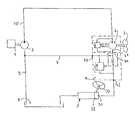
- the single figure of the drawing shows a simplified and schematic representation of the hydraulic circuit of a motor vehicle according to the invention.
- An internal combustion engine 1 drives a hydraulic pump 2, preferably a vane pump, which draws hydraulic oil from a reservoir 8 via a suction line 9 and via a Pressure line 10 feeds the hydraulic circuit connected downstream.
- a hydraulic pump 2 preferably a vane pump, which draws hydraulic oil from a reservoir 8 via a suction line 9 and via a Pressure line 10 feeds the hydraulic circuit connected downstream.
- the hydraulic circuit contains two hydraulic consumers connected to one another in series, namely a hydraulic motor 6 driving the fan 5 of the cooling system of the internal combustion engine 1 and the hydraulic power steering device 3 of the vehicle, i. H. more precisely, their hydraulic control and actuators.
- the hydraulic power steering device is designed as usual, i. H. it contains a hydraulic steering valve coupled to the steering wheel 33, which is indicated by 32, and one or more hydraulic actuators which are operatively connected to the steering linkage or the steerable wheels of the motor vehicle and which are controlled by the steering valve 32 when the steering wheel 33 is actuated by hydraulic oil supplied to the hydraulic pump 2 can be applied.
- a known hydraulic flow and quantity controller 4 is arranged, the input 41 of which is connected to the output 61 of the hydraulic motor 6 connected to the hydraulic pump 2 and the output 42 of which is connected to the input 31 of the hydraulic Servo steering device 3 or its steering valve 32 is connected.
- the part of the hydraulic oil flow conveyed by the hydraulic pump 2 which exceeds the constant hydraulic oil flow for the power steering device 3 is discharged via an outlet 43 of the flow and quantity regulator 4 and fed back to the hydraulic pump 2 or its suction chamber or suction connection via a pressure line 7.
- a hydraulic pump 2 and flow or quantity controller 4 preferably only slightly modified standard corresponding components of conventional hydraulic power steering devices of the flow type are used. These servo steering devices are usually supplied with hydraulic oil by a hydraulic pump designed as a vane pump with a current or quantity regulator flanged directly to the pump.
- such a standard vane pump without quantity regulator is used in an advantageous manner - for which purpose the vane pump as standard can be modified slightly in terms of construction - while the current or quantity regulator structurally separate from the vane pump is hydraulically separated between the hydraulic motor 6 and the hydraulic servo -Steering device is arranged.
- the flow or quantity controller 4 can advantageously be combined with the hydraulic motor 6 to form a structural unit.
Landscapes
- Engineering & Computer Science (AREA)
- Chemical & Material Sciences (AREA)
- Combustion & Propulsion (AREA)
- Mechanical Engineering (AREA)
- General Engineering & Computer Science (AREA)
- Transportation (AREA)
- Power Steering Mechanism (AREA)
Applications Claiming Priority (2)
| Application Number | Priority Date | Filing Date | Title |
|---|---|---|---|
| DE4017883 | 1990-06-02 | ||
| DE4017883 | 1990-06-02 |
Publications (2)
| Publication Number | Publication Date |
|---|---|
| EP0460464A2 true EP0460464A2 (fr) | 1991-12-11 |
| EP0460464A3 EP0460464A3 (en) | 1993-08-04 |
Family
ID=6407753
Family Applications (1)
| Application Number | Title | Priority Date | Filing Date |
|---|---|---|---|
| EP19910108428 Withdrawn EP0460464A3 (en) | 1990-06-02 | 1991-05-24 | Vehicle with a fan for the combustion motor cooling system and with a hydraulic power steering system of open centre type |
Country Status (1)
| Country | Link |
|---|---|
| EP (1) | EP0460464A3 (fr) |
Cited By (6)
| Publication number | Priority date | Publication date | Assignee | Title |
|---|---|---|---|---|
| DE4340873A1 (de) * | 1993-12-01 | 1995-06-08 | Rexroth Mannesmann Gmbh | Hydraulikanlage für ein Kraftfahrzeug |
| WO1998028526A1 (fr) * | 1996-12-20 | 1998-07-02 | Itt Automotive Electrical Systems, Inc. | Circuit de refroidissement hydraulique de moteur automobile, dote d'une regulation thermostatique par actionnement hydraulique |
| DE19813038A1 (de) * | 1998-03-25 | 1999-09-30 | Volkswagen Ag | Hydraulikkreis und Hydraulikventil |
| US5975233A (en) * | 1994-12-14 | 1999-11-02 | Mannesmann Rexroth Ag | Hydraulic system for a motor vehicle |
| DE19820388B4 (de) * | 1997-05-17 | 2008-09-11 | Volkswagen Ag | Kraftfahrzeug-Vorderwagen mit Brennkraftmaschine, Wärmetauscher und Lüfter |
| CN105114165A (zh) * | 2015-07-27 | 2015-12-02 | 广西柳工机械股份有限公司 | 矿用自卸车散热系统 |
Family Cites Families (2)
| Publication number | Priority date | Publication date | Assignee | Title |
|---|---|---|---|---|
| GB1006465A (en) * | 1962-05-03 | 1965-10-06 | Jarmuefejlesztesi Intezet | Hydraulic transmission for driving vehicle auxiliaries |
| US4179888A (en) * | 1978-05-18 | 1979-12-25 | Eaton Corporation | Hydraulic fan drive system |
-
1991
- 1991-05-24 EP EP19910108428 patent/EP0460464A3/de not_active Withdrawn
Cited By (9)
| Publication number | Priority date | Publication date | Assignee | Title |
|---|---|---|---|---|
| DE4340873A1 (de) * | 1993-12-01 | 1995-06-08 | Rexroth Mannesmann Gmbh | Hydraulikanlage für ein Kraftfahrzeug |
| WO1996018809A1 (fr) * | 1993-12-01 | 1996-06-20 | Mannesmann Rexroth Gmbh | Systeme hydraulique pour vehicule a moteur |
| US5975233A (en) * | 1994-12-14 | 1999-11-02 | Mannesmann Rexroth Ag | Hydraulic system for a motor vehicle |
| WO1998028526A1 (fr) * | 1996-12-20 | 1998-07-02 | Itt Automotive Electrical Systems, Inc. | Circuit de refroidissement hydraulique de moteur automobile, dote d'une regulation thermostatique par actionnement hydraulique |
| DE19820388B4 (de) * | 1997-05-17 | 2008-09-11 | Volkswagen Ag | Kraftfahrzeug-Vorderwagen mit Brennkraftmaschine, Wärmetauscher und Lüfter |
| DE19813038A1 (de) * | 1998-03-25 | 1999-09-30 | Volkswagen Ag | Hydraulikkreis und Hydraulikventil |
| DE19813038B4 (de) * | 1998-03-25 | 2007-01-04 | Volkswagen Ag | Hydraulikkreis und Hydraulikventil |
| CN105114165A (zh) * | 2015-07-27 | 2015-12-02 | 广西柳工机械股份有限公司 | 矿用自卸车散热系统 |
| CN105114165B (zh) * | 2015-07-27 | 2017-10-03 | 广西柳工机械股份有限公司 | 矿用自卸车散热系统 |
Also Published As
| Publication number | Publication date |
|---|---|
| EP0460464A3 (en) | 1993-08-04 |
Similar Documents
| Publication | Publication Date | Title |
|---|---|---|
| DE19531359B4 (de) | Ölpumpanlage | |
| DE19638420B4 (de) | Sicherheits-Hydrauliklenkungssystem für Industriefahrzeug | |
| WO2017162593A1 (fr) | Dispositif d'actionnement conçu pour un système d'actionnement hydraulique | |
| DE19848310A1 (de) | Einrichtung und Verfahren zur Steuerung des Verdrängungsvolumens einer Hydraulikpumpe für eine Baumaschine | |
| WO1999060271A1 (fr) | Ensemble motopompe | |
| EP1566536B1 (fr) | Système d'alimentation en carburant et procédé de contrôle de l'alimentation en carburant | |
| DE102016115929A1 (de) | Lenksystem und Verfahren zum Betreiben eines Lenksystems | |
| DE19847722A1 (de) | Primäre Kraftstoffpumpe für Dieselfahrzeuge | |
| DE3613031A1 (de) | Von der fahrzeuggeschwindigkeit abhaengige servolenkung | |
| EP0972916A2 (fr) | Dispositif d'entraínement dans un véhicule à moteur | |
| DE3834201A1 (de) | Anordnung zum zufuehren von druckmittel zu hydraulischen verbrauchern | |
| DE112012005709T5 (de) | Servolenkungsvorrichtung | |
| DE2518626B2 (de) | Druckmittelversorgungseinrichtung für hydraulische Hilfskraftlenkungen von Fahrzeugen | |
| DE2757416A1 (de) | Fluessigkeitsgetriebe | |
| DE102004007718A1 (de) | Kraftstofffördermodul mit mindestens zwei Pumpen | |
| DE2838918A1 (de) | Hydraulisches druckbeschaffungssystem | |
| DE3622217A1 (de) | Lenkeinrichtung mit hydraulischer hilfskraftunterstuetzung fuer ein kraftfahrzeug | |
| DE2542244A1 (de) | Hydraulische anlage zum anlassen einer brennkraftmaschine | |
| DE2402017A1 (de) | Rotationskolbenpumpe, insbesondere fuer servolenkungen von kraftfahrzeugen | |
| WO2004024536A1 (fr) | Systeme de direction assistee pour un vehicule | |
| DE19635411A1 (de) | Anordnung für eine elektrohydraulische Druckversorgung für eine Hilfskrafteinrichtung in einem Kraftfahrzeug | |
| DE3902138A1 (de) | Hydrostatischer antrieb von nebenaggregaten eines kraftfahrzeugs | |
| DE2920321C2 (de) | Ölbehälter, insbesondere für hydraulische Lenksysteme | |
| DE19538334A1 (de) | Vorrichtung zur bedarfsgerechten Betätigung einer von einer Brennkraftmaschine antreibbaren Unterdruckpumpe | |
| DE3045250A1 (de) | Notversorgung fuer die servolenkung eines kraftfahrzeuges |
Legal Events
| Date | Code | Title | Description |
|---|---|---|---|
| PUAI | Public reference made under article 153(3) epc to a published international application that has entered the european phase |
Free format text: ORIGINAL CODE: 0009012 |
|
| AK | Designated contracting states |
Kind code of ref document: A2 Designated state(s): DE ES FR GB IT |
|
| PUAL | Search report despatched |
Free format text: ORIGINAL CODE: 0009013 |
|
| AK | Designated contracting states |
Kind code of ref document: A3 Designated state(s): DE ES FR GB IT |
|
| STAA | Information on the status of an ep patent application or granted ep patent |
Free format text: STATUS: THE APPLICATION IS DEEMED TO BE WITHDRAWN |
|
| 18D | Application deemed to be withdrawn |
Effective date: 19940205 |