EP0460624B1 - Composition liquide cristalline, dispositif à cristal liquide, dispositif d'affichage et procédé d'affichage - Google Patents
Composition liquide cristalline, dispositif à cristal liquide, dispositif d'affichage et procédé d'affichage Download PDFInfo
- Publication number
- EP0460624B1 EP0460624B1 EP91109167A EP91109167A EP0460624B1 EP 0460624 B1 EP0460624 B1 EP 0460624B1 EP 91109167 A EP91109167 A EP 91109167A EP 91109167 A EP91109167 A EP 91109167A EP 0460624 B1 EP0460624 B1 EP 0460624B1
- Authority
- EP
- European Patent Office
- Prior art keywords
- liquid crystal
- single bond
- integer
- iii
- denotes
- Prior art date
- Legal status (The legal status is an assumption and is not a legal conclusion. Google has not performed a legal analysis and makes no representation as to the accuracy of the status listed.)
- Expired - Lifetime
Links
- 239000004973 liquid crystal related substance Substances 0.000 title claims abstract description 193
- 239000000203 mixture Substances 0.000 title claims abstract description 164
- 238000000034 method Methods 0.000 title claims abstract description 32
- 150000001875 compounds Chemical class 0.000 claims abstract description 119
- 125000004432 carbon atom Chemical group C* 0.000 claims abstract description 45
- 125000000217 alkyl group Chemical group 0.000 claims abstract description 36
- 229910052801 chlorine Inorganic materials 0.000 claims abstract description 17
- 229910052731 fluorine Inorganic materials 0.000 claims abstract description 17
- 229910052739 hydrogen Inorganic materials 0.000 claims abstract description 17
- 239000001257 hydrogen Substances 0.000 claims abstract description 17
- 125000002496 methyl group Chemical group [H]C([H])([H])* 0.000 claims abstract description 14
- 125000002023 trifluoromethyl group Chemical group FC(F)(F)* 0.000 claims abstract description 14
- 229910052794 bromium Inorganic materials 0.000 claims abstract description 12
- 229910052736 halogen Inorganic materials 0.000 claims abstract description 6
- 150000002367 halogens Chemical class 0.000 claims abstract description 6
- 125000004435 hydrogen atom Chemical class [H]* 0.000 claims abstract 11
- 230000000694 effects Effects 0.000 claims description 5
- 239000005262 ferroelectric liquid crystals (FLCs) Substances 0.000 abstract description 66
- 0 *CC1C(CCC2CCCC2)C1CCC1CC1 Chemical compound *CC1C(CCC2CCCC2)C1CCC1CC1 0.000 description 102
- YXFVVABEGXRONW-UHFFFAOYSA-N Toluene Chemical compound CC1=CC=CC=C1 YXFVVABEGXRONW-UHFFFAOYSA-N 0.000 description 33
- 230000000052 comparative effect Effects 0.000 description 29
- 238000003756 stirring Methods 0.000 description 29
- 230000015572 biosynthetic process Effects 0.000 description 25
- 238000003786 synthesis reaction Methods 0.000 description 25
- XLYOFNOQVPJJNP-UHFFFAOYSA-N water Substances O XLYOFNOQVPJJNP-UHFFFAOYSA-N 0.000 description 25
- 239000010410 layer Substances 0.000 description 24
- 238000006243 chemical reaction Methods 0.000 description 23
- 230000005684 electric field Effects 0.000 description 21
- HEDRZPFGACZZDS-UHFFFAOYSA-N Chloroform Chemical compound ClC(Cl)Cl HEDRZPFGACZZDS-UHFFFAOYSA-N 0.000 description 20
- 210000004027 cell Anatomy 0.000 description 20
- 239000002904 solvent Substances 0.000 description 20
- 239000000243 solution Substances 0.000 description 19
- XEKOWRVHYACXOJ-UHFFFAOYSA-N Ethyl acetate Chemical compound CCOC(C)=O XEKOWRVHYACXOJ-UHFFFAOYSA-N 0.000 description 18
- 239000013078 crystal Substances 0.000 description 17
- LFQSCWFLJHTTHZ-UHFFFAOYSA-N Ethanol Chemical compound CCO LFQSCWFLJHTTHZ-UHFFFAOYSA-N 0.000 description 16
- UHOVQNZJYSORNB-UHFFFAOYSA-N Benzene Chemical compound C1=CC=CC=C1 UHOVQNZJYSORNB-UHFFFAOYSA-N 0.000 description 15
- 238000005259 measurement Methods 0.000 description 15
- JUJWROOIHBZHMG-UHFFFAOYSA-N Pyridine Chemical compound C1=CC=NC=C1 JUJWROOIHBZHMG-UHFFFAOYSA-N 0.000 description 14
- 239000004990 Smectic liquid crystal Substances 0.000 description 14
- 239000011521 glass Substances 0.000 description 14
- VYPSYNLAJGMNEJ-UHFFFAOYSA-N Silicium dioxide Chemical compound O=[Si]=O VYPSYNLAJGMNEJ-UHFFFAOYSA-N 0.000 description 13
- 239000011159 matrix material Substances 0.000 description 12
- 239000000463 material Substances 0.000 description 11
- 230000003287 optical effect Effects 0.000 description 11
- 239000011541 reaction mixture Substances 0.000 description 11
- 238000010898 silica gel chromatography Methods 0.000 description 11
- XDTMQSROBMDMFD-UHFFFAOYSA-N C1CCCCC1 Chemical compound C1CCCCC1 XDTMQSROBMDMFD-UHFFFAOYSA-N 0.000 description 9
- YMWUJEATGCHHMB-UHFFFAOYSA-N Dichloromethane Chemical compound ClCCl YMWUJEATGCHHMB-UHFFFAOYSA-N 0.000 description 9
- HEMHJVSKTPXQMS-UHFFFAOYSA-M Sodium hydroxide Chemical compound [OH-].[Na+] HEMHJVSKTPXQMS-UHFFFAOYSA-M 0.000 description 9
- 230000007547 defect Effects 0.000 description 9
- 239000003480 eluent Substances 0.000 description 9
- 230000007613 environmental effect Effects 0.000 description 9
- 239000000758 substrate Substances 0.000 description 9
- LRHPLDYGYMQRHN-UHFFFAOYSA-N N-Butanol Chemical compound CCCCO LRHPLDYGYMQRHN-UHFFFAOYSA-N 0.000 description 8
- PMZURENOXWZQFD-UHFFFAOYSA-L Sodium Sulfate Chemical compound [Na+].[Na+].[O-]S([O-])(=O)=O PMZURENOXWZQFD-UHFFFAOYSA-L 0.000 description 8
- 239000005457 ice water Substances 0.000 description 8
- 125000001570 methylene group Chemical group [H]C([H])([*:1])[*:2] 0.000 description 8
- 239000004744 fabric Substances 0.000 description 7
- 238000002156 mixing Methods 0.000 description 7
- UMJSCPRVCHMLSP-UHFFFAOYSA-N pyridine Natural products COC1=CC=CN=C1 UMJSCPRVCHMLSP-UHFFFAOYSA-N 0.000 description 7
- 230000004044 response Effects 0.000 description 7
- KFZMGEQAYNKOFK-UHFFFAOYSA-N Isopropanol Chemical compound CC(C)O KFZMGEQAYNKOFK-UHFFFAOYSA-N 0.000 description 6
- KWYUFKZDYYNOTN-UHFFFAOYSA-M Potassium hydroxide Chemical compound [OH-].[K+] KWYUFKZDYYNOTN-UHFFFAOYSA-M 0.000 description 6
- 239000011324 bead Substances 0.000 description 6
- 239000011248 coating agent Substances 0.000 description 6
- 238000000576 coating method Methods 0.000 description 6
- 238000001035 drying Methods 0.000 description 6
- 229940093499 ethyl acetate Drugs 0.000 description 6
- 235000019439 ethyl acetate Nutrition 0.000 description 6
- 238000001914 filtration Methods 0.000 description 6
- 150000002431 hydrogen Chemical class 0.000 description 6
- 229920001721 polyimide Polymers 0.000 description 6
- 239000000377 silicon dioxide Substances 0.000 description 6
- ZMXDDKWLCZADIW-UHFFFAOYSA-N N,N-Dimethylformamide Chemical compound CN(C)C=O ZMXDDKWLCZADIW-UHFFFAOYSA-N 0.000 description 5
- 241000894007 species Species 0.000 description 5
- ADFXKUOMJKEIND-UHFFFAOYSA-N 1,3-dicyclohexylurea Chemical compound C1CCCCC1NC(=O)NC1CCCCC1 ADFXKUOMJKEIND-UHFFFAOYSA-N 0.000 description 4
- FZVYWBMMOSHMRS-UHFFFAOYSA-N 2-amino-1-(4-methoxyphenyl)ethanone;hydrochloride Chemical compound Cl.COC1=CC=C(C(=O)CN)C=C1 FZVYWBMMOSHMRS-UHFFFAOYSA-N 0.000 description 4
- XQJAHBHCLXUGEP-UHFFFAOYSA-N 2-bromo-1-(4-methoxyphenyl)ethanone Chemical compound COC1=CC=C(C(=O)CBr)C=C1 XQJAHBHCLXUGEP-UHFFFAOYSA-N 0.000 description 4
- NTPLXRHDUXRPNE-UHFFFAOYSA-N 4-methoxyacetophenone Chemical compound COC1=CC=C(C(C)=O)C=C1 NTPLXRHDUXRPNE-UHFFFAOYSA-N 0.000 description 4
- QTBSBXVTEAMEQO-UHFFFAOYSA-M Acetate Chemical compound CC([O-])=O QTBSBXVTEAMEQO-UHFFFAOYSA-M 0.000 description 4
- QOSSAOTZNIDXMA-UHFFFAOYSA-N Dicylcohexylcarbodiimide Chemical compound C1CCCCC1N=C=NC1CCCCC1 QOSSAOTZNIDXMA-UHFFFAOYSA-N 0.000 description 4
- 230000008859 change Effects 0.000 description 4
- 238000001816 cooling Methods 0.000 description 4
- 210000002858 crystal cell Anatomy 0.000 description 4
- 238000000605 extraction Methods 0.000 description 4
- 239000007788 liquid Substances 0.000 description 4
- 239000012044 organic layer Substances 0.000 description 4
- 230000008569 process Effects 0.000 description 4
- 238000010992 reflux Methods 0.000 description 4
- 125000006850 spacer group Chemical group 0.000 description 4
- XOLBLPGZBRYERU-UHFFFAOYSA-N tin dioxide Chemical compound O=[Sn]=O XOLBLPGZBRYERU-UHFFFAOYSA-N 0.000 description 4
- XPNGNIFUDRPBFJ-UHFFFAOYSA-N (2-methylphenyl)methanol Chemical compound CC1=CC=CC=C1CO XPNGNIFUDRPBFJ-UHFFFAOYSA-N 0.000 description 3
- SCSBQNZWYDGJGX-UHFFFAOYSA-N 4-[2-(4-hexylphenyl)-1,3-thiazol-5-yl]phenol Chemical compound C1=CC(CCCCCC)=CC=C1C1=NC=C(C=2C=CC(O)=CC=2)S1 SCSBQNZWYDGJGX-UHFFFAOYSA-N 0.000 description 3
- QTBSBXVTEAMEQO-UHFFFAOYSA-N Acetic acid Chemical compound CC(O)=O QTBSBXVTEAMEQO-UHFFFAOYSA-N 0.000 description 3
- 238000004566 IR spectroscopy Methods 0.000 description 3
- OKKJLVBELUTLKV-UHFFFAOYSA-N Methanol Chemical compound OC OKKJLVBELUTLKV-UHFFFAOYSA-N 0.000 description 3
- 230000008901 benefit Effects 0.000 description 3
- 238000004891 communication Methods 0.000 description 3
- 230000007423 decrease Effects 0.000 description 3
- 239000012153 distilled water Substances 0.000 description 3
- 230000005621 ferroelectricity Effects 0.000 description 3
- 238000011049 filling Methods 0.000 description 3
- 239000009719 polyimide resin Substances 0.000 description 3
- 239000002243 precursor Substances 0.000 description 3
- 238000012545 processing Methods 0.000 description 3
- 239000000047 product Substances 0.000 description 3
- 238000007789 sealing Methods 0.000 description 3
- 230000007704 transition Effects 0.000 description 3
- ANOOTOPTCJRUPK-UHFFFAOYSA-N 1-iodohexane Chemical compound CCCCCCI ANOOTOPTCJRUPK-UHFFFAOYSA-N 0.000 description 2
- UXJLBGOUWGYOOG-UHFFFAOYSA-N 2-(4-hexylphenyl)-5-(4-methoxyphenyl)-1,3-thiazole Chemical compound C1=CC(CCCCCC)=CC=C1C1=NC=C(C=2C=CC(OC)=CC=2)S1 UXJLBGOUWGYOOG-UHFFFAOYSA-N 0.000 description 2
- CUUHBBWKSCRMAJ-UHFFFAOYSA-N 2-fluoroheptyl 4-methylbenzenesulfonate Chemical compound CCCCCC(F)COS(=O)(=O)C1=CC=C(C)C=C1 CUUHBBWKSCRMAJ-UHFFFAOYSA-N 0.000 description 2
- PDRMXEYYUMWUGW-UHFFFAOYSA-N 4-[2-(4-octylphenyl)-1,3-thiazol-5-yl]phenol Chemical compound C1=CC(CCCCCCCC)=CC=C1C1=NC=C(C=2C=CC(O)=CC=2)S1 PDRMXEYYUMWUGW-UHFFFAOYSA-N 0.000 description 2
- RGUKYNXWOWSRET-UHFFFAOYSA-N 4-pyrrolidin-1-ylpyridine Chemical compound C1CCCN1C1=CC=NC=C1 RGUKYNXWOWSRET-UHFFFAOYSA-N 0.000 description 2
- YYROPELSRYBVMQ-UHFFFAOYSA-N 4-toluenesulfonyl chloride Chemical compound CC1=CC=C(S(Cl)(=O)=O)C=C1 YYROPELSRYBVMQ-UHFFFAOYSA-N 0.000 description 2
- JDFIPOQAXBYQEJ-UHFFFAOYSA-N 5-(3-fluoro-4-hexoxyphenyl)-2-(4-hexylphenyl)-1,3-thiazole Chemical compound C1=C(F)C(OCCCCCC)=CC=C1C1=CN=C(C=2C=CC(CCCCCC)=CC=2)S1 JDFIPOQAXBYQEJ-UHFFFAOYSA-N 0.000 description 2
- RUNCOVUFDYOZJT-UHFFFAOYSA-N 5-(4-hexoxyphenyl)-2-(4-octylphenyl)-1,3-thiazole Chemical compound C1=CC(CCCCCCCC)=CC=C1C1=NC=C(C=2C=CC(OCCCCCC)=CC=2)S1 RUNCOVUFDYOZJT-UHFFFAOYSA-N 0.000 description 2
- BYRVCVMGJVDACU-UHFFFAOYSA-N 5-(4-methoxyphenyl)-2-(4-octylphenyl)-1,3-thiazole Chemical compound C1=CC(CCCCCCCC)=CC=C1C1=NC=C(C=2C=CC(OC)=CC=2)S1 BYRVCVMGJVDACU-UHFFFAOYSA-N 0.000 description 2
- 229910052582 BN Inorganic materials 0.000 description 2
- PZNSFCLAULLKQX-UHFFFAOYSA-N Boron nitride Chemical compound N#B PZNSFCLAULLKQX-UHFFFAOYSA-N 0.000 description 2
- WPHGSKGZRAQSGP-UHFFFAOYSA-N C1C2C1CCCC2 Chemical compound C1C2C1CCCC2 WPHGSKGZRAQSGP-UHFFFAOYSA-N 0.000 description 2
- UIODYSHIJNPHDC-UHFFFAOYSA-N CC(CN)CNC(C)c1cc(C)c(C)cc1 Chemical compound CC(CN)CNC(C)c1cc(C)c(C)cc1 UIODYSHIJNPHDC-UHFFFAOYSA-N 0.000 description 2
- PPWKQEDYUMJFNK-XYPYZODXSA-N CCCCC[C@H]1CC[C@H](C(Cl)=O)CC1 Chemical compound CCCCC[C@H]1CC[C@H](C(Cl)=O)CC1 PPWKQEDYUMJFNK-XYPYZODXSA-N 0.000 description 2
- OKTJSMMVPCPJKN-UHFFFAOYSA-N Carbon Chemical compound [C] OKTJSMMVPCPJKN-UHFFFAOYSA-N 0.000 description 2
- URLKBWYHVLBVBO-UHFFFAOYSA-N Cc1ccc(C)cc1 Chemical compound Cc1ccc(C)cc1 URLKBWYHVLBVBO-UHFFFAOYSA-N 0.000 description 2
- CSNNHWWHGAXBCP-UHFFFAOYSA-L Magnesium sulfate Chemical compound [Mg+2].[O-][S+2]([O-])([O-])[O-] CSNNHWWHGAXBCP-UHFFFAOYSA-L 0.000 description 2
- 239000004642 Polyimide Substances 0.000 description 2
- 239000004372 Polyvinyl alcohol Substances 0.000 description 2
- 229910052581 Si3N4 Inorganic materials 0.000 description 2
- WYURNTSHIVDZCO-UHFFFAOYSA-N Tetrahydrofuran Chemical compound C1CCOC1 WYURNTSHIVDZCO-UHFFFAOYSA-N 0.000 description 2
- NNERXVQJWMDDBK-UHFFFAOYSA-N [2-fluoro-4-(2-undecylpyrimidin-5-yl)phenyl] pentanoate Chemical compound C1=NC(CCCCCCCCCCC)=NC=C1C1=CC=C(OC(=O)CCCC)C(F)=C1 NNERXVQJWMDDBK-UHFFFAOYSA-N 0.000 description 2
- WWEOOTBQJLXAHV-UHFFFAOYSA-N [4-(2-decylpyrimidin-5-yl)-2-fluorophenyl] heptanoate Chemical compound C1=NC(CCCCCCCCCC)=NC=C1C1=CC=C(OC(=O)CCCCCC)C(F)=C1 WWEOOTBQJLXAHV-UHFFFAOYSA-N 0.000 description 2
- WTFUIJAONDGTSI-UHFFFAOYSA-N [4-[2-(4-hexylphenyl)-1,3-thiazol-5-yl]phenyl] hexanoate Chemical compound C1=CC(CCCCCC)=CC=C1C1=NC=C(C=2C=CC(OC(=O)CCCCC)=CC=2)S1 WTFUIJAONDGTSI-UHFFFAOYSA-N 0.000 description 2
- APPAZORXRPGROL-UHFFFAOYSA-N [4-[2-(4-hexylphenyl)-1,3-thiazol-5-yl]phenyl] pentanoate Chemical compound C1=CC(CCCCCC)=CC=C1C1=NC=C(C=2C=CC(OC(=O)CCCC)=CC=2)S1 APPAZORXRPGROL-UHFFFAOYSA-N 0.000 description 2
- YFCRURBDKWLUCQ-UHFFFAOYSA-N [Br+].[Br+].[Br+].C(CCC)[N+](CCCC)(CCCC)CCCC Chemical compound [Br+].[Br+].[Br+].C(CCC)[N+](CCCC)(CCCC)CCCC YFCRURBDKWLUCQ-UHFFFAOYSA-N 0.000 description 2
- 239000007864 aqueous solution Substances 0.000 description 2
- 229910052796 boron Inorganic materials 0.000 description 2
- 244000309464 bull Species 0.000 description 2
- 230000003098 cholesteric effect Effects 0.000 description 2
- 229910052681 coesite Inorganic materials 0.000 description 2
- 229910052906 cristobalite Inorganic materials 0.000 description 2
- 239000012043 crude product Substances 0.000 description 2
- 238000001723 curing Methods 0.000 description 2
- 238000013500 data storage Methods 0.000 description 2
- 238000010586 diagram Methods 0.000 description 2
- 239000000706 filtrate Substances 0.000 description 2
- 238000010438 heat treatment Methods 0.000 description 2
- PJXISJQVUVHSOJ-UHFFFAOYSA-N indium(III) oxide Inorganic materials [O-2].[O-2].[O-2].[In+3].[In+3] PJXISJQVUVHSOJ-UHFFFAOYSA-N 0.000 description 2
- AMGQUBHHOARCQH-UHFFFAOYSA-N indium;oxotin Chemical compound [In].[Sn]=O AMGQUBHHOARCQH-UHFFFAOYSA-N 0.000 description 2
- 239000011810 insulating material Substances 0.000 description 2
- WFKAJVHLWXSISD-UHFFFAOYSA-N isobutyramide Chemical compound CC(C)C(N)=O WFKAJVHLWXSISD-UHFFFAOYSA-N 0.000 description 2
- NIQQIJXGUZVEBB-UHFFFAOYSA-N methanol;propan-2-one Chemical compound OC.CC(C)=O NIQQIJXGUZVEBB-UHFFFAOYSA-N 0.000 description 2
- 229920002451 polyvinyl alcohol Polymers 0.000 description 2
- 125000006239 protecting group Chemical group 0.000 description 2
- 238000000746 purification Methods 0.000 description 2
- 239000011347 resin Substances 0.000 description 2
- 229920005989 resin Polymers 0.000 description 2
- 230000004043 responsiveness Effects 0.000 description 2
- 230000000717 retained effect Effects 0.000 description 2
- HBMJWWWQQXIZIP-UHFFFAOYSA-N silicon carbide Chemical compound [Si+]#[C-] HBMJWWWQQXIZIP-UHFFFAOYSA-N 0.000 description 2
- 229910010271 silicon carbide Inorganic materials 0.000 description 2
- HQVNEWCFYHHQES-UHFFFAOYSA-N silicon nitride Chemical compound N12[Si]34N5[Si]62N3[Si]51N64 HQVNEWCFYHHQES-UHFFFAOYSA-N 0.000 description 2
- 229910052682 stishovite Inorganic materials 0.000 description 2
- 238000012546 transfer Methods 0.000 description 2
- 238000002834 transmittance Methods 0.000 description 2
- 229910052905 tridymite Inorganic materials 0.000 description 2
- NQPDZGIKBAWPEJ-UHFFFAOYSA-N valeric acid Chemical compound CCCCC(O)=O NQPDZGIKBAWPEJ-UHFFFAOYSA-N 0.000 description 2
- 239000013598 vector Substances 0.000 description 2
- OXMNXNYRYIMGCP-UHFFFAOYSA-N 2-[4-(2-fluoroheptoxy)phenyl]-5-octylpyrimidine Chemical compound N1=CC(CCCCCCCC)=CN=C1C1=CC=C(OCC(F)CCCCC)C=C1 OXMNXNYRYIMGCP-UHFFFAOYSA-N 0.000 description 1
- XZVGQEYEEUNMQM-UHFFFAOYSA-N 2-chloro-6,7-dihydro-5h-cyclopenta[b]pyridin-7-ol Chemical compound C1=C(Cl)N=C2C(O)CCC2=C1 XZVGQEYEEUNMQM-UHFFFAOYSA-N 0.000 description 1
- XYMPCPOCYOPSOX-UHFFFAOYSA-N 2-fluoro-4-(2-undecylpyrimidin-5-yl)phenol Chemical compound C1=NC(CCCCCCCCCCC)=NC=C1C1=CC=C(O)C(F)=C1 XYMPCPOCYOPSOX-UHFFFAOYSA-N 0.000 description 1
- JASVEZVUBGXDDT-UHFFFAOYSA-N 2-fluoro-4-[5-(3-fluoro-4-hydroxyphenyl)-2-(4-hexylphenyl)-2h-1,3-thiazol-5-yl]phenol Chemical compound C1=CC(CCCCCC)=CC=C1C1N=CC(C=2C=C(F)C(O)=CC=2)(C=2C=C(F)C(O)=CC=2)S1 JASVEZVUBGXDDT-UHFFFAOYSA-N 0.000 description 1
- UEBHTEIKXIPNGN-UHFFFAOYSA-N 2-fluoroheptan-1-ol Chemical compound CCCCCC(F)CO UEBHTEIKXIPNGN-UHFFFAOYSA-N 0.000 description 1
- ZDABAAGNURNPGU-UHFFFAOYSA-N 4-(2-decylpyrimidin-5-yl)-2-fluorophenol Chemical compound C1=NC(CCCCCCCCCC)=NC=C1C1=CC=C(O)C(F)=C1 ZDABAAGNURNPGU-UHFFFAOYSA-N 0.000 description 1
- AIQDHQNPSSVEML-UHFFFAOYSA-N 4-(2-fluorooctoxy)phenol Chemical compound CCCCCCC(F)COC1=CC=C(O)C=C1 AIQDHQNPSSVEML-UHFFFAOYSA-N 0.000 description 1
- USIZGKOAOXXQJF-UHFFFAOYSA-N 4-(5-decylpyrimidin-2-yl)-2-fluorophenol Chemical compound CCCCCCCCCCc1cnc(nc1)-c1ccc(O)c(F)c1 USIZGKOAOXXQJF-UHFFFAOYSA-N 0.000 description 1
- QKHJFAHFTKYIEP-UHFFFAOYSA-N 4-(5-octylpyrimidin-2-yl)phenol Chemical compound N1=CC(CCCCCCCC)=CN=C1C1=CC=C(O)C=C1 QKHJFAHFTKYIEP-UHFFFAOYSA-N 0.000 description 1
- MVERJUNQXSBFIN-UHFFFAOYSA-N 4-[2-(4-butylphenyl)-1,3-thiazol-5-yl]phenol Chemical compound C1=CC(CCCC)=CC=C1C1=NC=C(C=2C=CC(O)=CC=2)S1 MVERJUNQXSBFIN-UHFFFAOYSA-N 0.000 description 1
- XRAHLPNMIIAEPP-UHFFFAOYSA-N 4-hexylbenzoyl chloride Chemical compound CCCCCCC1=CC=C(C(Cl)=O)C=C1 XRAHLPNMIIAEPP-UHFFFAOYSA-N 0.000 description 1
- 229920000178 Acrylic resin Polymers 0.000 description 1
- 239000004925 Acrylic resin Substances 0.000 description 1
- 238000012935 Averaging Methods 0.000 description 1
- BVKZGUZCCUSVTD-UHFFFAOYSA-M Bicarbonate Chemical compound OC([O-])=O BVKZGUZCCUSVTD-UHFFFAOYSA-M 0.000 description 1
- FSYQEIVMZJOQKB-RVDMUPIBSA-N C/C(/c1cc2ccc(C)cc2cc1)=N\C Chemical compound C/C(/c1cc2ccc(C)cc2cc1)=N\C FSYQEIVMZJOQKB-RVDMUPIBSA-N 0.000 description 1
- YZFVTGCKLQCIFB-UHFFFAOYSA-N C1C2C1CC(C1)C1C2 Chemical compound C1C2C1CC(C1)C1C2 YZFVTGCKLQCIFB-UHFFFAOYSA-N 0.000 description 1
- FMNDZNXWSNBBKP-YBFXNURJSA-N CC(C)=C/N=C(\C)/Cc(cc1)cc(C(F)(F)F)c1OC Chemical compound CC(C)=C/N=C(\C)/Cc(cc1)cc(C(F)(F)F)c1OC FMNDZNXWSNBBKP-YBFXNURJSA-N 0.000 description 1
- MGMSKQZIAGFMRU-UHFFFAOYSA-N CC(C)c1cc(C)c(C)cc1 Chemical compound CC(C)c1cc(C)c(C)cc1 MGMSKQZIAGFMRU-UHFFFAOYSA-N 0.000 description 1
- HFPZCAJZSCWRBC-UHFFFAOYSA-N CC(C)c1ccc(C)cc1 Chemical compound CC(C)c1ccc(C)cc1 HFPZCAJZSCWRBC-UHFFFAOYSA-N 0.000 description 1
- FHTWECRPYGNZMX-UHFFFAOYSA-N CC(C=C1)=CC(C=C2)C1=CC2=C Chemical compound CC(C=C1)=CC(C=C2)C1=CC2=C FHTWECRPYGNZMX-UHFFFAOYSA-N 0.000 description 1
- ZXPJJYBDUYDBOL-UHFFFAOYSA-N CC(CC1)CC(C)CC1N Chemical compound CC(CC1)CC(C)CC1N ZXPJJYBDUYDBOL-UHFFFAOYSA-N 0.000 description 1
- MQWCXKGKQLNYQG-UHFFFAOYSA-N CC(CC1)CCC1O Chemical compound CC(CC1)CCC1O MQWCXKGKQLNYQG-UHFFFAOYSA-N 0.000 description 1
- YVLIBMOOENRDMW-UHFFFAOYSA-N CC1CN=C(C(C=CC2C)=CC2=[F])NC1 Chemical compound CC1CN=C(C(C=CC2C)=CC2=[F])NC1 YVLIBMOOENRDMW-UHFFFAOYSA-N 0.000 description 1
- LYKZSJOSAIVGAI-UHFFFAOYSA-N CC1CNC(C2CCCC2)(c2cc(C)c(C)cc2)NC1 Chemical compound CC1CNC(C2CCCC2)(c2cc(C)c(C)cc2)NC1 LYKZSJOSAIVGAI-UHFFFAOYSA-N 0.000 description 1
- FAFSIVFSEUXTOE-UJZSUYIKSA-N CCCCCCC(F)COc1ccc(OC(=O)[C@H]2CC[C@H](CCCCC)CC2)cc1 Chemical compound CCCCCCC(F)COc1ccc(OC(=O)[C@H]2CC[C@H](CCCCC)CC2)cc1 FAFSIVFSEUXTOE-UJZSUYIKSA-N 0.000 description 1
- WWZKQHOCKIZLMA-UHFFFAOYSA-N Caprylic acid Natural products CCCCCCCC(O)=O WWZKQHOCKIZLMA-UHFFFAOYSA-N 0.000 description 1
- VWVZGRFHMQKLJD-UHFFFAOYSA-N Cc1ccc(CC2=CN=CC(c3ccc(C)cc3)S2)cc1 Chemical compound Cc1ccc(CC2=CN=CC(c3ccc(C)cc3)S2)cc1 VWVZGRFHMQKLJD-UHFFFAOYSA-N 0.000 description 1
- JLQCCXJUAXZDEK-UHFFFAOYSA-N Cc1ccc(CC2=NC(C3c4ccc(C)cc4)C3S2)cc1 Chemical compound Cc1ccc(CC2=NC(C3c4ccc(C)cc4)C3S2)cc1 JLQCCXJUAXZDEK-UHFFFAOYSA-N 0.000 description 1
- YMAJDOKSUWTZDB-UHFFFAOYSA-N Cc1ccc(Cc2cnc(Cc3ccc(C)cc3)[s]2)cc1 Chemical compound Cc1ccc(Cc2cnc(Cc3ccc(C)cc3)[s]2)cc1 YMAJDOKSUWTZDB-UHFFFAOYSA-N 0.000 description 1
- 235000003403 Limnocharis flava Nutrition 0.000 description 1
- 244000278243 Limnocharis flava Species 0.000 description 1
- 229920000877 Melamine resin Polymers 0.000 description 1
- 239000004640 Melamine resin Substances 0.000 description 1
- XUBURWSAGGLZDU-UHFFFAOYSA-N NC(CC1)CCC1[O]=O Chemical compound NC(CC1)CCC1[O]=O XUBURWSAGGLZDU-UHFFFAOYSA-N 0.000 description 1
- 239000004988 Nematic liquid crystal Substances 0.000 description 1
- ISWSIDIOOBJBQZ-UHFFFAOYSA-N Oc1ccccc1 Chemical compound Oc1ccccc1 ISWSIDIOOBJBQZ-UHFFFAOYSA-N 0.000 description 1
- 239000004952 Polyamide Substances 0.000 description 1
- 239000004962 Polyamide-imide Substances 0.000 description 1
- 239000004793 Polystyrene Substances 0.000 description 1
- 239000006087 Silane Coupling Agent Substances 0.000 description 1
- FZWLAAWBMGSTSO-UHFFFAOYSA-N Thiazole Chemical group C1=CSC=N1 FZWLAAWBMGSTSO-UHFFFAOYSA-N 0.000 description 1
- GWEVSGVZZGPLCZ-UHFFFAOYSA-N Titan oxide Chemical compound O=[Ti]=O GWEVSGVZZGPLCZ-UHFFFAOYSA-N 0.000 description 1
- YZCKVEUIGOORGS-NJFSPNSNSA-N Tritium Chemical compound [3H] YZCKVEUIGOORGS-NJFSPNSNSA-N 0.000 description 1
- 229920001807 Urea-formaldehyde Polymers 0.000 description 1
- MADLZICDPLVHAL-UHFFFAOYSA-N [2-fluoro-4-[2-(4-hexylphenyl)-1,3-thiazol-5-yl]phenyl] heptanoate Chemical compound C1=C(F)C(OC(=O)CCCCCC)=CC=C1C1=CN=C(C=2C=CC(CCCCCC)=CC=2)S1 MADLZICDPLVHAL-UHFFFAOYSA-N 0.000 description 1
- MEDJESWZAKORPK-UHFFFAOYSA-N [4-(2-decyl-1,3-thiazol-5-yl)-2-fluorophenyl] heptanoate Chemical compound S1C(CCCCCCCCCC)=NC=C1C1=CC=C(OC(=O)CCCCCC)C(F)=C1 MEDJESWZAKORPK-UHFFFAOYSA-N 0.000 description 1
- VRACKQRQKCVNMS-UHFFFAOYSA-N [4-[2-(4-butylphenyl)-1,3-thiazol-5-yl]phenyl] heptanoate Chemical compound C1=CC(OC(=O)CCCCCC)=CC=C1C1=CN=C(C=2C=CC(CCCC)=CC=2)S1 VRACKQRQKCVNMS-UHFFFAOYSA-N 0.000 description 1
- HFLQYLGIQHGLOV-UHFFFAOYSA-N [4-[2-(4-butylphenyl)-1,3-thiazol-5-yl]phenyl] pentanoate Chemical compound C1=CC(OC(=O)CCCC)=CC=C1C1=CN=C(C=2C=CC(CCCC)=CC=2)S1 HFLQYLGIQHGLOV-UHFFFAOYSA-N 0.000 description 1
- NYHVRCSJVAWVHR-UHFFFAOYSA-N [4-[2-(4-hexylphenyl)-1,3-thiazol-5-yl]phenyl] 4-methylpentanoate Chemical compound C1=CC(CCCCCC)=CC=C1C1=NC=C(C=2C=CC(OC(=O)CCC(C)C)=CC=2)S1 NYHVRCSJVAWVHR-UHFFFAOYSA-N 0.000 description 1
- DHKHKXVYLBGOIT-UHFFFAOYSA-N acetaldehyde Diethyl Acetal Natural products CCOC(C)OCC DHKHKXVYLBGOIT-UHFFFAOYSA-N 0.000 description 1
- 125000002777 acetyl group Chemical class [H]C([H])([H])C(*)=O 0.000 description 1
- 239000012670 alkaline solution Substances 0.000 description 1
- 125000003545 alkoxy group Chemical group 0.000 description 1
- PNEYBMLMFCGWSK-UHFFFAOYSA-N aluminium oxide Inorganic materials [O-2].[O-2].[O-2].[Al+3].[Al+3] PNEYBMLMFCGWSK-UHFFFAOYSA-N 0.000 description 1
- 238000013459 approach Methods 0.000 description 1
- GONOPSZTUGRENK-UHFFFAOYSA-N benzyl(trichloro)silane Chemical compound Cl[Si](Cl)(Cl)CC1=CC=CC=C1 GONOPSZTUGRENK-UHFFFAOYSA-N 0.000 description 1
- 230000005540 biological transmission Effects 0.000 description 1
- 229910052799 carbon Inorganic materials 0.000 description 1
- 150000001721 carbon Chemical group 0.000 description 1
- 125000003178 carboxy group Chemical group [H]OC(*)=O 0.000 description 1
- 239000012461 cellulose resin Substances 0.000 description 1
- 229910000420 cerium oxide Inorganic materials 0.000 description 1
- 239000007795 chemical reaction product Substances 0.000 description 1
- 239000003795 chemical substances by application Substances 0.000 description 1
- 238000004042 decolorization Methods 0.000 description 1
- 230000003247 decreasing effect Effects 0.000 description 1
- 230000003111 delayed effect Effects 0.000 description 1
- 238000011161 development Methods 0.000 description 1
- 238000003618 dip coating Methods 0.000 description 1
- 238000003379 elimination reaction Methods 0.000 description 1
- 229920006332 epoxy adhesive Polymers 0.000 description 1
- 238000011156 evaluation Methods 0.000 description 1
- 239000000284 extract Substances 0.000 description 1
- 230000006870 function Effects 0.000 description 1
- 239000003365 glass fiber Substances 0.000 description 1
- 238000013007 heat curing Methods 0.000 description 1
- UCVODTZQZHMTPN-UHFFFAOYSA-N heptanoyl chloride Chemical compound CCCCCCC(Cl)=O UCVODTZQZHMTPN-UHFFFAOYSA-N 0.000 description 1
- VEXZGXHMUGYJMC-UHFFFAOYSA-N hydrochloric acid Substances Cl VEXZGXHMUGYJMC-UHFFFAOYSA-N 0.000 description 1
- 229940071870 hydroiodic acid Drugs 0.000 description 1
- 125000002887 hydroxy group Chemical group [H]O* 0.000 description 1
- 229910010272 inorganic material Inorganic materials 0.000 description 1
- 239000011147 inorganic material Substances 0.000 description 1
- 230000003993 interaction Effects 0.000 description 1
- CFHGBZLNZZVTAY-UHFFFAOYSA-N lawesson's reagent Chemical compound C1=CC(OC)=CC=C1P1(=S)SP(=S)(C=2C=CC(OC)=CC=2)S1 CFHGBZLNZZVTAY-UHFFFAOYSA-N 0.000 description 1
- ORUIBWPALBXDOA-UHFFFAOYSA-L magnesium fluoride Chemical compound [F-].[F-].[Mg+2] ORUIBWPALBXDOA-UHFFFAOYSA-L 0.000 description 1
- 229910001635 magnesium fluoride Inorganic materials 0.000 description 1
- 229910052943 magnesium sulfate Inorganic materials 0.000 description 1
- 235000019341 magnesium sulphate Nutrition 0.000 description 1
- 238000007726 management method Methods 0.000 description 1
- VNWKTOKETHGBQD-UHFFFAOYSA-N methane Natural products C VNWKTOKETHGBQD-UHFFFAOYSA-N 0.000 description 1
- 125000000956 methoxy group Chemical group [H]C([H])([H])O* 0.000 description 1
- FUZZWVXGSFPDMH-UHFFFAOYSA-N n-hexanoic acid Natural products CCCCCC(O)=O FUZZWVXGSFPDMH-UHFFFAOYSA-N 0.000 description 1
- 229910052757 nitrogen Inorganic materials 0.000 description 1
- IJGRMHOSHXDMSA-UHFFFAOYSA-N nitrogen Substances N#N IJGRMHOSHXDMSA-UHFFFAOYSA-N 0.000 description 1
- QJGQUHMNIGDVPM-UHFFFAOYSA-N nitrogen group Chemical group [N] QJGQUHMNIGDVPM-UHFFFAOYSA-N 0.000 description 1
- TWNQGVIAIRXVLR-UHFFFAOYSA-N oxo(oxoalumanyloxy)alumane Chemical compound O=[Al]O[Al]=O TWNQGVIAIRXVLR-UHFFFAOYSA-N 0.000 description 1
- BMMGVYCKOGBVEV-UHFFFAOYSA-N oxo(oxoceriooxy)cerium Chemical compound [Ce]=O.O=[Ce]=O BMMGVYCKOGBVEV-UHFFFAOYSA-N 0.000 description 1
- RVTZCBVAJQQJTK-UHFFFAOYSA-N oxygen(2-);zirconium(4+) Chemical compound [O-2].[O-2].[Zr+4] RVTZCBVAJQQJTK-UHFFFAOYSA-N 0.000 description 1
- 238000004806 packaging method and process Methods 0.000 description 1
- 239000002245 particle Substances 0.000 description 1
- XGISHOFUAFNYQF-UHFFFAOYSA-N pentanoyl chloride Chemical compound CCCCC(Cl)=O XGISHOFUAFNYQF-UHFFFAOYSA-N 0.000 description 1
- CYQAYERJWZKYML-UHFFFAOYSA-N phosphorus pentasulfide Chemical compound S1P(S2)(=S)SP3(=S)SP1(=S)SP2(=S)S3 CYQAYERJWZKYML-UHFFFAOYSA-N 0.000 description 1
- 229920002120 photoresistant polymer Polymers 0.000 description 1
- 230000010287 polarization Effects 0.000 description 1
- 229920003055 poly(ester-imide) Polymers 0.000 description 1
- 229920000052 poly(p-xylylene) Polymers 0.000 description 1
- 229920002647 polyamide Polymers 0.000 description 1
- 229920002312 polyamide-imide Polymers 0.000 description 1
- 229920000515 polycarbonate Polymers 0.000 description 1
- 239000004417 polycarbonate Substances 0.000 description 1
- 229920000728 polyester Polymers 0.000 description 1
- 229920000642 polymer Polymers 0.000 description 1
- 229920006254 polymer film Polymers 0.000 description 1
- -1 polyparaxylylene Polymers 0.000 description 1
- 229920002223 polystyrene Polymers 0.000 description 1
- 229920002689 polyvinyl acetate Polymers 0.000 description 1
- 239000011118 polyvinyl acetate Substances 0.000 description 1
- 239000004800 polyvinyl chloride Substances 0.000 description 1
- 229920000915 polyvinyl chloride Polymers 0.000 description 1
- 239000002244 precipitate Substances 0.000 description 1
- 238000003825 pressing Methods 0.000 description 1
- 238000001953 recrystallisation Methods 0.000 description 1
- 239000011369 resultant mixture Substances 0.000 description 1
- 238000006798 ring closing metathesis reaction Methods 0.000 description 1
- 238000007761 roller coating Methods 0.000 description 1
- 238000007650 screen-printing Methods 0.000 description 1
- 229910052814 silicon oxide Inorganic materials 0.000 description 1
- 239000002356 single layer Substances 0.000 description 1
- 239000011734 sodium Substances 0.000 description 1
- 229910052708 sodium Inorganic materials 0.000 description 1
- 230000002269 spontaneous effect Effects 0.000 description 1
- 238000005507 spraying Methods 0.000 description 1
- YLQBMQCUIZJEEH-UHFFFAOYSA-N tetrahydrofuran Natural products C=1C=COC=1 YLQBMQCUIZJEEH-UHFFFAOYSA-N 0.000 description 1
- VLLMWSRANPNYQX-UHFFFAOYSA-N thiadiazole Chemical compound C1=CSN=N1.C1=CSN=N1 VLLMWSRANPNYQX-UHFFFAOYSA-N 0.000 description 1
- 150000003557 thiazoles Chemical class 0.000 description 1
- OGIDPMRJRNCKJF-UHFFFAOYSA-N titanium oxide Inorganic materials [Ti]=O OGIDPMRJRNCKJF-UHFFFAOYSA-N 0.000 description 1
- 229940005605 valeric acid Drugs 0.000 description 1
- 238000007740 vapor deposition Methods 0.000 description 1
- 229920002554 vinyl polymer Polymers 0.000 description 1
- 238000005406 washing Methods 0.000 description 1
- 229910001928 zirconium oxide Inorganic materials 0.000 description 1
Images


Classifications
-
- C—CHEMISTRY; METALLURGY
- C09—DYES; PAINTS; POLISHES; NATURAL RESINS; ADHESIVES; COMPOSITIONS NOT OTHERWISE PROVIDED FOR; APPLICATIONS OF MATERIALS NOT OTHERWISE PROVIDED FOR
- C09K—MATERIALS FOR MISCELLANEOUS APPLICATIONS, NOT PROVIDED FOR ELSEWHERE
- C09K19/00—Liquid crystal materials
- C09K19/04—Liquid crystal materials characterised by the chemical structure of the liquid crystal components, e.g. by a specific unit
- C09K19/42—Mixtures of liquid crystal compounds covered by two or more of the preceding groups C09K19/06 - C09K19/40
- C09K19/46—Mixtures of liquid crystal compounds covered by two or more of the preceding groups C09K19/06 - C09K19/40 containing esters
-
- C—CHEMISTRY; METALLURGY
- C09—DYES; PAINTS; POLISHES; NATURAL RESINS; ADHESIVES; COMPOSITIONS NOT OTHERWISE PROVIDED FOR; APPLICATIONS OF MATERIALS NOT OTHERWISE PROVIDED FOR
- C09K—MATERIALS FOR MISCELLANEOUS APPLICATIONS, NOT PROVIDED FOR ELSEWHERE
- C09K19/00—Liquid crystal materials
- C09K19/04—Liquid crystal materials characterised by the chemical structure of the liquid crystal components, e.g. by a specific unit
- C09K19/06—Non-steroidal liquid crystal compounds
- C09K19/34—Non-steroidal liquid crystal compounds containing at least one heterocyclic ring
-
- C—CHEMISTRY; METALLURGY
- C09—DYES; PAINTS; POLISHES; NATURAL RESINS; ADHESIVES; COMPOSITIONS NOT OTHERWISE PROVIDED FOR; APPLICATIONS OF MATERIALS NOT OTHERWISE PROVIDED FOR
- C09K—MATERIALS FOR MISCELLANEOUS APPLICATIONS, NOT PROVIDED FOR ELSEWHERE
- C09K19/00—Liquid crystal materials
- C09K19/04—Liquid crystal materials characterised by the chemical structure of the liquid crystal components, e.g. by a specific unit
- C09K19/42—Mixtures of liquid crystal compounds covered by two or more of the preceding groups C09K19/06 - C09K19/40
Definitions
- the present invention relates to a novel liquid crystal composition, a liquid crystal device, a display apparatus and a display method, and more particularly to a novel liquid crystal composition with improved responsiveness to an electric field, a liquid crystal device using the liquid crystal composition for use in a display device, a liquid crystal-optical shutter, etc., a display apparatus using the device, and a display method using the composition and device.
- liquid crystal devices have been used as an electro-optical device in various fields.
- Most liquid crystal devices which have been put into practice use TN (twisted nematic) type liquid crystals, as shown in "Voltage-Dependent Optical Activity of a Twisted Nematic Liquid Crystal” by M. Schadt and W. Helfrich “Applied Physics Letters” Vol. 18, No. 4 (Feb. 15, 1971) pp. 127-128.
- an electrode arrangement wherein scanning electrodes and signal electrodes are arranged in a matrix, and for driving, a multiplex driving scheme is adopted wherein an address signal is sequentially, periodically and selectively applied to the scanning electrodes and prescribed data signals are selectively applied in parallel to the signal electrodes in synchronism with the address signal.
- a certain electric field is applied to regions where a scanning electrode is selected and signal electrodes are not selected or regions where a scanning electrode is not selected and a signal electrode is selected (which regions are so called "half-selected points"). If the difference between a voltage applied to the selected points and a voltage applied to the half-selected points is sufficiently large, and a voltage threshold level required for allowing liquid crystal molecules to be aligned or oriented perpendicular to an electric field is set to a value therebetween, display devices normally operate.
- liquid crystal devices having bistability have been proposed by Clark and Lagerwall (e.g. Japanese Laid-Open Patent Appln. No. 56-107216, U.S.P. No. 4367924, etc.).
- ferroelectric liquid crystals having chiral smectic C-phase (SmC ⁇ ) or H-phase (SmH ⁇ ) are generally used as the liquid crystals having bistability. These liquid crystals have bistable states of first and second stable states with respect to an electric field applied thereto.
- the bistable liquid crystal molecules are oriented to first and second optically stable states with respect to one and the other electric field vectors, respectively. Further, this type of liquid crystal has a property (bistability) of assuming either one of the two stable states in response to an applied electric and retaining the resultant state in the absence of an electric field.
- ferroelectric liquid crystal (hereinafter sometimes abbreviated as "FLC") has an excellent property, i.e., a high-speed responsiveness. This is because the spontaneous polarization of the ferroelectric liquid crystal and an applied electric field directly interact with each other to induce transition of orientation states. The resultant response speed is faster than the response speed due to the interaction between dielectric anisotropy and an electric field by 3 to 4 digits.
- a ferroelectric liquid crystal potentially has very excellent characteristics, and by making use of these properties, it is possible to provide essential improvements to many of the above-mentioned problems with the conventional TN-type devices. Particularly, the application to a high-speed optical shutter and a display of a high density and a large picture is expected.
- a simple matrix display apparatus including a device comprising such a ferroelectric liquid crystal layer between a pair of substrates may be driven according to a driving method as disclosed in, e.g., Japanese Laid-Open Patent Applications Nos. 193426/1984, 193427/1984, 156046/1985 and 156047/1985.
- Figures 4 and 5 are waveform diagrams showing driving voltage waveforms adopted in driving a ferroelectric liquid crystal panel as an embodiment of the liquid crystal device according to the present invention.
- Figure 6 is a plan view of such a ferroelectric liquid crystal panel 61 having a matrix electrode structure.
- the panel 61 comprises scanning lines 62 and data lines 63 intersecting with the scanning lines. Each intersection comprises a ferroelectric liquid crystal disposed between a scanning line 62 and a data line 63 to form a pixel.
- S S is shown a selection scanning signal waveform applied to a selected scanning line
- S N is shown a non-selection scanning signal waveform applied to a non-selected scanning line
- I S is shown a selection data signal waveform (providing a black display state) applied to a selected data line
- I N is shown a non-selection data signal waveform applied to a non-selected data line.
- FIG. 1 shows a time-serial waveform used for providing a display state as shown in Figure 7.
- a minimum duration ⁇ t of a single polarity voltage applied to a pixel on a selected scanning line corresponds to the period of a writing phase t 2
- the period of a one-line clearing phase t 1 is set to 2 ⁇ t.
- V S , V T and ⁇ t in the driving waveforms shown in Figures 4 and 5 are determined depending on switching characteristics of a ferroelectric liquid crystal material used.
- Figure 8 shows a V - T characteristic, i.e., a change in transmittance T when a driving voltage denoted by (V S +V I ) is changed while a bias ratio as mentioned hereinbelow is kept constant.
- On the right side of Figure 8 is shown a result when the voltage (I N -S S ) shown in Figure 4 is applied to a pixel concerned, and on the left side of Figure 8 is shown a result when the voltage (I S -S S ) is applied to a pixel concerned, respectively while increasing the voltage (V S +V I ).
- a voltage V 1 denotes the minimum absolute value of (V S +V I ) required for switching from a white state to a black state by applying a voltage signal V B 2 at (I N -S S ) shown in Figure 4
- a voltage V 2 denotes the minimum absolute value of (V S +V I ) required for switching (resetting) a black state to a white state by applying a voltage V R at (I N -S S )
- a voltage V 3 is the maximum absolute value of (V S +V I ) required for retaining a white state, i.e., beyond which a pixel concerned written in white is unexpectedly inverted into a black state.
- V 2 ⁇ V 1 ⁇ V 3 holds.
- the voltage V 1 may be referred to as a threshold voltage in actual drive and the voltage V 3 may be referred to as a crosstalk voltage.
- Such a crosstalk voltage V 3 is generally present in actual matrix drive of a ferroelectric liquid crystal device.
- ⁇ V (V 3 -V 1 ) provides a range of
- allowing a matrix drive and may be referred to as a (driving) voltage margin, which is preferably large enough. It is of course possible to increase the value of V 3 and thus ⁇ V ( V 3 - V 1 ) by increasing the bias ratio (i.e., by causing the bias ratio to approach a unity).
- a large bias ratio corresponds to a large amplitude of a data signal and leads to an increase in flickering and a lower contrast, thus being undesirable in respect of image quality.
- a bias ratio of about 1/3 - 1/4 was practical.
- the voltage margin ⁇ V strongly depends on the switching characteristics of a liquid crystal material used, and it is needless to say that a liquid crystal material providing a large ⁇ V is very advantageous for matrix drive.
- driving voltage margin ⁇ V The upper and lower limits of application voltages and a difference therebetween (driving voltage margin ⁇ V) by which selected pixels are written in two states of "black” and “white” and non-selected pixels can retain the written "black” and “white” states at a constant temperature as described above, vary depending on and are inherent to a particular liquid crystal material used. Further, the driving margin is deviated according to a change in environmental temperature, so that optimum driving voltages should be set in an actual display apparatus according to a liquid crystal material used and an environmental temperature.
- the TN-type liquid crystals which have been widely used are aligned to provide a certain phase state (e.g., a nematic phase state) in combination with an alignment film which has been subjected to simple rubbing treatment.
- a certain phase state e.g., a nematic phase state
- the liquid crystal materials assuming a chiral smectic C phase are liable to cause a zig-zag defect or an alignment defect at an area around a gap-retaining material such as spacer beads in a liquid crystal cell when the above rubbing treatment is conducted. Further, the liquid crystal materials assuming SmC* are also liable to cause an alignment defect due to difference in rubbing state of an alignment film. The difference is caused by, e.g., surface unevenness of the alignment film due to the liquid crystal device structures used.
- WO 88/08 019 discloses mesomorphic compositions containing derivatives of thiazole and thiadiazole with smectic liquid-crystal phase. These compositions optionally further contain phenylene-pyrimidin compounds, which are substituted in the para-position by alkyl or alkoxy groups.
- the present invention is accomplished in order to solve the above-mentioned problems of the conventional liquid crystal devices and aims at realizing a ferroelectric liquid crystal device which is expected to be applied to a high-speed optical shutter and a display of a high density and a large picture.
- An object of the present invention is to provide a liquid crystal composition having a large driving temperature margin adapted for providing a practical ferroelectric liquid crystal device and a wide driving temperature margin affording satisfactory drive of entire pixels even when some degree of temperature fluctuation is present over a display area comprising the pixels of a liquid crystal device.
- Another object of the present invention is to provide a liquid crystal device using such a liquid crystal composition and showing improved driving and display characteristics, and a display apparatus using the device and a display method using the composition or the device.
- liquid crystal composition comprising:
- the present invention provides a liquid crystal device comprising a pair of electrode plates and the liquid crystal composition described above disposed between the electrode plates.
- the present invention further provides a display apparatus comprising the liquid crystal device, and voltage application means for driving the liquid crystal device.
- the present invention still further provides a display method using the liquid crystal composition or the liquid crystal device described above and switching the alignment direction of liquid crystal molecules by applying voltages to the liquid crystal composition to effect display.
- Preferred examples of the mesomorphic compound of the formula (I) may include those represented by the following formulas (Ia) and (Ib): and
- R 1 , R 2 , Z 1 and X 1 are the same as defined above.
- Preferred Examples of Z 1 may include a single bond and -O-.
- X 1 may preferably be Cl or F, particularly F.
- R 1 and R 2 may respectively include those represented by the following groups (I-i) to (I-iv):
- a racemic mixture form of the group (I-ii) and a racemic mixture form of the group (I-iii) are particularly preferred.
- Preferred examples of the mesomorphic compound of the formula (II) may include those represented by the following formulas (IIa) to (IIq): and
- R 3 , R 4 , Z 2 , Z 3 , X 2 and X 3 are the same as defined above.
- R 3 , R 4 , Z 2 , Z 3 , X 2 and X 3 are the same as defined above.
- R 3 and R 4 may respectively include those represented by the following groups (II-i) to (II-iv):
- Preferred examples of the mesomorphic compound of the formula (III) may include those represented by the following formulas (IIIa) - (IIIf): and
- R 5 , Z 4 , Z 5 l are the same as defined above.
- further preferable examples may include those of the formulas (IIIa) to (IIIc).
- Z 4 and Z 5 in the formulas (IIIa) to (IIIf) may preferably include the following combinations (III-i) to (III-v):
- R 1 , R 2 , X 1 and Z 1 are the same as defined above.
- mesomorphic compounds represented by the above-mentioned general formula (I) may include those shown by the following structural formulas.
- the washed crystal was dissolved in toluene and washed with water, followed by drying with anhydrous sodium sulfate and distilling-off of the solvent under reduced pressure.
- the residue was purified by silica gel column chromatography (eluent: toluene) and recrystallized two times from a mixture solvent of acetone-methanol to obtain 0.66 g of 2-decyl-5-(3-fluoro-4-heptanoyloxyphenyl)pyrimidine(Yield: 61.6 %).
- phase Iso.: isotropic phase
- SmA smectic A phase
- SmC smectic C phase
- Cryst. crystal.
- a mesomorphic compound (Example Compound No. 1-108 was prepared in the following manner.
- the crystal was recovered by filtration and dissolved in ethyl acetate, followed by successively washing with 2N-hydrochloric acid and water.
- the resultant crystal was dried with anhydrous sodium sulfate, followed by distilling-off of the solvent to obtain a crude product.
- the crude product was purified by silica gel column chromatography and recrystallized from ethanol in a refrigerator to obtain 0.45 g (0.88 mM) of an objective product (Yield: 58.2 %).
- mesomorphic compounds represented by the above-mentioned general formula (II) may include those shown by the following structural formulas.
- 4-methoxyphenacylamine hydrochloride was synthesized from 4-methoxyphenacyl bromide through the above reaction scheme according to a process shown in "Ber.”, 44 , 1542 (1911).
- 4-methoxyphenacylamine hydrochloride was synthesized from 4-methoxyphenacyl bromide through the above reaction scheme according to a process shown in "Ber.”, 44 , 1542 (1911).
- Example Compound No. 2-280 2-(4-hexylphenyl)-5-[4-(4-methylpentanoyloxy)phenyl]thiazole
- Example Compound No. 2-282 2-decyl-5-(3-fluoro-4-heptanoyloxyphenyl)thiazole
- the compounds represented by the formula (III) may be synthesized through processes as disclosed by, e.g., Japanese Laid-Open Patent Applications (KOKAI) 22042/1988 and 122651/1988.
- KKAI Japanese Laid-Open Patent Applications
- mesomorphic compounds represented by the above-mentioned general formula (III) may include those shown by the following structural formulas.
- the compounds represented by the formula (III) may be synthesized through processes as disclosed by, e. g., Japanese Laid-Open Patent Applications (KOKAI) 22042/1988 and 122651/1988. Representative examples of synthesis of the compounds are shown hereinbelow.
- KKAI Japanese Laid-Open Patent Applications
- reaction product was extracted with benzene, and the resultant benzene layer was washed with distilled water, followed by drying with magnesium sulfate and distilling-off of the benzene, purification by silica gel column chromatography and recrystallization from ethanol/methanol to obtain 1.20 g (2.85 mM) of trans-4-n-pentylcyclohexanecarboxylic acid-p-2-fluorooctyloxyphenyl-ester.
- the extract liquid was washed once with 10 ml of distilled water and dried with an appropriate amount of anhydrous sodium sulfate, followed by distilling-off of the solvent to obtain 0.59 g (2.0 mmol) of (+)-2-fluoroheptyl p-toluenesulfonate.
- the yield was 66 %, and the product showed the following optical rotation and IR data.
- the yield was 43 %, and the product showed the following optical rotation and IR data.
- the liquid crystal composition according to the present invention may be obtained by mixing at least one species of the compound represented by the formula (I), at least one species of the compound represented by the formula (II), optionally at least one species of the compound represented by the formula (III), and another mesomorphic compound in appropriate proportions.
- the liquid crystal composition according to the present invention may preferably be formulated as a liquid crystal composition capable of utilizing ferroelectricity, particularly a liquid crystal composition showing a chiral smectic phase.
- R 3 ' and R 4 ' respectively denote a linear or branched alkyl group having 1 - 18 carbon atoms capable of including one or two or more non-neighboring methylene groups which an be replaced with -CHCN-, -C(CH 3 )CN-, -CHCl- or -CHBr- and capable of further including one or two or more non-neighboring methylene groups other than those directly connected to Z 3 ' or Z 4 ' which can be replaced with -O-, Z 3 ' and Z 4 ' respectively denote a single bond, -O-, X 1 ' and X 2 ' respectively denote a single bond, -CH 2 O- or -OCH 2 - with the proviso that X 1 ' and X 2 ' cannot simultaneously denote a single bond;
- a 1 ' denotes wherein wherein Y 1 ' denotes hydrogen, halogen, -CH 3 or -CF 3 .
- R 5 ' and R 6 ' respectively denote a linear or branched alkyl group having 1 - 18 carbon atoms capable of including one or two or more non-neighboring methylene groups which can be replaced with -CHCN-, -C(CH 3 )CN-, -CHCl- or -CHBr- and capable of further including one or two or more non-neighboring methylene groups other than those directly connected to Z 5 ' or Z 6 ' which can be replaced with -O-,
- a 2 ' denotes or a single bond;
- a 3 ' denotes or a single bond with the proviso that A 2 ' and A 3 ' cannot simultaneously denote a single bond;
- Z 5 ' and Z 6 ' respectively denote a single bond, -O-, or X 3 ' and X 4 ' respectively denote a single bond, -CH 2 O- or -CH 2 - with the proviso that X 3 ' is a
- R 7 ' and R 8 ' respectively denote a linear or branched alkyl group having 1 - 18 carbon atoms capable of including one or two or more non-neighboring methylene groups which an be replaced with -CHCN-, -C(CH 3 )CN-, -CHCl- or -CHBr- and capable of further including one or two or more non-neighboring methylene groups other than those directly connected to Z 7 ' or Z 8 ' which can be replaced with -O-
- a 4 ' denotes Z 7 ' and Z 8 ' respectively denote a single bond, -O-, X 5 ' and X 6 ' respectively denote a single bond, -CH 2 O-or -OCH 2 -; and a3 and b3 are respectively 0 or 1 with the proviso that a3 and b3 cannot simultaneously be 0.
- R 9 ' denotes a linear or branched alkyl group having 1 - 18 carbon atoms
- R 10 ' denotes a linear or branched alkyl group having 1 - 16 carbon atoms
- a 5 ' denotes
- a 6' denotes
- X 7 ' denotes a single bond, -CH 2 O- or -OCH 2 -
- X 8 ' denotes a single bond
- Z 9 ' denotes a single bond, -O-
- Z 10 ' denotes C* denotes an optically active asymmetric carbon atom.
- the mesomorphic compounds of the formulas (I) and (II) in total constitute 1 - 90 wt. %, preferably 2 - 80 wt. %, further preferably 4 - 80 %, of the resultant composition.
- the compound of the formula (I) and the compound of the formula (II) may desirably be contained in a weight ratio of 100:1 - 1:100, preferably 70:1 - 1:70, further preferably 30:1 - 1:30.
- these compounds in total may desirably constitute 1 - 99 wt. %, 4 - 90 wt. %, further preferably 6 - 80 wt. %, of the resultant liquid crystal composition.
- the compounds of the formulas (I) and (II) in total and the compound of the formula (III) may desirably be used in a weight ratio of 1:30 - 100:1, preferably 1:20 - 50:1, more preferably 1:10 - 30:1.
- the ferroelectric liquid crystal device according to the present invention may preferably be prepared by heating the liquid crystal composition prepared as described above into an isotropic liquid under vacuum, filling a blank cell comprising a pair of oppositely spaced electrode plates with the composition, gradually cooling the cell to form a liquid crystal layer assuming a chiral smectic phase and restoring the normal pressure.
- Figure 1 is a schematic sectional view of an embodiment of the ferroelectric liquid crystal device prepared as described above for explanation of the structure thereof.
- the ferroelectric liquid crystal device includes a ferroelectric liquid crystal layer 1 disposed between a pair of glass substrates 2 each having thereon a transparent electrode 3 and an insulating alignment control layer 4.
- Lead wires 6 are connected to the electrodes so as to apply a driving voltage to the liquid crystal layer 1 from a power supply 7.
- a pair of polarizers 8 are disposed so as to modulate incident light I 0 from a light source 9 in cooperation with the liquid crystal 1 to provide modulated light I.
- Each of two glass substrates 2 is coated with a transparent electrode 3 comprising a film of In 2 O 3 , SnO 2 or ITO (indium-tin-oxide) to form an electrode plate.
- a transparent electrode 3 comprising a film of In 2 O 3 , SnO 2 or ITO (indium-tin-oxide) to form an electrode plate.
- an insulating alignment control layer 4 is formed by rubbing a film of a polymer such as polyimide with gauze or acetate fiber-planted cloth so as to align the liquid crystal molecules in the rubbing direction.
- the alignment control layer of two layers, e.g., by first forming an insulating layer of an inorganic material, such as silicon nitride, silicon nitride containing hydrogen, silicon carbide, silicon carbide containing hydrogen, silicon oxide, boron nitride, boron nitride containing hydrogen, cerium oxide, aluminum oxide, zirconium oxide, titanium oxide, or magnesium fluoride, and forming thereon an alignment control layer of an organic insulating material, such as polyvinyl alcohol, polyimide, polyamide-imide, polyester-imide, polyparaxylylene, polyester, polycarbonate, polyvinyl acetal, polyvinyl chloride, polyvinyl acetate, polyamide, polystyrene, cellulose resin, melamine resin, urea resin, acrylic resin, or photoresist resin.
- an inorganic material such as silicon nitride, silicon nitride containing hydrogen, silicon carbide, silicon carbide containing hydrogen, silicon
- inorganic insulating alignment control layer may be formed by vapor deposition, while an organic insulating alignment control layer may be formed by applying a solution of an organic insulating material or a precursor thereof in a concentration of 0.1 to 20 wt. %, preferably 0.2 - 10 wt. %, by spinner coating, dip coating, screen printing, spray coating or roller coating, followed by curing or hardening under prescribed hardening condition (e.g., by heating).
- the insulating alignment control layer may have a thickness of ordinarily 30 ⁇ - 1 micron, preferably 40 - 3000 ⁇ , further preferably 40 - 1000 ⁇ .
- the two glass substrates 2 with transparent electrodes 3 (which may be inclusively referred to herein as "electrode plates") and further with insulating alignment control layers 4 thereof are held to have a prescribed (but arbitrary) gap with a spacer 5.
- a cell structure with a prescribed gap may be formed by sandwiching spacers of silica beads or alumina beads having a prescribed diameter with two glass plates, and then sealing the periphery thereof with, e.g., an epoxy adhesive.
- a polymer film or glass fiber may also be used as a spacer.
- a ferroelectric liquid crystal is sealed up to provide a ferroelectric liquid crystal layer 1 in a thickness of generally 0.5 to 20 microns, preferably 1 to 5 microns.
- the ferroelectric liquid crystal provided by the composition of the present invention may desirably assume a SmC* phase (chiral smectic C phase) in a wide temperature range including room temperature (particularly, broad in a lower temperature side) and also shows wide drive voltage margin and drive temperature margin when contained in a device.
- SmC* phase chiral smectic C phase
- the ferroelectric liquid crystal may show a phase transition series comprising isotropic phase - Ch phase (cholesteric phase) - SmA phase (smectic A phase) - SmC* phase (chiral smectic C phase) on temperature decrease.
- the transparent electrodes 3 are connected to the external power supply 7 through the lead wires 6. Further, outside the glass substrates 2, polarizers 8 are applied.
- the device shown in Figure 1 is of a transmission type and is provided with a light source 9.
- FIG. 2 is a schematic illustration of a ferroelectric liquid crystal cell (device) for explaining operation thereof.
- Reference numerals 21a and 21b denote substrates (glass plates) on which a transparent electrode of, e.g., In 2 O 3 , SnO 2 , ITO (indium-tin-oxide), etc., is disposed, respectively.
- a liquid crystal of an SmC*-phase (chiral smectic C phase) or SmH*-phase (chiral smectic H phase) in which liquid crystal molecular layers 22 are aligned perpendicular to surfaces of the glass plates is hermetically disposed therebetween.
- Full lines 23 show liquid crystal molecules.
- Each liquid crystal molecule 23 has a dipole moment (P ⁇ ) 24 in a direction perpendicular to the axis thereof.
- the liquid crystal molecules 23 continuously form a helical structure in the direction of extension of the substrates.
- a voltage higher than a certain threshold level is applied between electrodes formed on the substrates 21a and 21b, a helical structure of the liquid crystal molecule 23 is unwound or released to change the alignment direction of respective liquid crystal molecules 23 so that the dipole moments (P ⁇ ) 24 are all directed in the direction of the electric field.
- the liquid crystal molecules 23 have an elongated shape and show refractive anisotropy between the long axis and the short axis thereof.
- the liquid crystal cell when, for instance, polarizers arranged in a cross nicol relationship, i.e., with their polarizing directions crossing each other, are disposed on the upper and the lower surfaces of the glass plates, the liquid crystal cell thus arranged functions as a liquid crystal optical modulation device of which optical characteristics vary depending upon the polarity of an applied voltage.
- the helical structure of the liquid crystal molecules is unwound to provide a non-helical structure even in the absence of an electric field, whereby the dipole moment assumes either of the two states, i.e., Pa in an upper direction 34a or Pb in a lower direction 34b as shown in Figure 3, thus providing a bistable condition.
- the response speed is quite fast.
- Second is that the orientation of the liquid crystal shows bistability.
- the second advantage will be further explained, e.g., with reference to Figure 3.
- the electric field Ea is applied to the liquid crystal molecules, they are oriented in the first stable state 33a. This state is stably retained even if the electric field is removed.
- the electric field Eb of which direction is opposite to that of the electric field Ea is applied thereto, the liquid crystal molecules are oriented to the second stable state 33b, whereby the directions of molecules are changed. This state is similarly stably retained even if the electric field is removed.
- the liquid crystal molecules are placed in the respective orientation states.
- a liquid crystal display apparatus of the present invention which uses the liquid crystal device according to the present invention as a display panel portion.
- the ferroelectric liquid crystal display apparatus 101 includes a graphic controller 102, a display panel 103, a scanning line drive circuit 104, a data line drive circuit 105, a decoder 106, a scanning signal generator 107, a shift resistor 108, a line memory 109, a data signal generator 110, a drive control circuit 111, a graphic central processing unit (GCPU) 112, a host central processing unit (host CPU) 113, and an image data storage memory (VRAM) 114.
- Image data are generated in the graphic controller 102 in an apparatus body and transferred to a display panel 103 by signal transfer means shown in Figures 9 and 10.
- the graphic controller 102 principally comprises a CPU (central processing unit, herein referred to as "GCPU") 112 and a VRAM (video-RAM, image data storage memory) 114 and is in charge of management and communication of image data between a host CPU 113 and the liquid crystal display apparatus (FLCD) 101.
- the control of the display apparatus is principally realized in the graphic controller 102.
- a light source is disposed at the back of the display panel 103.
- a liquid crystal composition A was prepared by mixing the following compounds in respectively indicated proportions.
- a liquid crystal composition 1-A was prepared by mixing the following Example Compounds with the above prepared composition in the respectively indicated proportions.
- the above-prepared liquid crystal composition 1-A was used to prepare a liquid crystal device in combination with a blank cell prepared in the following manner.
- Two 0.7 mm-thick glass plates were provided and respectively coated with an ITO film to form an electrode for voltage application, which was further coated with an insulating layer of vapor-deposited SiO 2 .
- an insulating layer of vapor-deposited SiO 2 On the insulating layer, a 0.2 %-solution of silane coupling agent (KBM-602, available from Shinetsu Kagaku K.K.) in isopropyl alcohol was applied by spinner coating at a speed of 2000 rpm for 15 second and subjected to hot curing treatment at 120 o C for 20 min.
- each glass plate provided with an ITO film and treated in the above described manner was coated with a 1.0 %-solution of polyimide resin precursor (SP-510, available from Toray K.K.) in dimethylacetoamide by a spinner coater rotating at 3000 rpm for 15 seconds. Thereafter, the coating film was subjected to heat curing at 300 o C for 60 min. to obtain about 120 ⁇ -thick film. The coating film was rubbed with acetate fiber-planted cloth. The thus treated two glass plates were washed with isopropyl alcohol.
- SP-510 polyimide resin precursor
- silica beads with an average particle size of 1.5 microns were dispersed on one of the glass plates, the two glass plates were applied to each other with a bonding sealing agent (Lixon Bond, available from Chisso K.K.) so that their rubbed directions were parallel to each other and heated at 100 o C for 60 min. to form a blank cell.
- the cell gap was found to be about 1.5 microns as measured by a Berek compensator.
- the above-prepared liquid crystal composition 1-A was heated into an isotropic liquid, and injected into the above prepared cell under vacuum and, after sealing, was gradually cooled at a rate of 20 °C/hour to 25 o C to prepare a ferroelectric liquid crystal device.
- the results are shown below. 10 °C 25 °C 40 °C Voltage margin ⁇ V 13.3 V 14.1 V 12.9 V (set ⁇ t) (590 ⁇ sec) (203 ⁇ sec) (82 ⁇ sec)
- the temperature difference capable of driving (hereinafter called "(driving) temperature margin) was ⁇ 4.3 °C.
- a liquid crystal composition 1-AI was prepared by omitting Example compounds Nos. 2-19, 2-54 and 2-198 from the liquid crystal composition 1-A, i.e., by adding only Example compound No. 1-38 and 1-108 to the liquid crystal composition and a liquid crystal composition 1-AII was prepared by omitting Example compounds Nos. 1-38 and 1-108 from the composition 1-A, i.e., by adding only Example compounds Nos. 2-19, 2-54 and 2-198 to the composition.
- Ferroelectric liquid crystal devices A, 1-AI and 1-AII were prepared by using the compositions A, 1-AI and 1-AII, respectively, instead of the composition 1-A, and subjected to measurement of driving voltage margin ⁇ V, otherwise in the same manner as in Example 1.
- Voltage margin ⁇ V (set ⁇ t) 10 °C 25 °C 40 °C A 8.8 V 8.8 V 7.6 V (850 ⁇ sec) (255 ⁇ sec) (86 psec) 1-AI 9.2 V 9.1 V 8.1 V (735 ⁇ sec) (237 ⁇ sec) (79 ⁇ sec) 1-AII 10.8 V 11.3
- the driving temperature margin with respect to 25 °C was ⁇ 1.4 °C for A, ⁇ 2.8 °C for 1-AI and ⁇ 3.6 o C for 1-AII.
- the ferroelectric liquid crystal device containing the liquid crystal composition 1-A according to the present invention provided wider driving voltage and temperature margins and showed a better performance of retaining good images in resistance to changes in environmental temperature and cell gap.
- Fifteen-types of ferroelectric liquid crystal devices were prepared in the same manner as in Example 1 by equally using the composition 1-A prepared in Example 1 except that 15 types of alignment films were prepared by rubbing three types of polyimide films having different thicknesses (i.e., 60 ⁇ , 120 ⁇ and 180 ⁇ ) with acetate fiber-planted cloth at 5 degrees of different rubbing strengths (alignment-regulating forces) by changing the moving speed of the acetate fiber-planted cloth under a constant pressing width of the cloth.
- the ferroelectric liquid crystal devices prepared above were subjected to microscopic observation of alignment states in the devices. The results of the observation are shown below. Thickness of coating film Rubbing strength*1 1 2 3 4 5 60 ⁇ o o o o o 120 ⁇ o o o*2 o o 180 ⁇ o o o o o *1: A larger degree of rubbing strength is given by a smaller moving speed of the rubbing cloth (i.e., a longer rubbing time).
- the respective degrees of rubbing strength corresponded to the following moving speeds of the rubbing cloth: 1: 70 mm/sec, 2: 60 mm/sec, 3: 50 mm/sec, 4: 40 mm/sec, 5: 30 mm/sec/ *2: The device used in Example 1.
- the standards of evaluation of the alignment states were as follows: o: No alignment defects were observed, and a monodomain with a good and uniform alignment characteristic was observed. o: Alignment defects in the form of streaks were slightly observed in a part of an area around silica beads.
- Ferroelectric liquid crystal devices A, 1-AI and 1-AII were prepared by using the compositions A, 1-AI and 1-AII prepared in Comparative Example 1, respectively, instead of the composition 1-A prepared in Example 2, otherwise in the same manner as in Example 2.
- the devices were subjected to observation of alignment states in the device. The results are shown below.
- the ferroelectric liquid crystal device containing the liquid crystal composition 1-A according to the present invention provided a monodomain with a good and uniform alignment characteristic when used in the device.
- a liquid crystal composition 3-A was prepared by mixing the following example compounds in the indicated proportions with the liquid crystal composition A prepared in Example 1.
- a ferroelectric liquid crystal device was prepared in the same manner as in Example 1 except that the above liquid crystal composition 3-A was used, and the device was subjected to measurement of driving voltage margin ⁇ V. The results of the measurement are shown below. 10 °C 25 °C 40 °C Voltage margin ⁇ V 13.0 V 13.8 V 12.8 V (set ⁇ t) (513 ⁇ sec) (190 ⁇ sec) (70 ⁇ sec)
- a liquid crystal composition 3-AI was prepared by omitting Example compounds Nos. 2-19, 2-54 and 2-198 from the liquid crystal composition 3-A, i.e., by adding only Example compounds Nos. 1-38, 1-108, 3-28 and 3-85 to the liquid crystal composition A
- a liquid crystal composition 3-AII was prepared by omitting Example compounds Nos. 1-38 and 1-108 from the composition 3-A, i.e., by adding only Example compounds Nos. 2-19, 2-54, 2-198, 3-28 and 3-85 to the composition A
- a liquid crystal composition 3-AIII was prepared by omitting Example compounds Nos. 1-38, 1-108, 2-19, 2-54 and 2-198 from the composition 3-A, i.e., by adding only Example compounds Nos. 3-28 and 3-85 to the composition A.
- Ferroelectric liquid crystal devices A, 3-AI, 3-AII and 3-AIII were prepared by using the compositions A, 3-AI, 3-AII and 3-AIII, respectively, instead of the composition 3-A, and subjected to measurement of driving voltage margin ⁇ V, otherwise in the same manner as in Example 3. The results are shown below.
- the driving temperature margin with respect to 25 °C was ⁇ 1.4 °C for A, ⁇ 2.6 °C for 3-AI ⁇ 3.5 °C for 3-AII, and ⁇ 2.4 °C for 3-AIII.
- the ferroelectric liquid crystal device containing the liquid crystal composition 3-B according to the present invention provided wider driving voltage and temperature margins and showed a better performance of retaining good images in resistance to changes in environmental temperature and cell gap.
- Ferroelectric liquid crystal devices were prepared in the same manner as in Example 2 except for using the composition 3-A prepared in Example 3.
- the ferroelectric liquid crystal devices prepared above were subjected to microscopic observation of alignment states in the devices. The results of the observation are shown below. Thickness of coating film Rubbing strength 1 2 3 4 5 60 ⁇ o o o o o 120 ⁇ o o o*2 o o 180 ⁇ o o o o *2: The device used in Example 1. o: No alignment defects were observed, and a monodomain with a good and uniform alignment characteristic was observed. o: Alignment defects in the form of streaks were slightly observed in a part of an area around silica beads.
- Ferroelectric liquid crystal devices A, 3-AI 3-AII and 3-AIII were prepared by using the compositions A, 3-AI, 3-AII and 3-AIII prepared in Comparative Example 3, respectively, instead of the composition 3-A prepared in Example 4, otherwise in the same manner as in Example 2.
- the devices were subjected to observation of alignment states in the device. The results are shown below.
- the ferroelectric liquid crystal device containing the liquid crystal composition 3-A according to the present invention provided a monodomain with a good and uniform alignment characteristic when used in the device.
- a liquid crystal composition B was prepared by mixing the following compounds in the respectively indicated proportions.
- a liquid crystal composition 5-B was prepared by mixing the following Example Compounds with the above prepared composition B in the respectively indicated proportions.
- a ferroelectric liquid crystal device 5-B was prepared in the same manner as in Example 1 except that the liquid crystal composition 5-B was used instead of the composition 1-B.
- the device was subjected to measurement of driving voltage margin. The results of the measurement are shown below. 10 °C 25 °C 40 °C Voltage margin ⁇ V 12.6 V 12.8 V 12.4 V (set ⁇ t) (408 ⁇ sec) (136 ⁇ sec) (49 ⁇ sec)
- the driving temperature margin with respect to 25 °C was ⁇ 3.8 °C.
- a contrast of 12.0 was attained during the drive at the temperature.
- a liquid crystal composition 5-BI was prepared by omitting Example compounds Nos. 2-9, 2-53, 2-128 and 2-280 from the liquid crystal composition 5-B prepared in Example 5, i.e., by adding only Example compounds Nos. 1-44, 1-46, 1-99 and 1-100 to the liquid crystal composition B, and a liquid crystal composition 5-BII was prepared by omitting Example compounds Nos. 1-44, 1-46, 1-99 and 1-100 from the composition 5-B, i.e., by adding only Example compounds Nos. 2-9, 2-53, 2-128 and 2-280 to the composition B.
- Ferroelectric liquid crystal devices B, 5-BI and 5-BIT were prepared by using the compositions B, 5-BI and 5-BIT, respectively, instead of the composition 5-B, and subjected to measurement of driving voltage margin ⁇ V, otherwise in the same manner as in Example 5.
- Voltage margin ⁇ V (set ⁇ t) 10 °C 25 °C 40 °C B 8.5 V 9.0 V 8.2 V (508 ⁇ sec) (158 ⁇ sec) (56 ⁇ sec) 5-BI 8.7 V 9.2 V 8.1 V (435 ⁇ sec) (145 ⁇ sec) (50 ⁇ sec) 5-BII 10.3 V 10.5 V 10.1 V (455 ⁇ sec) (148 ⁇ sec) (53 ⁇ sec)
- the driving temperature margin with respect to 25 °C was ⁇ 2.0 °C for B, ⁇ 2.2 °C for 5-BI and ⁇ 3.1 °C for 5-BII.
- the ferroelectric liquid crystal device containing the liquid crystal composition 5-B according to the present invention provided wider driving voltage and temperature margins and showed a better performance of retaining good images in resistance to changes in environmental temperature and cell gap.
- Ferroelectric liquid crystal devices were prepared in the same manner as in Example 5 except for using the composition 5-B prepared in Example 5.
- the ferroelectric liquid crystal devices prepared above were subjected to microscopic observation of alignment states in the devices. The results of the observation are shown below.
- Ferroelectric liquid crystal devices B, 5-BI and 5-BII were prepared by using the compositions B, 5-BI and 5-BII prepared in Comparative Example 5, respectively, instead of the composition 5-B prepared in Example 6, otherwise in the same manner as in Example 6.
- the devices were subjected to observation of alignment states in the device. The results are shown below.
- the ferroelectric liquid crystal device containing the liquid crystal composition 5-B according to the present invention provided a monodomain with a good and uniform alignment characteristic when used in the device.
- a liquid crystal composition 7-B was prepared by mixing the following example compounds in the indicated proportions with the liquid crystal composition 5-B prepared in Example 5.
- a ferroelectric liquid crystal device was prepared in the same manner as in Example 1 except that the above liquid crystal composition 7-B was used, and the device was subjected to measurement of driving voltage margin. The results of the measurement are shown below. 10 °C 25 °C 40 °C Voltage margin ⁇ V 12.3 V 12.6 V 12.0 V (set ⁇ t) (328 ⁇ sec) (120 ⁇ sec) (40 ⁇ sec)
- the driving temperature margin with respect to 25 °C was ⁇ 3.6 °C.
- a contrast of 12.5 was attained during the drive at the temperature.
- a liquid crystal composition 7-BI was prepared by omitting Example compounds Nos. 2-9, 2-53, 2-128 and 2-280 from the liquid crystal composition 7-B prepared in Example 7, i.e., by adding only Example compounds Nos. 1-44, 1-46, 1-99, 1-100, 3-24, 3-80 and 3-90 to the liquid crystal composition B, and a liquid crystal composition 7-BII was prepared by omitting Example compounds Nos. 1-44, 1-46, 1-99 and 1-100 from the composition 7-B, i.e., by adding only Example compounds Nos. 2-9, 2-53, 2-128, 2-280, 3-24, 3-80 and 3-90 to the composition B.
- Ferroelectric liquid crystal devices B, 7-BI and 7-BII were prepared by using the compositions B, 7-BI and 3-AIII, respectively, instead of the composition 7-B, and subjected to measurement of driving voltage margin ⁇ V, otherwise in the same manner as in Example
- the driving temperature margin with respect to 25 °C was ⁇ 2.6 °C for B, ⁇ 2.1 °C for 7-BI and ⁇ 3.0 °C for 7-BII.
- the ferroelectric liquid crystal device containing the liquid crystal composition 7-B according to the present invention provided wider driving voltage and temperature margins and showed a better performance of retaining good images in resistance to changes in environmental temperature and cell gap.
- Ferroelectric liquid crystal devices were prepared in the same manner as in Example 2 except for using the composition 7-B prepared in Example 7.
- the ferroelectric liquid crystal devices prepared above were subjected to observation of alignment states in the devices. The results of the observation are shown below.
- Ferroelectric liquid crystal devices B, 7-BI and 7-BIII 7-BII were prepared by using the compositions B, 7-BI, and 7-BIII 7-BII prepared in Comparative Example 1, respectively, instead of the composition 7-A prepared in Example 8, otherwise in the same manner as in Example 8.
- the devices were subjected to observation of alignment states in the device. The results are shown below.
- the ferroelectric liquid crystal device containing the liquid crystal composition 7-B according to the present invention provided a monodomain with a good and uniform alignment characteristic when used in the device.
- a blank cell was prepared in the same manner as in Example 1 by using a 2 % aqueous solution of polyvinyl alcohol resin (PVA-117, available from Kuraray K.K.) instead of the 1.5 %-solution of polyimide resin precursor in dimethylacetoamide on each electrode plate.
- a ferroelectric liquid crystal device was prepared by filling the blank cell with the liquid crystal composition 1-A prepared in Example 1. The liquid crystal device was subjected to measurement of driving voltage and temperature margins in the same manner as in Example 1. The results are shown below.
- a blank cell was prepared in the same manner as in Example 1 except for omitting the SiO 2 layer to form an alignment control layer composed of the polyimide resin layer alone on each electrode plate.
- a ferroelectric liquid crystal devices were prepared by filling such a blank cell with liquid crystal composition 1-A prepared in Example 1. The liquid crystal device was subjected to measurement of driving voltage and temperature margings in the same manner as in Example 1. The results are shown below. Voltage margin (set ⁇ t) Temp.margin (at 25 °C) 10 °C 20 °C 40 °C 13.1 V 14.0 V 12.8 V ⁇ 4.2 °C (582 ⁇ sec) (200 ⁇ sec) (81 ⁇ sec)
- the device containing the ferroelectric liquid crystal composition 1-A according to the present invention provided wider driving voltage and temperature margins and showed a better performance of retaining good images in resistance to changes in environmental temperature and cell gap.
- Liquid crystal compositions 11-A to 18-A and 19-B to 26-B were prepared by replacing the example compounds and the liquid crystal compositions used in Example 1 and 5 with example compounds and liquid crystal compositions shown in the following Table 1.
- Ferroelectric liquid crystal devices were prepared by respectively using these compositions instead of the composition 1-A, and subjected to measurement of driving voltage and temperature margins and observation of switching states. In the devices, a monodomain with a good and uniform alignment characteristic was observed. The results of the measurement are shown in the following Table 1.
- the ferroelectric liquid crystal devices containing the liquid crystal compositions 11-A to 18-A and 19-B to 26-B respectively, according to the present invention provided wider driving voltage and temperature margins and showed a good alignment characteristic and better performance of retaining good images in resistance to changes in environmental temperature and cell gap.
- liquid crystal device containing the liquid crystal composition according to the present invention provided a decreased temperature dependence of response speed (smaller ratio of set ⁇ t (10 °C/40 o C)).
- liquid crystal composition which is easily aligned by simple rubbing treatment and provides a monodomain with a good and uniform alignment characteristic and with no defects.
- the liquid crystal device using such a liquid crystal composition according to the present invention shows a good switching characteristic and provides a wider driving voltage margin and a wider temperature margin affording satisfactory drive of entire pixels even when some degree of temperature fluctuation is present over a display area comprising the pixels of a liquid crystal device.
- a display apparatus and display method utilizing the liquid crystal device described above as a display unit, which provide good display characteristics in combination with a light source, a drive circuit, etc.
Landscapes
- Chemical & Material Sciences (AREA)
- Crystallography & Structural Chemistry (AREA)
- Engineering & Computer Science (AREA)
- Materials Engineering (AREA)
- Organic Chemistry (AREA)
- Liquid Crystal Substances (AREA)
- Organic Low-Molecular-Weight Compounds And Preparation Thereof (AREA)
- Liquid Crystal (AREA)
- Thiazole And Isothizaole Compounds (AREA)
- Plural Heterocyclic Compounds (AREA)
Claims (56)
- Composition de cristal liquide, comprenant :au moins un composé mésomorphe représenté par la formule (I) suivante :
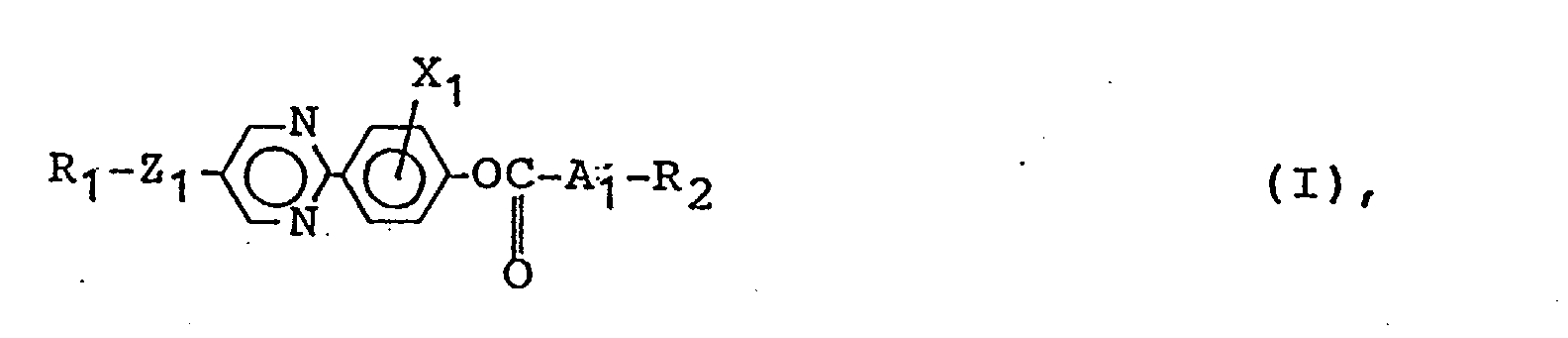
 au moins un composé mésomorphe représenté par la formule (II) suivante :X2 et X3 représentent, respectivement, l'hydrogène, F, Cl, Br, un groupe -CH3, -CN ou -CF3 ; et k est égal à 0 ou 1, sous réserve que Z2 représente une liaison simple lorsque A2 représente un liaison simple, et Z3 représente une liaison simple lorsque A3 représente une liaison simple et k est égal à 0.


- Composition de cristal liquide suivant la revendication 1, dans laquelle le composé mésomorphe de formule (I) est représenté par l'une quelconque des formules (Ia) et (Ib) suivantes :


- Composition de cristal liquide suivant la revendication 1, dans laquelle R1 et R2 dans la formule (I) représentent, respectivement, l'un quelconque des groupes (I-i) à (I-iv) suivants :(I-i) un groupe n-alkyle ayant 1 à 16 atomes de carbone ;(I-ii) un groupe
 (I-iii) un groupe
 (I-iv) un groupe
- Composition de cristal liquide suivant la revendication 1, dans laquelle le composé mésomorphe de formule (II) est représenté par l'une quelconque des formules (IIa) à (IIq) suivantes :





- Composition de cristal liquide suivant la revendication 1, dans laquelle le composé mésomorphe de formule (II) est représenté par l'une quelconque des formules (IIaa) à (IIna) suivantes :


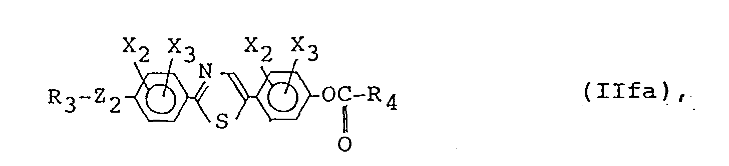





- Composition de cristal liquide suivant la revendication 1, dans laquelle R3 et R4 dans la formule (II) représentent, respectivement, l'un quelconque des groupes (II-i) à (II-iv) suivantes :(II-i) un groupe n-alkyle ayant 2 à 16 atomes de carbone ;(II-ii) un groupe
 (II-iii) un groupe
 (II-iv) un groupe
- Composition de cristal liquide suivant la revendication 1, qui comprend en outre un composé mésomorphe représenté par la formule (III) suivante :


- Composition de cristal liquide suivant la revendication 7, dans laquelle le composé mésomorphe de formule (III) est représenté par l'une quelconque des formules (IIIa) à (IIIf) suivantes :


- Composition de cristal liquide suivant la revendication 8, dans laquelle Z4 et Z5 dans les formules (IIIa) à (IIIf) représentent l'une quelconque des associations (III-i) à (III-v) suivantes :(III-i) Z4 représente une liaison simple et Z5 représente un groupe O-CH2- ;(III-ii) Z4 représente une liaison simple et Z5 représente un groupe -COO-CH2- ;(III-iii) Z4 représente une liaison simple et Z5 représente un groupe -OCO- ;(III-iv) Z4 représente -O- et Z5 représente un groupe -O-CH2- ; et(III-v) Z4 représente -O- et Z5 représente un groupe -COOCH2-.
- Composition de cristal liquide suivant la revendication 1, comprenant en outre au moins un composé mésomorphe en plus des composés mésomorphes de formules (I) et (II).
- Composition de cristal liquide suivant la revendication 10, qui comprend 1 à 90 % en poids au total des composés mésomorphes de formules (I) et (II).
- Composition de cristal liquide suivant la revendication 10, qui comprend 2 à 80 % en poids au total des composés mésomorphes de formules (I) et (II).
- Composition de cristal liquide suivant la revendication 10, qui comprend 4 à 80 % en poids au total des composés mésomorphes de formules (I) et (II).
- Composition de cristal liquide suivant la revendication 7, comprenant en outre au moins un composé mésomorphe en plus des composés mésomorphes de formules (I), (II) et (III).
- Composition de cristal liquide suivant la revendication 14, qui comprend 1 à 99 % en poids au total des composés mésomorphes de formules (I), (II) et (III).
- Composition de cristal liquide suivant la revendication 14, qui comprend 4 à 90 % en poids au total des composés mésomorphes de formules (I), (II) et (III).
- Composition de cristal liquide suivant la revendication 14, qui comprend 6 à 80 % en poids au total des composés mésomorphes de formules (I), (II) et (III).
- Dispositif à cristaux liquides, comprenant une paire de plaques servant d'électrodes et une composition de cristal liquide suivant la revendication 1 disposée entre les plaques servant d'électrodes.
- Dispositif à cristaux liquides suivant la revendication 18, dans lequel le composé mésomorphe de formule (I) est représenté par l'une quelconque des formules (Ia) et (Ib) suivantes :


- Dispositif à cristaux liquides suivant la revendication 18, dans lequel R1 et R2 dans la formule (I) représentent, respectivement, l'un quelconque des groupes (I-i) à (I-iv) suivants :(I-i) un groupe n-alkyle ayant 1 à 16 atomes de carbone ;(I-ii) un groupe
 (I-iii) un groupe
 (I-iv) un groupe
- Dispositif à cristaux liquides suivant la revendication 18, dans lequel le composé mésomorphe de formule (II) est représenté par l'une quelconque des formules (IIa) à (IIq) suivantes : (IIq):

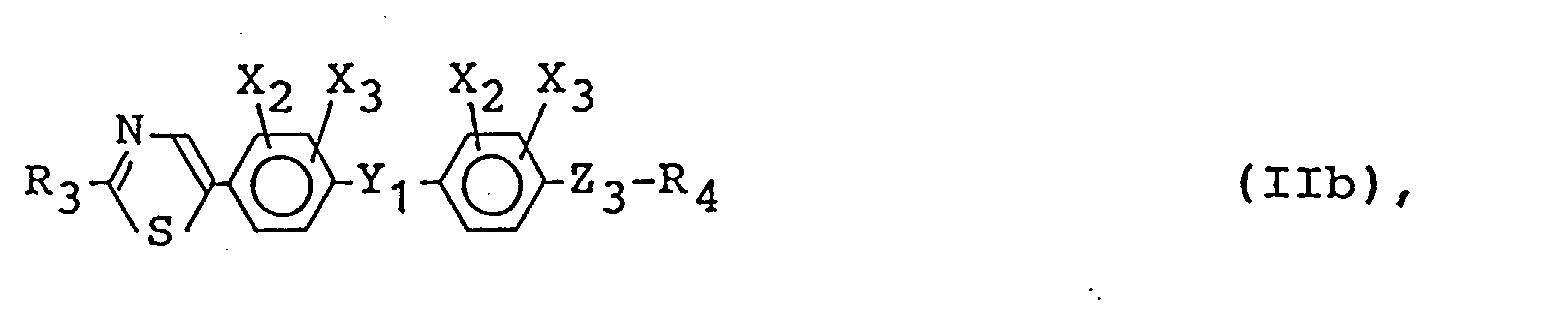


- Dispositif à cristaux liquides suivant la revendication 18, dans lequel le composé mésomorphe de formule (II) est représenté par l'une quelconque des formules (IIaa) à (IIna) suivantes :


- Dispositif à cristaux liquides suivant la revendication 18, dans lequel R3 et R4 dans la formule (II) représentent, respectivement, l'un quelconque des groupes (II-i) à (II-iv) suivants :(II-i) un groupe n-alkyle ayant 2 à 16 atomes de carbone ;(II-ii) un groupe
 (II-iii) un groupe
 (II-iv) un groupe
- Dispositif à cristaux liquides suivant la revendication 18, dans lequel la composition de cristal liquide comprend en outre un composé mésomorphe représenté par la formule (III) suivante :


- Dispositif à cristaux liquides suivant la revendication 18, dans lequel le composé mésomorphe de formule (III) est représenté par l'une quelconque des formules (IIIa) à (IIIf) suivantes :


- Dispositif à cristaux liquides suivant la revendication 25, dans lequel Z4 et Z5 dans les formules (IIIa) à (IIIf) représentent l'une quelconque des associations (III-i) à (III-v) suivantes :(III-i) Z4 représente une liaison simple et Z5 représente un groupe -O-CH2- ;(III-ii) Z4 représente une liaison simple et Z5 représente un groupe -COO-CH2-;(III-iii) Z4 représente une liaison simple et Z5 représente un groupe -OCO- ;(III-iv) Z4 représente -O- et Z5 représente un groupe -O-CH2- ; et(III-v) Z4 représente -O- et Z5 représente un groupe -COOCH2-.
- Dispositif à cristaux liquides suivant la revendication 18, qui comprend en outre une couche de commande d'alignement isolante.
- Dispositif à cristaux liquides suivant la revendication 27, dans lequel la couche de commande d'alignement isolante a été soumise à un frottement.
- Appareil d'affichage comprenant un dispositif à cristaux liquides suivant la revendication 18, et un moyen d'application de tension pour commander le dispositif à cristaux liquides.
- Appareil d'affichage suivant la revendication 29, dans lequel le composé mésomorphe de formule (I) est représenté par l'une quelconque des formules (Ia) et (Ib) suivantes :


- Appareil d'affichage suivant la revendication 29, dans lequel R1 et R2 dans la formule (I) représentent, respectivement, l'un quelconque des groupes (I-i) à (I-iv) suivants :(I-i) un groupe n-alkyle ayant 1 à 16 atomes de carbone ;(I-ii) un groupe
 (I-iii) un groupe
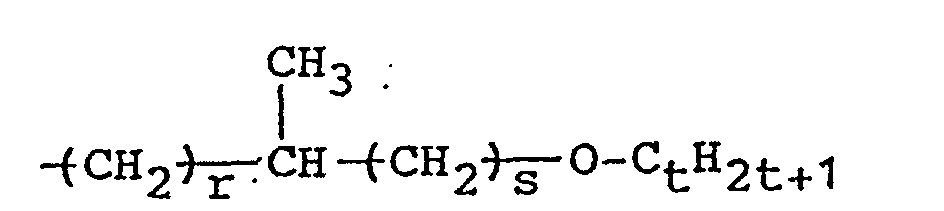 (I-iv) un groupe
- Appareil d'affichage suivant la revendication 29, dans lequel le composé mésomorphe de formule (II) est représenté par l'une quelconque des formules (IIa) à (IIq) suivantes :


- Appareil d'affichage suivant la revendication 29, dans lequel le composé mésomorphe de formule (II) est représenté par l'une quelconque des formules (IIaa) à (IIna) suivantes :



- Appareil d'affichage suivant la revendication 29, dans lequel R3 et R4 dans la formule (II) représentent, respectivement, l'un quelconque des groupes (II-i) à (II-iv) suivants :(II-i) un groupe n-alkyle ayant 2 à 16 atomes de carbone ;(II-ii) un groupe
 (II-iii) un groupe
 (II-iv) un groupe
- Appareil d'affichage suivant la revendication 29, dans lequel la composition de cristal liquide comprend en outre un composé mésomorphe représenté par la formule (III) suivante :


- Appareil d'affichage suivant la revendication 35, dans lequel le composé mésomorphe de formule (III) est représenté par l'une quelconque des formules (IIIa) à (IIIf) suivantes :


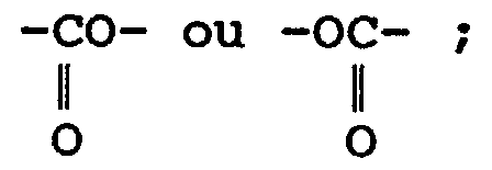

- Appareil d'affichage suivant la revendication 36, dans lequel Z4 et Z5 dans les formules (IIIa) à (IIIf) représentent l'une quelconque des associations (III-i) à (III-v) suivantes :(III-i) Z4 représente une liaison simple et Z5 représente un groupe -O-CH2- ;(III-ii) Z4 représente une liaison simple et Z5 représente un groupe -COO-CH2- ;(III-iii) Z4 représente une liaison simple et Z5 représente un groupe -OCO- ;(III-iv) Z4 représente -O- et Z5 représente un groupe -O-CH2- ; et(III-v) Z4 représente -O- et Z5 représente un groupe -COOCH2-.
- Appareil d'affichage suivant la revendication 29, qui comprend en outre un circuit de commande.
- Appareil d'affichage suivant la revendication 29, qui comprend en outre une source de lumière.
- Procédé d'affichage, comprenant les étapes consistant :à prendre une composition de cristal liquide comprenant :au moins un composé mésomorphe représenté par la formule (I) suivante :

 au moins un composé mésomorphe représenté par la formule (II) suivante :


 à effectuer la commutation du sens d'alignement des molécules de cristal liquide par application de tensions à la composition de cristal liquide pour effectuer l'affichage.
 - Procédé d'affichage suivant la revendication 40, dans lequel le composé mésomorphe de formule (I) est représenté par l'une quelconque des formules (Ia) et (Ib) suivantes :


- Procédé d'affichage suivant la revendication 40, dans lequel R1 et R2 dans la formule (I) représentent, respectivement, l'un quelconque des groupes (I-i) à (I-iv) suivants :(I-i) un groupe n-alkyle ayant 1 à 16 atomes de carbone(I-ii) un groupe
 (I-iii) un groupe
 (I-iv) un groupe
- Procédé d'affichage suivant la revendication 40, dans lequel le composé mésomorphe de formule (II) est représenté par l'une quelconque des formules (IIa) à (IIq) suivantes :


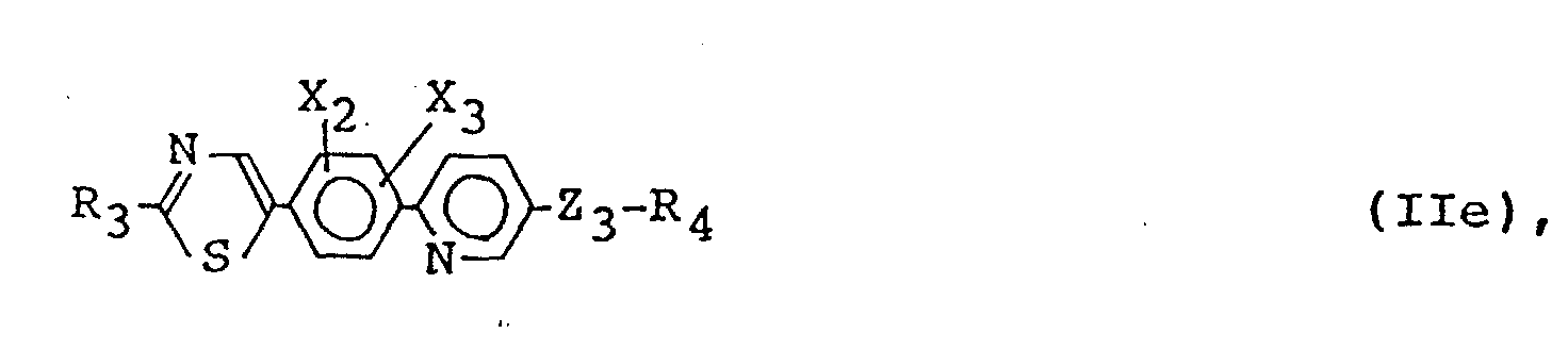


- Procédé d'affichage suivant la revendication 40, dans lequel le composé mésomorphe de formule (II) est représenté par l'une quelconque des formules (IIaa) à (IIna) suivantes :


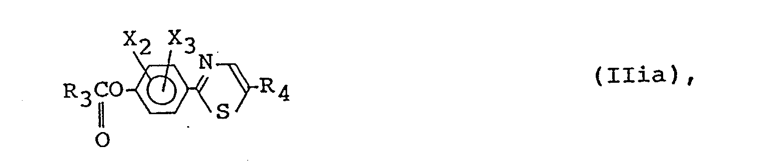


- Procédé d'affichage suivant la revendication 40, dans lequel R3 et R4 dans la formule (II) représentent, respectivement, l'un quelconque des groupes (II-i) à (II-iv) suivants :(II-i) un groupe n-alkyle ayant 2 à 16 atomes de carbone ;(II-ii) un groupe
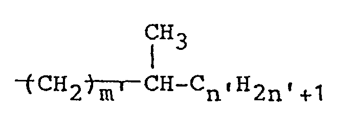 (II-iii) un groupe
 (II-iv) un groupe
- Appareil d'affichage suivant la revendication 40, qui comprend en outre un composé mésomorphe représenté par la formule (III) suivante :


- Procédé d'affichage suivant la revendication 46, dans lequel le composé mésomorphe de formule (III) est représenté par l'une quelconque des formules (IIIa) à (IIIf) suivantes :


- Procédé d'affichage suivant la revendication 47, dans lequel Z4 et Z5 dans les formules (IIIa) à (IIIf) représentent l'une quelconque des associations (III-i) à (III-v) suivantes :(III-i) Z4 représente une liaison simple et Z5 représente un groupe -O-CH2- ;(III-ii) Z4 représente une liaison simple et Z5 représente un groupe -COO-CH2- ;(III-iii) Z4 représente une liaison simple et Z5 représente un groupe -OCO- ;(III-iv) Z4 représente -O- et Z5 représente un groupe -O-CH2-; et(III-v) Z4 représente -O- et Z5 représente un groupe -COOCH2-.
- Procédé d'affichage suivant la revendication 40, dans lequel la composition de cristal liquide comprend en outre au moins un type d'un autre composé mésomorphe autre que les composés mésomorphes de formules (I) et (II).
- Procédé d'affichage suivant la revendication 49, dans lequel la composition de cristal liquide comprend 1 à 90 % en poids au total des composés mésomorphes de formules (I) et (II).
- Procédé d'affichage suivant la revendication 49, dans lequel la composition de cristal liquide comprend 2 à 80 % en poids au total des composés mésomorphes de formules (I) et (II).
- Procédé d'affichage suivant la revendication 49, dans lequel la composition de cristal liquide comprend 4 à 80 % en poids au total des composés mésomorphes de formules (I) et (II).
- Procédé d'affichage suivant la revendication 46, dans lequel la composition de cristal liquide comprend en outre au moins un type d'un autre composé mésomorphe autre que les composés mésomorphes de formules (I), (II) et (III).
- Procédé d'affichage suivant la revendication 53, dans lequel la composition de cristal liquide comprend 1 à 99 % en poids au total des composés mésomorphes de formules (I), (II) et (III).
- Procédé d'affichage suivant la revendication 53, dans lequel la composition de cristal liquide comprend 4 à 90 % en poids au total des composés mésomorphes de formules (I), (II) et (III).
- Procédé d'affichage suivant la revendication 53, dans lequel la composition de cristal liquide comprend 6 à 80 % en poids au total des composés mésomorphes de formules (I), (II) et (III).
Applications Claiming Priority (2)
| Application Number | Priority Date | Filing Date | Title |
|---|---|---|---|
| JP148971/90 | 1990-06-06 | ||
| JP2148971A JP2984322B2 (ja) | 1990-06-06 | 1990-06-06 | 液晶組成物およびこれを含む液晶素子 |
Publications (3)
| Publication Number | Publication Date |
|---|---|
| EP0460624A2 EP0460624A2 (fr) | 1991-12-11 |
| EP0460624A3 EP0460624A3 (en) | 1992-04-15 |
| EP0460624B1 true EP0460624B1 (fr) | 1997-09-10 |
Family
ID=15464771
Family Applications (1)
| Application Number | Title | Priority Date | Filing Date |
|---|---|---|---|
| EP91109167A Expired - Lifetime EP0460624B1 (fr) | 1990-06-06 | 1991-06-05 | Composition liquide cristalline, dispositif à cristal liquide, dispositif d'affichage et procédé d'affichage |
Country Status (5)
| Country | Link |
|---|---|
| US (1) | US5269964A (fr) |
| EP (1) | EP0460624B1 (fr) |
| JP (1) | JP2984322B2 (fr) |
| AT (1) | ATE158012T1 (fr) |
| DE (1) | DE69127583T2 (fr) |
Families Citing this family (5)
| Publication number | Priority date | Publication date | Assignee | Title |
|---|---|---|---|---|
| JP2941937B2 (ja) * | 1990-01-25 | 1999-08-30 | キヤノン株式会社 | 新規化合物、これを含む液晶組成物及びこれを使用した液晶素子並びに表示装置 |
| JP3040921B2 (ja) * | 1993-10-13 | 2000-05-15 | キヤノン株式会社 | 強誘電性液晶素子及びこれを備えた液晶装置 |
| JP3093627B2 (ja) * | 1996-02-09 | 2000-10-03 | キヤノン株式会社 | 液晶表示装置の製造方法 |
| CN101990651B (zh) * | 2008-04-08 | 2014-06-04 | 株式会社V技术 | 液晶显示装置的制造方法及其制造装置 |
| FR3094573B1 (fr) * | 2019-03-29 | 2021-08-13 | Soitec Silicon On Insulator | Procede de preparation d’une couche mince de materiau ferroelectrique |
Family Cites Families (17)
| Publication number | Priority date | Publication date | Assignee | Title |
|---|---|---|---|---|
| JPS59193427A (ja) * | 1983-04-19 | 1984-11-02 | Canon Inc | 液晶装置 |
| US4655561A (en) * | 1983-04-19 | 1987-04-07 | Canon Kabushiki Kaisha | Method of driving optical modulation device using ferroelectric liquid crystal |
| JPS59193426A (ja) * | 1983-04-19 | 1984-11-02 | Canon Inc | 液晶装置 |
| JPS60156046A (ja) * | 1984-01-23 | 1985-08-16 | Canon Inc | 液晶装置 |
| JPS60156047A (ja) * | 1984-01-23 | 1985-08-16 | Canon Inc | 液晶装置 |
| US4721367A (en) * | 1985-04-01 | 1988-01-26 | Canon Kabushiki Kaisha | Liquid crystal device |
| GB2181429B (en) * | 1985-08-13 | 1989-11-15 | Canon Kk | Lactic acid derivative and liquid crystal composition containing same |
| DE3627964C2 (de) * | 1985-08-26 | 2000-11-02 | Samsung Electronic Devices | Ferroelektrische kristallin-flüssige Derivate verzweigter acyclischer chiraler alpha-Chlorcarbonsäuren, Verfahren zu ihrer Herstellung und ihre Verwendung in Gemischen für schnell schaltende Displays in der Optoelektronik |
| JPS6322042A (ja) * | 1986-03-10 | 1988-01-29 | Canon Inc | フルオロアルカン誘導体 |
| DE3718174A1 (de) * | 1987-05-29 | 1988-12-15 | Hoechst Ag | Verwendung von optisch aktiven oxiran-2-carbonsaeureestern als dotierstoffe in fluessigkristallmischungen, diese enthaltende fluessigkristallmischungen und neue optisch aktive oxiran-2-carbonsaeureester |
| JPH0651657B2 (ja) * | 1986-11-10 | 1994-07-06 | キヤノン株式会社 | フルオロアルカン誘導体、それを含む液晶組成物および液晶素子 |
| DE3730859A1 (de) * | 1987-04-16 | 1989-03-30 | Merck Patent Gmbh | Thiazol- und thiadiazol-derivate enthaltende medien mit smektischer fluessigkristalliner phase |
| US5034151A (en) * | 1988-03-28 | 1991-07-23 | Canon Kabushiki Kaisha | Mesomorphic compound, ferroelectric liquid crystal composition containing same and ferroelectric liquid crystal device |
| JP2801269B2 (ja) * | 1989-07-10 | 1998-09-21 | キヤノン株式会社 | 化合物およびこれを含む液晶組成物およびこれを使用した液晶素子 |
| JP2801279B2 (ja) * | 1989-08-25 | 1998-09-21 | キヤノン株式会社 | 化合物およびこれを含む液晶組成物およびこれを使用した液晶素子 |
| JPH03193774A (ja) * | 1989-12-22 | 1991-08-23 | Canon Inc | 光学活性液晶化合物、これを含む液晶組成物およびこれを利用した液晶素子 |
| US5143642A (en) * | 1990-01-13 | 1992-09-01 | Merck Patent Gesellschaft Mit Beschrankter Haftung | Liquid-crystalline medium for electrooptical display elements based on the ECB effect |
-
1990
- 1990-06-06 JP JP2148971A patent/JP2984322B2/ja not_active Expired - Fee Related
-
1991
- 1991-06-05 EP EP91109167A patent/EP0460624B1/fr not_active Expired - Lifetime
- 1991-06-05 US US07/710,773 patent/US5269964A/en not_active Expired - Fee Related
- 1991-06-05 AT AT91109167T patent/ATE158012T1/de not_active IP Right Cessation
- 1991-06-05 DE DE69127583T patent/DE69127583T2/de not_active Expired - Fee Related
Also Published As
| Publication number | Publication date |
|---|---|
| JP2984322B2 (ja) | 1999-11-29 |
| ATE158012T1 (de) | 1997-09-15 |
| JPH0439392A (ja) | 1992-02-10 |
| DE69127583T2 (de) | 1998-02-19 |
| EP0460624A3 (en) | 1992-04-15 |
| US5269964A (en) | 1993-12-14 |
| DE69127583D1 (de) | 1997-10-16 |
| EP0460624A2 (fr) | 1991-12-11 |
Similar Documents
| Publication | Publication Date | Title |
|---|---|---|
| EP0625513B1 (fr) | Composé mésomorphe, composition liquide cristalline le contenant, dispositif l'utilisant, dispositif et méthode d'affichage | |
| EP0415256B1 (fr) | Composé mésomorphe, composition de cristaux liquides contenant ledit composé et dispositif à cristaux liquides utilisant ledit composé | |
| EP0364923B1 (fr) | Composé mésomorphe, compositions de cristaux liquides le contenant et son utilisation dans un dispositif à cristaux liquides | |
| EP0667385B1 (fr) | Composé mésomorphe, composition liquido-cristallique le contenant, dispositif liquido-cristallique utilisant cette composition et appareil indicateur | |
| EP0499222B1 (fr) | Composition liquide cristalline, dispositif à cristal liquide, appareil et méthode d'affichage | |
| EP0499252B1 (fr) | Composition liquide cristalline, dispositif à cristal liquide, appareil et méthode d'affichage | |
| EP0641850B1 (fr) | Composé mésomorphe, composition liquide cristalline le contenant, dispositif à cristaux liquides utilisant la composition, appareil à cristaux liquides et méthode d'affichage | |
| EP0640676B1 (fr) | Composé mésomorphe, composition liquide cristalline le contenant, dispositif à cristaux liquides utilisant la composition, appareil à cristaux liquides et méthode d'affichage | |
| EP0356672B1 (fr) | Composition de cristal liquide smectique chirale ferro-électrique et dispositif l'utilisant | |
| EP0500072B1 (fr) | Composition liquide cristalline, dispositif à cristal liquide, appareil et méthode d'affichage | |
| EP0467260B1 (fr) | Composé mésomorphe et composition liquide cristalline le contenant, utilisation dans un dispositif à cristaux liquides et dispositif d'affichage | |
| EP0440134B1 (fr) | Composé mésomorphe, composition liquido-cristallique le contenant, dispositif liquido-cristallique l'utilisant et appareil indicateur | |
| EP0555843B1 (fr) | Composé mésomorphe, composition de cristaux liquides, dispositif à cristaux liquides, appareil d'affichage et méthode d'affichage | |
| JPH09151179A (ja) | 光学活性化合物、これを含む液晶組成物、それを有する液晶素子、それらを用いた液晶装置及び表示方法 | |
| US5238601A (en) | Ferroelectric chiral smectic liquid crystal composition and liquid crystal device using same | |
| EP0460624A2 (fr) | Composition liquide cristalline, dispositif à cristal liquide, dispositif d'affichage et procédé d'affichage | |
| EP0460703A1 (fr) | Composés mésomorphes, composition à base de cristaux liquides, dispositif à cristaux liquides, dispositif d'affichage et méthode d'affichage | |
| US5409636A (en) | Ferroelectric chiral smectic liquid crystal composition and liquid crystal device using same | |
| EP0499221B1 (fr) | Composé optiquement actif, composition de cristaux liquides, dispositif à cristaux liquides, appareil pour affichage et méthode d'affichage | |
| JP3171370B2 (ja) | 光学活性化合物、それを含有する液晶組成物、それを有する液晶素子及びそれらを用いた液晶装置及び表示方法 | |
| EP0355314B1 (fr) | Composition liquide cristalline ferro-électrique chirale smectique et dispositif l'utilisant | |
| EP0418922B1 (fr) | Composé mésomorphe, composition de cristaux liquides contenant ledit composé et dispositif à cristaux liquides utilisant ledit composé | |
| EP0439170B1 (fr) | Composé mésomorphe, composition liquide cristalline le contenant, dispositif et système d'affichage l'utilisant | |
| EP0347944B1 (fr) | Composition liquide cristalliné ferro-électrique chirale smectique et dispositif l'utilisant | |
| EP0350935B1 (fr) | Composition de cristaux liquides ferro-électriques, chirale smectique et son emploi dans des dispositifs à base de cristaux liquides |
Legal Events
| Date | Code | Title | Description |
|---|---|---|---|
| PUAI | Public reference made under article 153(3) epc to a published international application that has entered the european phase |
Free format text: ORIGINAL CODE: 0009012 |
|
| 17P | Request for examination filed |
Effective date: 19910705 |
|
| AK | Designated contracting states |
Kind code of ref document: A2 Designated state(s): AT BE CH DE DK ES FR GB GR IT LI LU NL SE |
|
| PUAL | Search report despatched |
Free format text: ORIGINAL CODE: 0009013 |
|
| AK | Designated contracting states |
Kind code of ref document: A3 Designated state(s): AT BE CH DE DK ES FR GB GR IT LI LU NL SE |
|
| 17Q | First examination report despatched |
Effective date: 19931210 |
|
| GRAG | Despatch of communication of intention to grant |
Free format text: ORIGINAL CODE: EPIDOS AGRA |
|
| GRAH | Despatch of communication of intention to grant a patent |
Free format text: ORIGINAL CODE: EPIDOS IGRA |
|
| GRAH | Despatch of communication of intention to grant a patent |
Free format text: ORIGINAL CODE: EPIDOS IGRA |
|
| GRAA | (expected) grant |
Free format text: ORIGINAL CODE: 0009210 |
|
| AK | Designated contracting states |
Kind code of ref document: B1 Designated state(s): AT BE CH DE DK ES FR GB GR IT LI LU NL SE |
|
| PG25 | Lapsed in a contracting state [announced via postgrant information from national office to epo] |
Ref country code: IT Free format text: LAPSE BECAUSE OF FAILURE TO SUBMIT A TRANSLATION OF THE DESCRIPTION OR TO PAY THE FEE WITHIN THE PRE;WARNING: LAPSES OF ITALIAN PATENTS WITH EFFECTIVE DATE BEFORE 2007 MAY HAVE OCCURRED AT ANY TIME BEFORE 2007. THE CORRECT EFFECTIVE DATE MAY BE DIFFERENT FROM THE ONE RECORDED.SCRIBED TIME-LIMIT Effective date: 19970910 Ref country code: LI Free format text: LAPSE BECAUSE OF FAILURE TO SUBMIT A TRANSLATION OF THE DESCRIPTION OR TO PAY THE FEE WITHIN THE PRESCRIBED TIME-LIMIT Effective date: 19970910 Ref country code: BE Effective date: 19970910 Ref country code: AT Effective date: 19970910 Ref country code: DK Free format text: LAPSE BECAUSE OF NON-PAYMENT OF DUE FEES Effective date: 19970910 Ref country code: ES Free format text: THE PATENT HAS BEEN ANNULLED BY A DECISION OF A NATIONAL AUTHORITY Effective date: 19970910 Ref country code: CH Free format text: LAPSE BECAUSE OF FAILURE TO SUBMIT A TRANSLATION OF THE DESCRIPTION OR TO PAY THE FEE WITHIN THE PRESCRIBED TIME-LIMIT Effective date: 19970910 Ref country code: GR Free format text: LAPSE BECAUSE OF FAILURE TO SUBMIT A TRANSLATION OF THE DESCRIPTION OR TO PAY THE FEE WITHIN THE PRESCRIBED TIME-LIMIT Effective date: 19970910 Ref country code: NL Free format text: LAPSE BECAUSE OF FAILURE TO SUBMIT A TRANSLATION OF THE DESCRIPTION OR TO PAY THE FEE WITHIN THE PRESCRIBED TIME-LIMIT Effective date: 19970910 |
|
| REF | Corresponds to: |
Ref document number: 158012 Country of ref document: AT Date of ref document: 19970915 Kind code of ref document: T |
|
| REG | Reference to a national code |
Ref country code: CH Ref legal event code: EP |
|
| REF | Corresponds to: |
Ref document number: 69127583 Country of ref document: DE Date of ref document: 19971016 |
|
| ET | Fr: translation filed | ||
| PG25 | Lapsed in a contracting state [announced via postgrant information from national office to epo] |
Ref country code: SE Effective date: 19971210 |
|
| NLV1 | Nl: lapsed or annulled due to failure to fulfill the requirements of art. 29p and 29m of the patents act | ||
| REG | Reference to a national code |
Ref country code: CH Ref legal event code: PL |
|
| PG25 | Lapsed in a contracting state [announced via postgrant information from national office to epo] |
Ref country code: LU Free format text: LAPSE BECAUSE OF NON-PAYMENT OF DUE FEES Effective date: 19980605 |
|
| PLBE | No opposition filed within time limit |
Free format text: ORIGINAL CODE: 0009261 |
|
| STAA | Information on the status of an ep patent application or granted ep patent |
Free format text: STATUS: NO OPPOSITION FILED WITHIN TIME LIMIT |
|
| 26N | No opposition filed | ||
| REG | Reference to a national code |
Ref country code: GB Ref legal event code: IF02 |
|
| PGFP | Annual fee paid to national office [announced via postgrant information from national office to epo] |
Ref country code: GB Payment date: 20030604 Year of fee payment: 13 |
|
| PGFP | Annual fee paid to national office [announced via postgrant information from national office to epo] |
Ref country code: FR Payment date: 20030610 Year of fee payment: 13 |
|
| PGFP | Annual fee paid to national office [announced via postgrant information from national office to epo] |
Ref country code: DE Payment date: 20030612 Year of fee payment: 13 |
|
| PG25 | Lapsed in a contracting state [announced via postgrant information from national office to epo] |
Ref country code: GB Free format text: LAPSE BECAUSE OF NON-PAYMENT OF DUE FEES Effective date: 20040605 |
|
| PG25 | Lapsed in a contracting state [announced via postgrant information from national office to epo] |
Ref country code: DE Free format text: LAPSE BECAUSE OF NON-PAYMENT OF DUE FEES Effective date: 20050101 |
|
| GBPC | Gb: european patent ceased through non-payment of renewal fee |
Effective date: 20040605 |
|
| PG25 | Lapsed in a contracting state [announced via postgrant information from national office to epo] |
Ref country code: FR Free format text: LAPSE BECAUSE OF NON-PAYMENT OF DUE FEES Effective date: 20050228 |
|
| REG | Reference to a national code |
Ref country code: FR Ref legal event code: ST |