EP0460663A1 - Kraftspeicherantrieb für Feuerwehrschnellauftore oder dergleichen - Google Patents
Kraftspeicherantrieb für Feuerwehrschnellauftore oder dergleichen Download PDFInfo
- Publication number
- EP0460663A1 EP0460663A1 EP91109278A EP91109278A EP0460663A1 EP 0460663 A1 EP0460663 A1 EP 0460663A1 EP 91109278 A EP91109278 A EP 91109278A EP 91109278 A EP91109278 A EP 91109278A EP 0460663 A1 EP0460663 A1 EP 0460663A1
- Authority
- EP
- European Patent Office
- Prior art keywords
- frame
- gate
- force
- spring
- telescopic
- Prior art date
- Legal status (The legal status is an assumption and is not a legal conclusion. Google has not performed a legal analysis and makes no representation as to the accuracy of the status listed.)
- Granted
Links
Images

Classifications
-
- E—FIXED CONSTRUCTIONS
- E05—LOCKS; KEYS; WINDOW OR DOOR FITTINGS; SAFES
- E05D—HINGES OR SUSPENSION DEVICES FOR DOORS, WINDOWS OR WINGS
- E05D13/00—Accessories for sliding or lifting wings, e.g. pulleys, safety catches
- E05D13/10—Counterbalance devices
- E05D13/12—Counterbalance devices with springs
- E05D13/123—Counterbalance devices with springs with compression springs
- E05D13/1238—Counterbalance devices with springs with compression springs specially adapted for overhead wings
-
- E—FIXED CONSTRUCTIONS
- E05—LOCKS; KEYS; WINDOW OR DOOR FITTINGS; SAFES
- E05Y—INDEXING SCHEME ASSOCIATED WITH SUBCLASSES E05D AND E05F, RELATING TO CONSTRUCTION ELEMENTS, ELECTRIC CONTROL, POWER SUPPLY, POWER SIGNAL OR TRANSMISSION, USER INTERFACES, MOUNTING OR COUPLING, DETAILS, ACCESSORIES, AUXILIARY OPERATIONS NOT OTHERWISE PROVIDED FOR, APPLICATION THEREOF
- E05Y2201/00—Constructional elements; Accessories therefor
- E05Y2201/40—Motors; Magnets; Springs; Weights; Accessories therefor
- E05Y2201/47—Springs
- E05Y2201/478—Gas springs
-
- E—FIXED CONSTRUCTIONS
- E05—LOCKS; KEYS; WINDOW OR DOOR FITTINGS; SAFES
- E05Y—INDEXING SCHEME ASSOCIATED WITH SUBCLASSES E05D AND E05F, RELATING TO CONSTRUCTION ELEMENTS, ELECTRIC CONTROL, POWER SUPPLY, POWER SIGNAL OR TRANSMISSION, USER INTERFACES, MOUNTING OR COUPLING, DETAILS, ACCESSORIES, AUXILIARY OPERATIONS NOT OTHERWISE PROVIDED FOR, APPLICATION THEREOF
- E05Y2900/00—Application of doors, windows, wings or fittings thereof
- E05Y2900/10—Application of doors, windows, wings or fittings thereof for buildings or parts thereof
- E05Y2900/106—Application of doors, windows, wings or fittings thereof for buildings or parts thereof for garages
-
- E—FIXED CONSTRUCTIONS
- E05—LOCKS; KEYS; WINDOW OR DOOR FITTINGS; SAFES
- E05Y—INDEXING SCHEME ASSOCIATED WITH SUBCLASSES E05D AND E05F, RELATING TO CONSTRUCTION ELEMENTS, ELECTRIC CONTROL, POWER SUPPLY, POWER SIGNAL OR TRANSMISSION, USER INTERFACES, MOUNTING OR COUPLING, DETAILS, ACCESSORIES, AUXILIARY OPERATIONS NOT OTHERWISE PROVIDED FOR, APPLICATION THEREOF
- E05Y2900/00—Application of doors, windows, wings or fittings thereof
- E05Y2900/10—Application of doors, windows, wings or fittings thereof for buildings or parts thereof
- E05Y2900/13—Type of wing
- E05Y2900/132—Doors
Definitions
- the invention relates to the rapid opening of multi-leaf, in particular four-leaf, fire department high-speed doors.
- These wings are - using the example of a four-wing gate - articulated to each other about approximately vertical axes or articulated in the approximately vertical side areas of the frames, otherwise the gate wings located towards the center of the door opening to be closed run in the area of their front edges in ceiling rails.
- These gates must also be used without an intact energy supply system, e.g. the electrical supply network, work and must therefore be equipped with energy stores.
- Gas springs could be used as energy stores to quickly open the gate leaves.
- gas springs have two disadvantages in that, on the one hand, they cannot be adjusted with regard to their working pressure and, on the other hand, they are temperature-dependent with regard to the force or working characteristics they emanate.
- the invention has for its object to make a high-speed door of the type in question adjustable with regard to the opening force and thus selectable with regard to the opening speed, in such a way that a temperature dependency is at least largely avoided.
- an energy store is provided in the form of a telescopic tube device which can be pushed into one another against the force of a compression spring, which is accommodated in it.
- a shock absorber is also provided, against which the door wing or the entire moving door leaf runs directly or indirectly upon transition into its open position.
- the spring telescopic tube is connected at one end to the inside of a door leaf on the frame side, while the other end of this telescopic tube is rotatably held on an extension arm which projects from the running rail or frame into the interior of the equipment hall.
- a lever arm is obtained which pushes the gate wing hinged on the frame side outwards when it is released accordingly.
- the further gate wing located towards the center of the gate, which is guided in a track on the ceiling, may then hang on this gate wing.
- the shock absorption takes place in such a way that a shock absorber is provided on the outside, which engages with one on the outer gate wing or on the one that is closing in the center of the gate.
- This boom can be arranged as an extension or in the area of the roller that engages in the running rail. Due to the arrangement of this stop, its path in the direction of the running rail is predetermined, so that the shock absorber can be aligned precisely in this direction of movement by also fixing it on the frame and arranging its working stroke in the direction of the roller displacement.
- Another solution to the problem provides to fix one end of the spring telescopic tube on the running rail or frame, while the other end is directed towards an inwardly projecting arm of the door leaf, in particular arranged such that the arm about the frame-side hinge axis of the frame side gate leaf can pivot.
- a driver is arranged on the outer telescopic tube, which works with a flexible stop of the shock absorber. In this way, the action on the shock absorber is always provided in its precise working direction. Otherwise, this solution can also be used in connection with the arrangement of the spring telescopic tube described above.
- Another advantage is that such a telescopic tubular spring element can be used retrospectively even with gates already installed, precisely because the spring force can be adjusted.
- powered drives can be provided manually or rope-operated latches that withstand the spring pressure of the energy accumulator.
- these gates get into their closed position by actuating a snapper lock, the bolt of such a snapper lock being operable by hand using a rope.
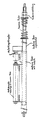
- the two drawing figures show the structure of an energy accumulator designed according to the invention together with shock absorbers in an integrated design
Landscapes
- Engineering & Computer Science (AREA)
- Mechanical Engineering (AREA)
- Special Wing (AREA)
- Closing And Opening Devices For Wings, And Checks For Wings (AREA)
- Vibration Dampers (AREA)
- Portable Nailing Machines And Staplers (AREA)
- Power Conversion In General (AREA)
- Fire-Extinguishing By Fire Departments, And Fire-Extinguishing Equipment And Control Thereof (AREA)
Abstract
Description
- Die Erfindung betrifft das schnelle Öffnen mehrflügeliger, insbesondere vierflügeliger, Feuerwehrschnellauftore. Diese Flügel sind - am Beispiel eines vierflügeligen Tores - um etwa vertikal verlaufende Achsen miteinander gelenkig verbunden bzw. in den etwa vertikalen Seitenbereichen der Zargen angelenkt, im übrigen laufen die zur Mitte der zu verschließenden Toröffnung hin gelegenen Torflügel im Bereich ihrer Stirnkanten in deckenseitigen Laufschienen. Diese Tore müssen im Einsatzfall auch ohne intakte Energieversorgungssysteme, z.B. das Elektroversorgungsnetz, arbeiten und sind daher mit Kraftspeichern auszurüsten.
- Als Kraftspeicher könnten Gasfedern verwendet werden, um die Torflügel schnell zu öffnen. Gasfedern haben jedoch insoweit zwei Nachteile, als sie sich zum einen hinsichtlich ihres Arbeitsdruckes nicht einstellen lassen und zum anderen hinsichtlich der von ihnen ausgehenden Kraft- bzw. Arbeits-Charakteristik temperaturabhängig sind.
- Der Erfindung liegt die Aufgabe zugrunde, ein Schnellauftor der in Rede stehenden Art hinsichtlich der öffnenden Kraft einstellbar und damit hinsichtlich der Öffnungsgeschwindigkeit wählbar zu gestalten, und zwar derart, daß eine Temperaturabhängigkeit zumindest weitgehend vermieden ist.
- Die Aufgabe wird erfindungsgemäß dadurch gelöst, daß ein Kraftspeicher in Gestalt einer Teleskoprohreinrichtung vorgesehen ist, die gegen die Kraft einer - insbesondere in ihr aufgenommenen - Druckfeder ineinander schiebbar ist. In bevorzugter Ausführung ist darüber hinaus ein Stoßdämpfer vorgesehen, gegen den der Torflügel bzw. das gesamte bewegte Torblatt direkt oder indirekt bei Übergang in seine Öffnungslage anläuft. Dabei ist zu beachten, daß die hier abgehandelten Feuerwehrtore im Zweifelsfalle sehr schnell geöffnet werden müssen, so daß erhebliche kinetische Energien frei werden, die bei Erreichen der Öffnungslage des Torblattes stoßgedämpft abgefangen werden müssen.
- Grundsätzlich sind zwei bevorzugte Lösungen anzugeben, nämlich
- 1. Das Federteleskoprohr ist einen Endes an der Innenseite eines zargenseitigen Torflügels angeschlossen, während das andere Ende dieses Teleskoprohres an einem Ausleger drehbar gehalten ist, der von der Laufschiene oder Zarge aus ins Innere der Gerätehalle hineinragt. Auf diese Weise erhält man einen Hebelarm, der den zargenseitig angelenkten Torflügel nach außen hin schiebt, wenn dieser entsprechend freigegeben ist. An diesem Torflügel hängt dann ggfs. der weitere, zur Tormitte hin befindliche Torflügel, der in einer deckenseitigen Laufschiene geführt ist. Die Stoßdämpfung erfolgt derart, daß außenseitig ein Stoßdämpfer vorgesehen ist, der mit einem an dem äußeren Torflügel bzw. demjenigen, der zur Mitte des Tores hin schließend wirksam wird, angreift. Dieser Ausleger kann dabei als Verlängerung oder im Bereich der Laufrolle angeordnet sein, die in die Laufschiene eingreift. Aufgrund der Anordnung dieses Anschlages ist dessen Weg in Richtung der Laufschiene vorbestimmt, so daß der Stoßdämpfer auf diese Bewegungsrichtung hin exakt ausgerichtet werden kann, indem man ihn ebenfalls an der Zarge festlegt und seinen Arbeitshub in Laufrollen-Versetzrichtung anordnet.
- 2. Eine andere Lösung der Aufgabe sieht vor, das eine Ende des Federteleskoprohres an der Laufschiene oder Zarge festzulegen, während das andere Ende auf einen nach innen hin vorstehenden Ausleger des Türblattes gerichtet ist, insbesondere derart angeordnet, daß der Ausleger um die zargenseitige Gelenkachse des zargenseitigen Torflügels verschwenken kann. Hier könnte man ebenfalls die Stoßdämpferanordnung wählen, wie sie bei der vorstehend geschilderten Lösung vorgesehen ist, man hat jedoch hier auch die Möglichkeit, den Stoßdämpfer am inneren Rohr des Teleskoprohres festzulegen und das äußere Rohr mit einem Schlitz zu versehen, so daß es sich gegenüber der Halterung des Stoßdämpfers verschieben kann, wie dies die zugehörige Zeichnung erkennen läßt. Dann wird nämlich ein Mitnehmer auf dem äußeren Teleskoprohr angeordnet, der mit einem flexiblen Anschlag des Stoßdämpfers zusammenarbeitet. Auf diese Weise wird die Beaufschlagung des Stoßdämpfers immer in dessen genauer Arbeitsrichtung vorgesehen. Im übrigen kann man diese Lösung auch im Zusammenhang mit der vorstehend geschilderten Anordnung des Federteleskoprohres verwenden.
- Allgemein ist zur Lösung der Aufgabe folgendes festzuhalten: Die Kennlinie einer Gasfeder ist nicht linear, und zwar dergestalt, daß man zur Einspeicherung der Kraft, was im Zuge des Schließvorganges des Torblattes von Hand geschieht, verhältnismäßig hohe Drücke bzw. Kräfte bei Überführen in die Endoffenlage aufgewandt werden müssen. Demgegenüber ist die Kennlinie einer normalen Druckfeder annähernd linear, weshalb das Einspeichern der Kraft in eine solche Feder leichter zu bewerkstelligen ist, mit der Folge, daß das Torblatt sich leichter in die Schließstellung überführen läßt. Will man die Kräfte bei einer Gasfeder beeinflussen, so muß man in verhältnismäßig aufwendiger und komplizierter Ausgestaltung variable Hebelarme vorsehen. Bei einer Teleskoprohrfeder nach der Erfindung läßt sich dagegen die Federspannung selbst durch entsprechende Verstellung - beispielsweise mittels einer Kontermutterfestlegung - einstellen, so daß
- a) die Feder individuell einstellbar ist und
- b) das Teleskoprohrfederelement für verschiedene Tore verwendet werden kann. Hierzu ist festzuhalten, daß die Torflügelbreiten beispielsweise zwischen 95 cm und 125 cm variieren. Die Betätigung solch unterschiedlich breiter Torflügelelemente ist mit ein und derselben Gasfeder nicht beherrschbar. Die Einstellbarkeit der Teleskoprohrfeder ermöglicht dagegen die Verwendung ein und desselben Elementes für diese unterschiedlichen Torflügelabmessungen.
- Ein weiterer Vorteil besteht darin, daß ein solches Teleskoprohrfederelement auch bei bereits installierten Toren nachträglich eingesetzt werden kann, gerade weil die Einstellbarkeit der Federkraft gegeben ist.
- Weil Feuerwehrhallentüren der hier in Rede stehenden Art wegen Ausfall ansonsten, beispielweise netzabhängig, gespeiste Antriebe von Hand bedienbar sein müssen, lassen sich hand- bzw. seilbetätigte Fallen vorsehen, die gegen den Federdruck des Kraftspeichers standhalten. Anders ausgedrückt gelangen diese Tore in ihre Schließlage unter Betätigen eines Schnepperverschlusses hinein, wobei der Riegel eines solchen Schnepperverschlusses von Hand per Seil betätigbar ist. Diese Voraussetzungen ermöglichen die Anordnung der gesamten Torbetätigungseinrichtung im Bereich der oberen Laufrollenschiene, dergestalt also, daß sie von durchfahrenden Fahrzeugen nicht erreicht wird.
- Die beiden Zeichnungsfiguren zeigen den Aufbau eines erfindungsgemäß ausgebildeten Kraftspeichers nebst Stoßdämpfer in integrierter Bauweise
Claims (4)
- Schnellauftor, insbesondere in mehrflügeliger Ausgestaltung, für Feuerwehr-Gerätehallen oder dergleichen, die unter der Einwirkung von Kraftspeichern schnell und von netzartigen Energieversorgungen unabhängig zu öffnen sind,
dadurch gekennzeichnet,
daß ein oder mehrere Kraftspeicher in Gestalt jeweils einer Teleskoprohreinrichtung vorgesehen sind, deren Teleskopteile gegen die Kraft einer Druckfeder - insbesondere Schraubendruckfeder, ineinander verschiebbar sind. - Tor nach Anspruch 1,
dadurch gekennzeichnet,
daß der bzw. die Torflügel in Richtung ihrer Offenstellung gesehen gegen einen Stoßdämpfer anlaufend ausgebildet ist bzw. sind. - Tor nach Anspruch 1 oder 2,
dadurch gekennzeichnet,
daß das bzw. die Federteleskoprohre einen Endes an der Innenseite eines zargenseitigen Torflügels und anderen Endes an einem Ausleger drehbar gehalten ist bzw. sind, der von der Laufschiene oder Zarge aus ins Innere der Gerätehalle hineinragend ausgebildet ist. - Tor nach Anspruch 1 oder 2,
dadurch gekennzeichnet,
daß das bzw. die Federteleskoprohre einen Endes an der Laufschiene oder Zarge angeordnet und anderen Endes auf einen nach innen hin vorstehenden Ausleger des Torblattes gerichtet ist bzw. sind, insbesondere derart angeordnet, daß der Ausleger um die zargenseitige Gelenkachse des zargenseitigen Torflügels verschwenkbar ist.
Applications Claiming Priority (2)
| Application Number | Priority Date | Filing Date | Title |
|---|---|---|---|
| DE9006387 | 1990-06-06 | ||
| DE9006387U | 1990-06-06 |
Publications (2)
| Publication Number | Publication Date |
|---|---|
| EP0460663A1 true EP0460663A1 (de) | 1991-12-11 |
| EP0460663B1 EP0460663B1 (de) | 1995-05-10 |
Family
ID=6854454
Family Applications (1)
| Application Number | Title | Priority Date | Filing Date |
|---|---|---|---|
| EP91109278A Expired - Lifetime EP0460663B1 (de) | 1990-06-06 | 1991-06-06 | Kraftspeicherantrieb für Feuerwehrschnellauftore oder dergleichen |
Country Status (5)
| Country | Link |
|---|---|
| EP (1) | EP0460663B1 (de) |
| AT (1) | ATE122430T1 (de) |
| DE (2) | DE4118633C2 (de) |
| DK (1) | DK0460663T3 (de) |
| ES (1) | ES2072481T3 (de) |
Cited By (3)
| Publication number | Priority date | Publication date | Assignee | Title |
|---|---|---|---|---|
| DE19715713A1 (de) * | 1997-04-15 | 1998-10-22 | Ibs Industriebarrieren Produkt | Spannvorrichtung für Industriebarrieren |
| WO2019064061A1 (en) * | 2017-09-29 | 2019-04-04 | Titus D.O.O. Dekani | IMPROVEMENTS IN MOTION CONTROL DEVICES |
| CN110952864A (zh) * | 2019-12-18 | 2020-04-03 | 陈李兰 | 一种正常情况防夹高温时快速关门的装置 |
Citations (3)
| Publication number | Priority date | Publication date | Assignee | Title |
|---|---|---|---|---|
| GB899079A (en) * | 1959-08-28 | 1962-06-20 | Hill Aldam And Company Ltd E | Improvements in or relating to door opening apparatus |
| US3698464A (en) * | 1968-08-02 | 1972-10-17 | Bus & Car Co Sa | Folding door for luggage compartment of vehicles such as motor-coaches for example |
| US4427049A (en) * | 1980-12-03 | 1984-01-24 | Belanger, Inc. | Power operated bi-fold strip curtain door assembly |
Family Cites Families (1)
| Publication number | Priority date | Publication date | Assignee | Title |
|---|---|---|---|---|
| DE717717C (de) * | 1938-07-17 | 1942-02-20 | Kaloriferwerk Hugo Junkers G M | Feststellvorrichtung fuer Schiebetore |
-
1991
- 1991-06-06 DK DK91109278.1T patent/DK0460663T3/da active
- 1991-06-06 DE DE4118633A patent/DE4118633C2/de not_active Expired - Fee Related
- 1991-06-06 EP EP91109278A patent/EP0460663B1/de not_active Expired - Lifetime
- 1991-06-06 ES ES91109278T patent/ES2072481T3/es not_active Expired - Lifetime
- 1991-06-06 AT AT91109278T patent/ATE122430T1/de not_active IP Right Cessation
- 1991-06-06 DE DE59105417T patent/DE59105417D1/de not_active Expired - Fee Related
Patent Citations (3)
| Publication number | Priority date | Publication date | Assignee | Title |
|---|---|---|---|---|
| GB899079A (en) * | 1959-08-28 | 1962-06-20 | Hill Aldam And Company Ltd E | Improvements in or relating to door opening apparatus |
| US3698464A (en) * | 1968-08-02 | 1972-10-17 | Bus & Car Co Sa | Folding door for luggage compartment of vehicles such as motor-coaches for example |
| US4427049A (en) * | 1980-12-03 | 1984-01-24 | Belanger, Inc. | Power operated bi-fold strip curtain door assembly |
Cited By (4)
| Publication number | Priority date | Publication date | Assignee | Title |
|---|---|---|---|---|
| DE19715713A1 (de) * | 1997-04-15 | 1998-10-22 | Ibs Industriebarrieren Produkt | Spannvorrichtung für Industriebarrieren |
| WO2019064061A1 (en) * | 2017-09-29 | 2019-04-04 | Titus D.O.O. Dekani | IMPROVEMENTS IN MOTION CONTROL DEVICES |
| CN110952864A (zh) * | 2019-12-18 | 2020-04-03 | 陈李兰 | 一种正常情况防夹高温时快速关门的装置 |
| CN110952864B (zh) * | 2019-12-18 | 2021-07-13 | 嘉兴艾德尔电子科技股份有限公司 | 一种正常情况防夹高温时快速关门的装置 |
Also Published As
| Publication number | Publication date |
|---|---|
| ES2072481T3 (es) | 1995-07-16 |
| DE4118633A1 (de) | 1991-12-12 |
| DE59105417D1 (de) | 1995-06-14 |
| DK0460663T3 (da) | 1995-07-10 |
| EP0460663B1 (de) | 1995-05-10 |
| DE4118633C2 (de) | 1997-10-23 |
| ATE122430T1 (de) | 1995-05-15 |
Similar Documents
| Publication | Publication Date | Title |
|---|---|---|
| DE19733415B4 (de) | Anordnung bestehend aus einer Tür oder einem Fenster und einem Fassadenelement oder einem Festfeldflügel | |
| EP0065109B1 (de) | Scharnier | |
| EP0726379A1 (de) | Schliessfolgeregler für eine zweiflügelige Tür | |
| DE202016001634U1 (de) | Ausstellvorrichtung für einen zumindest parallelabstellbaren und in dieser Lage horizontal verschiebbaren Flügel eines Fensters oder einer Tür | |
| DE3343366C2 (de) | ||
| EP0460663B1 (de) | Kraftspeicherantrieb für Feuerwehrschnellauftore oder dergleichen | |
| DE2421919C3 (de) | Fenster | |
| DE19933082C2 (de) | Automatische Schiebedrehtür | |
| EP0851083B1 (de) | Vertikalschiebefenster | |
| DE4308560A1 (de) | Schließfolgeregelung für eine über Türschließer selbstschließende, einen Standflügel und einen Gangflügel umfassende Tür | |
| EP1801336A1 (de) | Schliessfolgeregelung | |
| CH492859A (de) | Schiebetor | |
| CH688723A5 (de) | Halteorgan, insbesondere Ausstellschere, für Kipp-, Drehkipp- oder Schiebekippfenster. | |
| DE19605744A1 (de) | Vorrichtung zur Schließfolge und/oder Öffnungsfolgeregelung für eine zweiflügelige Tür | |
| DE19600444C2 (de) | Schiebe-Schwenktür | |
| DE19717959A1 (de) | Vorrichtung zum Öffnen, Schließen oder Dämpfen eines Flügels einer Tür, eines Fensters oder dergleichen | |
| EP1247931B1 (de) | Schliessfolgeregler | |
| EP1801337B1 (de) | Vorrichtung zur Schließfolgeregelung für zweiflügelige Drehtüren | |
| EP0204057B1 (de) | Vertikalschiebefenster | |
| EP0505350A1 (de) | Drehscheiben-Schliessfolge- und Verriegelungseinrichtung | |
| DE10001424A1 (de) | Tür mit drehbar in Türbändern gelagerte Türflügel | |
| DE19520231C2 (de) | Torantrieb für ein Garagentor | |
| EP0668426A1 (de) | Beschlag für Fenster oder Türen | |
| EP2302154B1 (de) | Schliessfolgeregelung für eine schiebe-drehtür, insbesondere für brandschutzzwecke | |
| DE1930485A1 (de) | Schwenkschiebetuer,insbesondere fuer Strassen- und Schienenfahrzeuge |
Legal Events
| Date | Code | Title | Description |
|---|---|---|---|
| PUAI | Public reference made under article 153(3) epc to a published international application that has entered the european phase |
Free format text: ORIGINAL CODE: 0009012 |
|
| AK | Designated contracting states |
Kind code of ref document: A1 Designated state(s): AT BE CH DE DK ES FR GB GR IT LI LU NL SE |
|
| RBV | Designated contracting states (corrected) |
Designated state(s): AT BE CH DE DK ES FR GB IT LI NL SE |
|
| 17P | Request for examination filed |
Effective date: 19920605 |
|
| 17Q | First examination report despatched |
Effective date: 19920810 |
|
| RAP1 | Party data changed (applicant data changed or rights of an application transferred) |
Owner name: HOERMANN-GENK NV |
|
| GRAA | (expected) grant |
Free format text: ORIGINAL CODE: 0009210 |
|
| AK | Designated contracting states |
Kind code of ref document: B1 Designated state(s): AT BE CH DE DK ES FR GB IT LI NL SE |
|
| REF | Corresponds to: |
Ref document number: 122430 Country of ref document: AT Date of ref document: 19950515 Kind code of ref document: T |
|
| ET | Fr: translation filed | ||
| ITF | It: translation for a ep patent filed | ||
| REF | Corresponds to: |
Ref document number: 59105417 Country of ref document: DE Date of ref document: 19950614 |
|
| REG | Reference to a national code |
Ref country code: DK Ref legal event code: T3 |
|
| REG | Reference to a national code |
Ref country code: ES Ref legal event code: FG2A Ref document number: 2072481 Country of ref document: ES Kind code of ref document: T3 |
|
| GBT | Gb: translation of ep patent filed (gb section 77(6)(a)/1977) |
Effective date: 19950812 |
|
| PLBE | No opposition filed within time limit |
Free format text: ORIGINAL CODE: 0009261 |
|
| STAA | Information on the status of an ep patent application or granted ep patent |
Free format text: STATUS: NO OPPOSITION FILED WITHIN TIME LIMIT |
|
| 26N | No opposition filed | ||
| PGFP | Annual fee paid to national office [announced via postgrant information from national office to epo] |
Ref country code: GB Payment date: 19980604 Year of fee payment: 8 Ref country code: DK Payment date: 19980604 Year of fee payment: 8 |
|
| PGFP | Annual fee paid to national office [announced via postgrant information from national office to epo] |
Ref country code: ES Payment date: 19980618 Year of fee payment: 8 |
|
| PGFP | Annual fee paid to national office [announced via postgrant information from national office to epo] |
Ref country code: FR Payment date: 19980626 Year of fee payment: 8 |
|
| PGFP | Annual fee paid to national office [announced via postgrant information from national office to epo] |
Ref country code: NL Payment date: 19980630 Year of fee payment: 8 |
|
| PGFP | Annual fee paid to national office [announced via postgrant information from national office to epo] |
Ref country code: SE Payment date: 19990429 Year of fee payment: 9 |
|
| PGFP | Annual fee paid to national office [announced via postgrant information from national office to epo] |
Ref country code: BE Payment date: 19990503 Year of fee payment: 9 |
|
| PG25 | Lapsed in a contracting state [announced via postgrant information from national office to epo] |
Ref country code: GB Free format text: LAPSE BECAUSE OF NON-PAYMENT OF DUE FEES Effective date: 19990606 |
|
| PG25 | Lapsed in a contracting state [announced via postgrant information from national office to epo] |
Ref country code: ES Free format text: LAPSE BECAUSE OF EXPIRATION OF PROTECTION Effective date: 19990607 |
|
| PG25 | Lapsed in a contracting state [announced via postgrant information from national office to epo] |
Ref country code: FR Free format text: THE PATENT HAS BEEN ANNULLED BY A DECISION OF A NATIONAL AUTHORITY Effective date: 19990630 Ref country code: DK Free format text: LAPSE BECAUSE OF NON-PAYMENT OF DUE FEES Effective date: 19990630 |
|
| PG25 | Lapsed in a contracting state [announced via postgrant information from national office to epo] |
Ref country code: NL Free format text: LAPSE BECAUSE OF NON-PAYMENT OF DUE FEES Effective date: 20000101 |
|
| GBPC | Gb: european patent ceased through non-payment of renewal fee |
Effective date: 19990606 |
|
| EUG | Se: european patent has lapsed |
Ref document number: 91109278.1 |
|
| NLV4 | Nl: lapsed or anulled due to non-payment of the annual fee |
Effective date: 20000101 |
|
| REG | Reference to a national code |
Ref country code: DK Ref legal event code: EBP |
|
| PG25 | Lapsed in a contracting state [announced via postgrant information from national office to epo] |
Ref country code: SE Free format text: THE PATENT HAS BEEN ANNULLED BY A DECISION OF A NATIONAL AUTHORITY Effective date: 20000629 |
|
| PG25 | Lapsed in a contracting state [announced via postgrant information from national office to epo] |
Ref country code: BE Free format text: LAPSE BECAUSE OF NON-PAYMENT OF DUE FEES Effective date: 20000630 |
|
| REG | Reference to a national code |
Ref country code: FR Ref legal event code: ST |
|
| BERE | Be: lapsed |
Owner name: HORMANN-GENK N.V. Effective date: 20000630 |
|
| REG | Reference to a national code |
Ref country code: ES Ref legal event code: FD2A Effective date: 20010601 |
|
| PGFP | Annual fee paid to national office [announced via postgrant information from national office to epo] |
Ref country code: CH Payment date: 20030612 Year of fee payment: 13 |
|
| PGFP | Annual fee paid to national office [announced via postgrant information from national office to epo] |
Ref country code: AT Payment date: 20030613 Year of fee payment: 13 |
|
| PGFP | Annual fee paid to national office [announced via postgrant information from national office to epo] |
Ref country code: DE Payment date: 20030822 Year of fee payment: 13 |
|
| PG25 | Lapsed in a contracting state [announced via postgrant information from national office to epo] |
Ref country code: AT Free format text: LAPSE BECAUSE OF NON-PAYMENT OF DUE FEES Effective date: 20040606 |
|
| PG25 | Lapsed in a contracting state [announced via postgrant information from national office to epo] |
Ref country code: LI Free format text: LAPSE BECAUSE OF NON-PAYMENT OF DUE FEES Effective date: 20040630 Ref country code: CH Free format text: LAPSE BECAUSE OF NON-PAYMENT OF DUE FEES Effective date: 20040630 |
|
| PG25 | Lapsed in a contracting state [announced via postgrant information from national office to epo] |
Ref country code: DE Free format text: LAPSE BECAUSE OF NON-PAYMENT OF DUE FEES Effective date: 20050101 |
|
| REG | Reference to a national code |
Ref country code: CH Ref legal event code: PL |
|
| PG25 | Lapsed in a contracting state [announced via postgrant information from national office to epo] |
Ref country code: IT Free format text: LAPSE BECAUSE OF NON-PAYMENT OF DUE FEES Effective date: 20050606 |