EP0460702A2 - Tête magnétique - Google Patents
Tête magnétique Download PDFInfo
- Publication number
- EP0460702A2 EP0460702A2 EP91109364A EP91109364A EP0460702A2 EP 0460702 A2 EP0460702 A2 EP 0460702A2 EP 91109364 A EP91109364 A EP 91109364A EP 91109364 A EP91109364 A EP 91109364A EP 0460702 A2 EP0460702 A2 EP 0460702A2
- Authority
- EP
- European Patent Office
- Prior art keywords
- head
- magnetic
- leading
- tips
- tip
- Prior art date
- Legal status (The legal status is an assumption and is not a legal conclusion. Google has not performed a legal analysis and makes no representation as to the accuracy of the status listed.)
- Granted
Links
Images


Classifications
-
- G—PHYSICS
- G11—INFORMATION STORAGE
- G11B—INFORMATION STORAGE BASED ON RELATIVE MOVEMENT BETWEEN RECORD CARRIER AND TRANSDUCER
- G11B5/00—Recording by magnetisation or demagnetisation of a record carrier; Reproducing by magnetic means; Record carriers therefor
- G11B5/48—Disposition or mounting of heads or head supports relative to record carriers ; arrangements of heads, e.g. for scanning the record carrier to increase the relative speed
- G11B5/52—Disposition or mounting of heads or head supports relative to record carriers ; arrangements of heads, e.g. for scanning the record carrier to increase the relative speed with simultaneous movement of head and record carrier, e.g. rotation of head
- G11B5/53—Disposition or mounting of heads on rotating support
- G11B5/531—Disposition of more than one recording or reproducing head on support rotating cyclically around an axis
-
- G—PHYSICS
- G11—INFORMATION STORAGE
- G11B—INFORMATION STORAGE BASED ON RELATIVE MOVEMENT BETWEEN RECORD CARRIER AND TRANSDUCER
- G11B5/00—Recording by magnetisation or demagnetisation of a record carrier; Reproducing by magnetic means; Record carriers therefor
- G11B5/127—Structure or manufacture of heads, e.g. inductive
- G11B5/187—Structure or manufacture of the surface of the head in physical contact with, or immediately adjacent to the recording medium; Pole pieces; Gap features
-
- G—PHYSICS
- G11—INFORMATION STORAGE
- G11B—INFORMATION STORAGE BASED ON RELATIVE MOVEMENT BETWEEN RECORD CARRIER AND TRANSDUCER
- G11B5/00—Recording by magnetisation or demagnetisation of a record carrier; Reproducing by magnetic means; Record carriers therefor
- G11B5/48—Disposition or mounting of heads or head supports relative to record carriers ; arrangements of heads, e.g. for scanning the record carrier to increase the relative speed
- G11B5/488—Disposition of heads
- G11B5/4893—Disposition of heads relative to moving tape
Definitions
- the present invention relates to a magnetic head for use in audio, video, computer, and other applications, and more particularly to a magnetic head which is of such a structure as to keep good sliding contact with a magnetic tape for recording and reproducing signals at a high rate.
- Recent magnetic recording and reproducing apparatus with rotary head drums for helical scan employ dedicated multitrack magnetic heads for recording and reproducing wide-band video signals, FM audio signals, PCM audio signals, and for erasing signals by flying erasure.
- a helical-scan magnetic recording and reproducing system employs a plurality of magnetic head tips disposed closely to each other and mounted in one window or recess in the outer circumferential surface of a rotary head drum or cylinder.
- the configuration of projecting portions of the head tips, and the curvature thereof in a direction transverse to the tracks are optimized for uniform contact with the magnetic tape.
- Each of the magnetic head tips may be a ferrite head tip or a laminated head tip.
- the laminated head tip comprises a metallic magnetic body or layer sandwiched between nonmagnetic substrates, the metallic magnetic body defining a magnetic path.
- the front configuration or contour of the head tips wears into a large radius of curvature in its transverse direction because of intimate contact with the thick magnetic tape.
- the leading head tip which is brought into initial sliding contact with the magnetic tape is subject to higher pressure than the trailing head tip which is brought into subsequent sliding contact with the magnetic tape.
- the higher pressure is developed because the magnetic tape flexes due to an air stream caused by the rotation of the head drum and also because the magnetic tape and the magnetic head tips move relatively to each other.
- the leading head tip with respect to the direction of rotation of the head drum wears to a larger extent than the trailing head tip. Consequently, the transverse radius of curvature of the leading head tip becomes greater than that of the trailing head tip.
- the thinner magnetic tape is of lower stiffness, it flexes greatly in the transverse direction, and is not sufficiently held in good contact with the leading head tip. As a result, the spacing loss is increased, and the reproduced output of the leading head tip is lower in level than the reproduced output of the trailing head tip. The reduction in the reproduced output of the leading head tip can be observed as a deterioration of the output waveform envelope.
- a multitrack magnetic head for use with a magnetic tape, comprising at least two magnetic head tips disposed adjacent to each other, the head tips being movable with respect to the magnetic tape and including a leading head tip for initial sliding contact with the magnetic tape and a trailing head tip for subsequent sliding contact with the magnetic tape, the leading head tip being made of a material whose wear resistance is greater than that of a material of which the trailing head tip is made.
- the wear resistance is measured in terms of specific wear.
- the magnetic head wears in proportion to the pressure under which it is contacted by the magnetic tape.
- the leading head tip undergoes greater wear than the trailing head tip, and wears into a greater radius of curvature in the radial direction.
- the specific wear of the leading head tip is smaller than that of the trailing head tip, the leading head tip may wear to substantially the same extent as that of the trailing head tip.
- the transverse radius of curvature of the leading head tip remains substantially the same as that of the trailing head tip, so that the leading head tip is held in sliding contact with the magnetic tape in substantially the same manner as the leading head tip is held in sliding contact with the magnetic tape. Any appreciable reduction which would otherwise be produced in the reproduced output of the leading head tip can thus be prevented from occurring.
- the higher wear resistance of the material of the leading head tip than that of the material of the trailing head tip allows the magnetic head to be held in good sliding contact with the magnetic tape, thus preventing a reduction in the reproduced output of the leading head tip owing to a spacing loss, and hence a deterioration of the waveform envelope of the reproduced output of the leading head tip. Even though the head tips are worn, their configurations for sliding contact with the magnetic tape are maintained for good recording and reproducing characteristics.
- Wear resistance of magnetic heads is evaluated in terms of specific wear which is represented by a volume worn per unit running time. More specifically, the specific wear is determined by a wear test. In the wear test, magnetic heads of various materials are mounted on a rotary head drum or cylinder in a magnetic recording and reproducing system, the magnetic heads having equal radii of curvature and project to equal degrees at their tip ends, and the volumes worn of the magnetic heads after a magnetic tape has run against the magnetic heads for a predetermined period of time are divided by the distance the magnetic tape has run. The specific wear is represented by the quotinent. The specific wear of the magnetic heads depends on the magnetic tape used with the magnetic heads and the material of the magnetic heads. The volumes which are worn are determined by measuring the dimensions of the magnetic heads with a feeler-type surface roughness meter before and after the wear test, and the differenceS between the measured volumes are calculated.
- a wear test was conducted using a VHS-format VTR deck, with magnetic heads of various materials mounted on the rotary head drum.
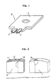
- FIG. 1 shows a multitrack combination magnetic head according to an embodiment of the present invention.
- the magnetic head generally designated by the reference numeral 4, comprises a pair of leading and trailing head tips 1, 2 mounted on an edge of a head base 3 at a spaced interval.
- the leading head tip 1 first comes into sliding contact with a magnetic video tape, as described later on.
- the leading head tip 1 is made of Mn-Zn (manganese-zinc) ferrite whose specific wear has a value of 5.0 ⁇ 10 ⁇ 18m2. As shown in FIG.
- the trailing head tip 2 is of a laminated structure comprising a magnetic body or layer 12 of cobalt-base amorphous alloy which serves as a magnetic path and is sandwiched between nonmagnetic substrates 11 each made of an NiO-TiO2-MgO (nickel oxide-titanium dioxide-magnesium oxide) ceramic material whose specific wear has a value of 7.2 ⁇ 10 ⁇ 18m2.
- NiO-TiO2-MgO nickel oxide-titanium dioxide-magnesium oxide
- FIG. 3 shows a magnetic recording and reproducing apparatus which incorporates the magnetic head shown in FIG. 1.
- the magnetic recording and reproducing apparatus includes a rotary head drum or cylinder assembly 20 which comprises an upper rotary head drum or cylinder 21 and a lower rotary head drum 24.
- the magnetic head 4 is disposed between the upper rotary head drum 21 and the lower rotary head drum 24 and positioned in a window or recess defined in the outer circumferential surface of the upper rotary head drum 21, with the head tips 1, 2 projecting from the outer circumferential surfaces of the rotary head drums 21, 24.
- a magnetic video tape 22 is guided by inclined guide posts 23, 25 disposed one on each side of the rotary head drum assembly 20, so that the magnetic video tape 22 runs against the outer circumferential surface of the rotary head drum assembly 20.
- the head tips 1, 2 serve as leading and trailing heads, respectively, when the magnetic video tape 24 runs in the same direction as the direction in which a rotary head drum assembly 20 rotates. Therefore, the leading head tip 1 is brought into sliding contact with the magnetic video tape 22 earlier than the trailing head tip 2.
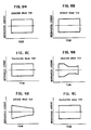
- FIG. 5A shows the waveform envelope of the reproduced output of the leading head tip of the conventional combination magnetic head
- FIG. 5B shows the waveform envelope of the reproduced output of the trailing head tip thereof. It can be seen from FIGS. 5A and 5B that the reproduced output of the leading head tip becomes progressively lower in level with time.
- the leading head tip 1 and the trailing head tip 2 wear to substantially equal degrees because of their materials. Therefore, the transverse radii of curvature of the leading and trailing head tips 1, 2 are substantially the same as each other, and these leading and trailing head tips 1, 2 produce output levels that are essentially the same as each other.
- the waveform envelopes of the reproduced outputs of the leading and trailing head tips 1, 2 are substantially equal to each other and remain substantially constant with time, as shown in FIGS. 4A and 4B.
- Another combination magnetic head according to the present invention may have a leading head tip of a laminated structure comprising a magnetic body or layer sandwiched between substrates each of a TiO2-MgO (titanium dioxide-magnesium oxide) ceramic material whose specific wear has a value of 8.3 ⁇ 10 ⁇ 18m2, and a trailing tip of a laminated structure comprising a magnetic body sandwiched between substrates each of a TiO2-CaO (titanium dioxide-calcium oxide) ceramic material whose specific wear has a value of 15 ⁇ 10 ⁇ 18m2.
- TiO2-MgO titanium dioxide-magnesium oxide
- a combination magnetic head may comprise a leading head tip of ferrite which has a surface for sliding contact with a magnetic video tape, the surface being the (110) face of ferrite, and a trailing head tip of ferrite whose surface for sliding contact with the magnetic video tape is the (111) face of ferrite.
- FIG. 6 shows a multitrack combination magnetic head according to another embodiment of the present invention, the multitrack magnetic head having three head tips.
- FIG. 7 shows the head tips at enlarged scale.
- the magnetic head generally designated by the reference numeral 35, comprises a leading head tip 31, a middle head tip 32, and a trailing head tip 33 which are positioned at spaced intervals and mounted on an edge of a head base 34.
- the magnetic head 35 is mounted on a rotary head drum or cylinder assembly, similar to the rotary head drum assembly 20 shown in FIG. 3, so that the leading head tip 31 comes into sliding contact with the magnetic video tape earlier than the middle and trailing head tips 32, 33.
- the leading head tip 31 is made of Mn-Zn ferrite whose specific wear has a value of 5.0 ⁇ 10 ⁇ 18m2.
- the middle head tip 32 is of a laminated structure comprising a magnetic body which serves as a magnetic path and is sandwiched between nonmagnetic substrates each made of an NiO-TiO2-MgO ceramic material whose specific wear has a value of 7.2 ⁇ 10 ⁇ 18m2.
- the trailing head tip 33 is also of a laminated structure comprising a magnetic body which serves as a magnetic path and is sandwiched between nonmagnetic substrates each made of a TiO2-BaO (titanium dioxide-barium oxide) ceramic material whose specific wear has a value of 10 ⁇ 10 ⁇ 18m2.
- FIGS. 9A and 9B show the waveform envelopes of the reproduced outputs of the leading and middle head tips of the conventional multitrack combination magnetic head, whereas FIG. 9C shows the waveform envelope of the reproduced output of the trailing head tip thereof. It can be seen from FIGS. 9A, 9B, and 9C that the reproduced outputs of the leading and middle head tips become progressively lower in level with time.
- the leading, middle, and trailing head tips 31, 32, 33 have progressively lower wear resistances, and hence their projecting portions wear to substantially equal degrees and have substantially equal radii of curvature in the transverse direction. Therefore, the leading, middle, and trailing head tips 31, 32, 33 produce output levels that are essentially the same as each other.
- the waveform envelopes of the reproduced outputs of the leading, middle, and trailing head tips 31, 32, 33 are substantially equal to each other and remain substantially constant with time, as shown in FIGS. 8A, 8B, and 8C.
- the projecting portions of the leading, middle, and trailing head tips 31, 32, 33 wear substantially equally, the tape running times until they are worn to the gap depth are substantially the same as each other.
- the leading, middle, and trailing head tips 31, 32, 33 have substantially equal service lives.
- Another multitrack combination magnetic head may comprise leading, middle, and trailing head tips each comprising a magnetic body which serves as a magnetic path and is sandwiched between nonmagnetic substrates.
- the substrate of the leading head tip is made of TiO2-MgO ceramic material whose specific wear has a value of 8.3 ⁇ 10 ⁇ 18m2
- the substrate of the middle head tip is made of TiO2-CaO ceramic material whose specific wear has a value of 15 ⁇ 10 ⁇ 18m2
- the substrate of the trailing head tip is made of NiO-MnO (nickel oxide-manganese oxide) ceramic material whose specific wear has a value of 19 ⁇ 10 ⁇ 18m2.
- still another multitrack combination magnetic head may include a leading head tip of Mn-Zn ferrite and successive head tips each comprising a magnetic body serving as a magnetic path and sandwiched between any nonmagnetic substrates whose specific wear is greater than that of Mn-Zn ferrite.
- a multitrack combination magnetic head may comprise a bulk-type leading dummy head tip of Mn-Zn ferrite, a head tip of Mn-Zn ferrite which follows the bulk-type leading dummy head, and a trailing head tip comprising a magnetic body serving as a magnetic path and sandwiched between nonmagnetic substrates whose specific wear is greater than that of Mn-Zn ferrite.
- a multitrack combination magnetic head may comprise three head tips having different values of specific wear which are achieved by employing different faces of single-crystal ferrite or substrate material.
- a multitrack combination magnetic head may comprise four or more head tips positioned in a window or recess defined in the outer circumferential surface of a rotary head drum assembly.
- a magnetic head according to the present invention may be of any of various configurations insofar as the values of specific wear of the head tips are progressively greater from the leading head tip toward the trailing head tip with respect to the direction in which the rotary head drum assembly rotates.
- the principles of the present invention are applicable to not only a laminated multitrack combination magnetic head, but also a bulk-type ferrite magnetic head and a metal-in-gap magnetic head.
- the multitrack magnetic head according to the present invention may be incorporated in not only a magnetic recording and reproducing system with a rotary head drum assembly, but also a magnetic recording and reproducing system with a rotary head drum rotatable between two fixed drums or cylinders, or a magnetic recording and reproducing system with a fixed magnetic head against which a magnetic tape runs at high speed.
Landscapes
- Engineering & Computer Science (AREA)
- Manufacturing & Machinery (AREA)
- Magnetic Heads (AREA)
Applications Claiming Priority (3)
| Application Number | Priority Date | Filing Date | Title |
|---|---|---|---|
| JP2150950A JP2782918B2 (ja) | 1990-06-08 | 1990-06-08 | 磁気ヘッド及び磁気記録再生装置 |
| JP150950/90 | 1990-06-08 | ||
| JP2309779A JP2800400B2 (ja) | 1990-11-14 | 1990-11-14 | 磁気ヘッドおよび磁気記録装置 |
Publications (3)
| Publication Number | Publication Date |
|---|---|
| EP0460702A2 true EP0460702A2 (fr) | 1991-12-11 |
| EP0460702A3 EP0460702A3 (en) | 1992-05-20 |
| EP0460702B1 EP0460702B1 (fr) | 1996-04-03 |
Family
ID=26480373
Family Applications (1)
| Application Number | Title | Priority Date | Filing Date |
|---|---|---|---|
| EP91109364A Expired - Lifetime EP0460702B1 (fr) | 1990-06-08 | 1991-06-07 | Tête magnétique |
Country Status (4)
| Country | Link |
|---|---|
| EP (1) | EP0460702B1 (fr) |
| JP (1) | JP2782918B2 (fr) |
| DE (1) | DE69118441T2 (fr) |
| ES (1) | ES2087928T3 (fr) |
Cited By (1)
| Publication number | Priority date | Publication date | Assignee | Title |
|---|---|---|---|---|
| EP0554867A3 (en) * | 1992-02-05 | 1994-11-30 | Hitachi Ltd | Magnetic recording/reproducing apparatus |
Families Citing this family (1)
| Publication number | Priority date | Publication date | Assignee | Title |
|---|---|---|---|---|
| JP2001118212A (ja) * | 1999-10-14 | 2001-04-27 | Matsushita Electric Ind Co Ltd | 磁気ヘッドおよび磁気記録再生装置 |
Family Cites Families (3)
| Publication number | Priority date | Publication date | Assignee | Title |
|---|---|---|---|---|
| JPS5916127A (ja) * | 1982-07-19 | 1984-01-27 | Canon Inc | 記録再生装置 |
| JPS59144028A (ja) * | 1983-02-07 | 1984-08-17 | Canon Inc | 磁気記録再生装置 |
| JPS6413211A (en) * | 1987-07-06 | 1989-01-18 | Toshiba Corp | Rotary magnetic head device |
-
1990
- 1990-06-08 JP JP2150950A patent/JP2782918B2/ja not_active Expired - Fee Related
-
1991
- 1991-06-07 EP EP91109364A patent/EP0460702B1/fr not_active Expired - Lifetime
- 1991-06-07 ES ES91109364T patent/ES2087928T3/es not_active Expired - Lifetime
- 1991-06-07 DE DE69118441T patent/DE69118441T2/de not_active Expired - Fee Related
Cited By (1)
| Publication number | Priority date | Publication date | Assignee | Title |
|---|---|---|---|---|
| EP0554867A3 (en) * | 1992-02-05 | 1994-11-30 | Hitachi Ltd | Magnetic recording/reproducing apparatus |
Also Published As
| Publication number | Publication date |
|---|---|
| EP0460702A3 (en) | 1992-05-20 |
| DE69118441D1 (de) | 1996-05-09 |
| ES2087928T3 (es) | 1996-08-01 |
| DE69118441T2 (de) | 1996-08-29 |
| JPH0442414A (ja) | 1992-02-13 |
| JP2782918B2 (ja) | 1998-08-06 |
| EP0460702B1 (fr) | 1996-04-03 |
Similar Documents
| Publication | Publication Date | Title |
|---|---|---|
| EP0181263B1 (fr) | Assemblage de tête à contour étroit | |
| CA2066189C (fr) | Servomecanisme de centrage pour enregistreur a balayage helicoidal | |
| US5963401A (en) | Magnetic tape head assembly including modules having a plurality of magneto-resistive head elements | |
| US5321570A (en) | Systems using superimposed, orthogonal buried servo signals | |
| US5543990A (en) | Multitrack magnetic head assembly for scanning a magnetic tape with a plurality of magnetic head tips | |
| GB1571175A (en) | Magnetic transducer apparatus | |
| US3737582A (en) | Flat magnetic heads | |
| EP0460702B1 (fr) | Tête magnétique | |
| GB2098378A (en) | Magnetic head | |
| US4786991A (en) | Magnetic recording/reproduction apparatus | |
| Wildmann | Mechanical limitations in magnetic recording | |
| JP2800400B2 (ja) | 磁気ヘッドおよび磁気記録装置 | |
| EP0451041B1 (fr) | Unité de tambour pour une bande magnétique | |
| EP0356938A3 (fr) | Assemblage de tête rotative d'enregistrement et de surveillance simultanée de données sur une cassette à bande magnétique ou similaires | |
| JPH11175939A (ja) | ダブル磁気ヘッド搭載の回転ヘッドドラム装置 | |
| US5034840A (en) | Magnetic head for a video tape recorder having optimized core tip gap distance and radius of curvature | |
| US5247411A (en) | Multiple-channel magnetic head having plural magnetic head tips mounted on a single head base | |
| JPH0525045Y2 (fr) | ||
| Shoji et al. | A multi-track magnetic recording head for a helical-scan tape system | |
| JPH04134612A (ja) | 回転ドラム装置 | |
| JPS61202388A (ja) | ベリ−ドサ−ボ方式用磁気2重層デイスク | |
| JPH03178024A (ja) | 回転ドラム装置 | |
| Broad | A Guide to Good Magnetic Tape Management Practice for MODAS (Modular Data Acquisition System) Users | |
| JPH02126459A (ja) | 磁気記録再生用ドラム | |
| Franklin | Factors influencing the applications of magnetic tape recording to digital computers |
Legal Events
| Date | Code | Title | Description |
|---|---|---|---|
| PUAI | Public reference made under article 153(3) epc to a published international application that has entered the european phase |
Free format text: ORIGINAL CODE: 0009012 |
|
| 17P | Request for examination filed |
Effective date: 19910607 |
|
| AK | Designated contracting states |
Kind code of ref document: A2 Designated state(s): DE ES FR GB |
|
| PUAL | Search report despatched |
Free format text: ORIGINAL CODE: 0009013 |
|
| AK | Designated contracting states |
Kind code of ref document: A3 Designated state(s): DE ES FR GB |
|
| 17Q | First examination report despatched |
Effective date: 19950327 |
|
| GRAA | (expected) grant |
Free format text: ORIGINAL CODE: 0009210 |
|
| GRAH | Despatch of communication of intention to grant a patent |
Free format text: ORIGINAL CODE: EPIDOS IGRA |
|
| AK | Designated contracting states |
Kind code of ref document: B1 Designated state(s): DE ES FR GB |
|
| REF | Corresponds to: |
Ref document number: 69118441 Country of ref document: DE Date of ref document: 19960509 |
|
| REG | Reference to a national code |
Ref country code: ES Ref legal event code: BA2A Ref document number: 2087928 Country of ref document: ES Kind code of ref document: T3 |
|
| ET | Fr: translation filed | ||
| REG | Reference to a national code |
Ref country code: ES Ref legal event code: FG2A Ref document number: 2087928 Country of ref document: ES Kind code of ref document: T3 |
|
| PLBE | No opposition filed within time limit |
Free format text: ORIGINAL CODE: 0009261 |
|
| STAA | Information on the status of an ep patent application or granted ep patent |
Free format text: STATUS: NO OPPOSITION FILED WITHIN TIME LIMIT |
|
| 26N | No opposition filed | ||
| REG | Reference to a national code |
Ref country code: GB Ref legal event code: IF02 |
|
| PGFP | Annual fee paid to national office [announced via postgrant information from national office to epo] |
Ref country code: GB Payment date: 20050601 Year of fee payment: 15 |
|
| PGFP | Annual fee paid to national office [announced via postgrant information from national office to epo] |
Ref country code: DE Payment date: 20050602 Year of fee payment: 15 |
|
| PGFP | Annual fee paid to national office [announced via postgrant information from national office to epo] |
Ref country code: FR Payment date: 20050608 Year of fee payment: 15 |
|
| PGFP | Annual fee paid to national office [announced via postgrant information from national office to epo] |
Ref country code: ES Payment date: 20050728 Year of fee payment: 15 |
|
| PG25 | Lapsed in a contracting state [announced via postgrant information from national office to epo] |
Ref country code: GB Free format text: LAPSE BECAUSE OF NON-PAYMENT OF DUE FEES Effective date: 20060607 |
|
| PG25 | Lapsed in a contracting state [announced via postgrant information from national office to epo] |
Ref country code: ES Free format text: LAPSE BECAUSE OF NON-PAYMENT OF DUE FEES Effective date: 20060608 |
|
| PG25 | Lapsed in a contracting state [announced via postgrant information from national office to epo] |
Ref country code: DE Free format text: LAPSE BECAUSE OF NON-PAYMENT OF DUE FEES Effective date: 20070103 |
|
| GBPC | Gb: european patent ceased through non-payment of renewal fee |
Effective date: 20060607 |
|
| REG | Reference to a national code |
Ref country code: FR Ref legal event code: ST Effective date: 20070228 |
|
| REG | Reference to a national code |
Ref country code: ES Ref legal event code: FD2A Effective date: 20060608 |
|
| PG25 | Lapsed in a contracting state [announced via postgrant information from national office to epo] |
Ref country code: FR Free format text: LAPSE BECAUSE OF NON-PAYMENT OF DUE FEES Effective date: 20060630 |