EP0460704A2 - Verfahren und Anordnung zur Ortung von schnurlosen Einheiten in einem schnurlosen Grossraumtelefonsystem - Google Patents
Verfahren und Anordnung zur Ortung von schnurlosen Einheiten in einem schnurlosen Grossraumtelefonsystem Download PDFInfo
- Publication number
- EP0460704A2 EP0460704A2 EP91109471A EP91109471A EP0460704A2 EP 0460704 A2 EP0460704 A2 EP 0460704A2 EP 91109471 A EP91109471 A EP 91109471A EP 91109471 A EP91109471 A EP 91109471A EP 0460704 A2 EP0460704 A2 EP 0460704A2
- Authority
- EP
- European Patent Office
- Prior art keywords
- cordless
- request signal
- zone
- unit
- service
- Prior art date
- Legal status (The legal status is an assumption and is not a legal conclusion. Google has not performed a legal analysis and makes no representation as to the accuracy of the status listed.)
- Granted
Links
Images


Classifications
-
- H—ELECTRICITY
- H04—ELECTRIC COMMUNICATION TECHNIQUE
- H04W—WIRELESS COMMUNICATION NETWORKS
- H04W60/00—Affiliation to network, e.g. registration; Terminating affiliation with the network, e.g. de-registration
-
- H—ELECTRICITY
- H04—ELECTRIC COMMUNICATION TECHNIQUE
- H04W—WIRELESS COMMUNICATION NETWORKS
- H04W60/00—Affiliation to network, e.g. registration; Terminating affiliation with the network, e.g. de-registration
- H04W60/02—Affiliation to network, e.g. registration; Terminating affiliation with the network, e.g. de-registration by periodical registration
-
- H—ELECTRICITY
- H04—ELECTRIC COMMUNICATION TECHNIQUE
- H04W—WIRELESS COMMUNICATION NETWORKS
- H04W8/00—Network data management
- H04W8/02—Processing of mobility data, e.g. registration information at HLR [Home Location Register] or VLR [Visitor Location Register]; Transfer of mobility data, e.g. between HLR, VLR or external networks
- H04W8/04—Registration at HLR or HSS [Home Subscriber Server]
-
- H—ELECTRICITY
- H04—ELECTRIC COMMUNICATION TECHNIQUE
- H04W—WIRELESS COMMUNICATION NETWORKS
- H04W84/00—Network topologies
- H04W84/02—Hierarchically pre-organised networks, e.g. paging networks, cellular networks, WLAN [Wireless Local Area Network] or WLL [Wireless Local Loop]
- H04W84/10—Small scale networks; Flat hierarchical networks
- H04W84/16—WPBX [Wireless Private Branch Exchange]
Definitions
- the present invention relates generally to a wide area cordless telephone system which can be coupled to public or private switched telephone networks, and more specifically to such a system which is able to effectively locate cordless units therein.
- a wide area cordless telephone system is designed to serve a relatively wide business area such as occurs within a building, factory, etc., and which is previously divided into a plurality of small service zones.
- An access or fixed station is provided in each of the service zones for establishing communications between the public or private switched telephone network and a plurality of cordless (or mobile) units located therein.
- FIG. 1 schematically depicts the overall layout of a wide area cordless telephone system.
- each of the service zones 11-22 is in actual practice inevitably irregularly shaped due to varying electrical field strength of signals from the corresponding access unit.
- cordless units 40, 42 are illustrated and are shown as being located within the service zones 11, 16 respectively, in this particular example.
- Each of the access stations 11 to 22 is coupled to a radio control unit (RCU) 42 which is in turn coupled to a service console 44 and to a private branch exchange 46.
- RCU radio control unit
- Cordless units in the telephone network system shown in Fig. 1, may access a public switched telephone network denoted by 48 via the private branch exchange 46.
- the RCU 42 In order to establish communications between the cordless units employed in the wide area cordless telephone system, it is absolutely necessary that the RCU 42 is able to exactly locate all of the cordless units. To this end, when the cordless unit (for example) issues a unit location registration request signal (frequently referred to merely as "request signal" for simplicity), a known technique deals with the request signal as follows.
- the cordless unit 40 issues a request signal and (b) each of the access stations 11-22 has received the request signal from the unit 40 and relays the request signal to the RCU 42 after adding thereto an electrical field strength of the request signal received.
- the RCU 42 compares the electrical field strengths (viz., signal levels) applied via a plurality of the access stations ll-22, and determines the strongest electrical field strength (viz., the highest signal level) and determines the location of the cordless unit 40 based on this parameter. In the event that the electrical field strength information applied from the access station 11 is the strongest, the RCU 42 responds by determining the location of the cordless unit 40 as being service zone ll.
- Another object of the present invention is to provide a method by which the signal level comparison operation at the radio control unit can extensively be reduced.
- Another object of the present invention to provide an arrangement of effectively locating the cordless unit in the wide area cordless telephone system.
- Still another object of the present invention is to provide an arrangement by which the signal level comparison operation at the radio control unit can extensively be reduced.
- a first aspect of the present invention is deemed to come in a method of locating cordless units in a telephone system wherein a service area is previously divided into a plurality of small service zones and wherein a plurality of cordless units are provided for establishing communications with a system controller via a plurality of access stations, the system controller locating the cordless units and storing therein location data thereof, each of the cordless units also storing the location data thereof applied from the system controller, the method comprising the steps of: (a) allowing a cordless unit to issue a request signal by which a cordless unit location is performed; (b) receiving the request signal at an access station, the access station checking to determine if the request signal applied thereto is issued from a cordless unit whose location data indicates a service zone belonging to a predetermined service zones; and (c) in the event that the cordless unit location data applied to the access station is found to fall within the predetermined service zones, the access station relays the request signal applied thereto, together with a signal level of the request signal
- a second aspect of the present invention is deemed to come in an arrangement of locating cordless units in a telephone system wherein a service area is previously divided into a plurality of small service zones and wherein a plurality of cordless units are provided for establishing communications with a system controller via a plurality of access stations, the system controller locating the cordless units and storing therein location data thereof, each of the cordless units also storing the location data thereof applied from the system controller, the arrangement comprising: means for allowing a cordless unit to issue a request signal by which a cordless unit location is performed; and means for receiving the request signal at an access station, the access station checking to determine if the request signal applied thereto is issued from a cordless unit whose location data indicates a service zone belonging to a predetermined service zones; wherein in the event that the cordless unit location data applied to the access station is found to fall within the predetermined service zones, the access station relays the request signal applied thereto, together with a signal level of the request signal, to the system controller.
- Fig. 2 schematically illustrates an example of the cordless unit 40 (Fig. 1) in block diagram form. It should be noted that each of the other cordless units used in the wide area cordless system is configured in the same manner as the unit 40.
- the cordless unit 40 includes a keypad 50, a location registration request button 52 and a speech button 54.
- the keypad 50 is coupled to a controller 56 which is in turn connected to a memory 58, a transmitter (TX) 60 and a receiver (RX) 62.
- the memory 58 stores: a cordless unit identifier (ID) previously assigned thereto; and a service zone ID which is subject to renewal when the unit 40 moves to another service Zone.
- ID cordless unit identifier
- the call request is transmitted via the transmitter 62, a duplexer 64 and an antenna 66.
- the cordless unit 40 is further provided with a speaker 68 and a microphone 70.
- a normal speech operation of the cordless unit 40 is well known in the art and is not directly concerned with the instant invention, so that a description thereof is omitted for the sake of simplicity.
- the user When the user wishes to register the zone in which the cordless unit 40 is located, at the radio control unit 42 (Fig. 1), the user pushes the button 52.
- the controller 56 in response to the output from the button 52, sends a location registration request signal through the transmitter 60, the duplexer 64 and the antenna 66.
- the code format of the request signal is shown in Fig. 3. As shown, the code format includes a synchronizing code 72, a control code 74, a cordless unit identifier (ID) 76 and a service zone ID 78.
- the synchronising code 72 is used to synchronize operations of modulation and demodulation and consists of l6 bits merely by way of example, while the control code 74 specifies a cordless unit location registration request signal, an originating call, an incoming call, etc.
- the unit ID 76 which corresponds to the unit ID stored in the memory 58 of the unit 40, distinguishes which cordless unit has issued the request signal.
- the service zone ID 78 corresponds to the service zone data stored in the memory 58. In other words, if the cordless unit 40 has previously stored the service zone ll specified by the access station 11, then the zone ID 78 contains "ll".
- the zone ID 78 defaults to "00" merely by way of example.
- the cordless unit 40 is newly installed in the system, (b) the content of the memory 58 has been erased due to battery change, etc.
- Fig. 4 schematically illustrates the access station ll in block diagram form.
- Each of the other access stations l2-22 is configured in the same manner as the station ll.
- the access station 11 includes two transmitters 80, 82, two receivers 84, 86, a controller 88, a memory 90 and a duplexer 92 coupled to an antenna 94.
- the access station ll communicates with the cordless unit 40 and may also communicate with other cordless units beyond the zone boundaries.
- the controller 88 supervises the overall operation of the access station ll, while the memory 90 stores the service zone data (viz., station number) previously assigned thereto via input at the service console 44 and which has applied thereto via the radio control unit 42.
- the operations of the blocks 80, 82, 84, 86 and 92 are not directly concerned with the present invention and further are well known in the art. Accordingly, a detailed description thereof will be omitted for brevity.
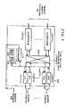
- Fig. 5 schematically shows the radio control unit 42 in block diagram form.
- the control unit 42 includes a plurality of pairs of transmitter and receiver, respectively denoted by (100R(1), 100T(l)), ..., (l00R(n), l00T(n)), a time-division switching unit (TDSW) l02, a plurality of interfaces l04(l), ..., 104(k) interconnected between the TDSM 102 and the private branch exchange 46.
- the TDSW 102 is a unit for providing a common path with separate time intervals assigned to each of the simultaneous calls, as is well known in the art.
- the radio control unit 42 further includes a memory 106 and a controller 112.
- the memory 106 includes a RAM (Random Access Memory) 108 and a ROM (Read Only Memory) 110.
- the RAM l08 stores the data listed below which are related with the instant invention.
- the ROM ll0 stores firmware by which the overall operations of the RCU 42 is controlled.
- the frequencies of the receivers 100R(1)-100R(n) and transmitters 100T(1)-100T(n) are determined by the controller 112 using the firmware.
- the firmware is not directly related with the instant invention.
- the controller 112 compares the electrical field strengths (viz., the signal levels) of the aforesaid request signals which are received by the access stations and then applied to the RCU 42, and determines the strongest electrical field strength based on this parameter.
- the zone number which corresponds to the highest signal level, is stored in the RAM 108. More specifically, the zone number thus determined is registered as a new zone number of a given cordless unit.
- the RCU 42 supplies the cordless unit, which has requested the unit location registration, with a reply signal indicating the determined zone number. It should be noted that only the access station which has issued the request signal with the highest level is allowed to receive the reply signal.
- the code format of the reply signal is shown in Fig. 3.
- the cordless unit in question thus stores the new zone number in the memory 58.
- the present invention will be discussed in detail hereinlater. It should be noted that if the request signal issued from a given cordless (mobile) unit contains service zone data "00" in zone ID 78 (Fig. 3), the operation for locating the cordless unit is implemented in a manner as the known operation. That is to say, the access stations each of which has received the request signal, supplies the RCU 42 with the request signal received and the signal level thereof. The RCU 42 compares all of the signal levels applied thereto from the access stations, and responds by determining the highest signal level.
- the cordless unit 40 remains in the waiting state (step 150) until the button 52 is pressed.
- Step l52 checks to see if the button 52 is pressed, and if the answer is affirmative, the program goes to step 154 wherein the request signal is sent to the access station 11. If the zone data "11" has been stored in the memory 58, the service zone ID 78 (Fig. 3) of the request signal indicates the zone data "11". Following this, the program goes to step 166 of Fig. 8.
- Step 168 checks to see if the request signal is applied to the station 11 from the unit 40 (step 168). If the answer is affirmative then the program goes to step 170. It is assumed that the zone ID of the request signal from the unit 40 contains the zone data "11". Therefore, step 172 is executed. In this case, the zone ID 78 of the request signal indicates the zone data "11" and hence the station 11 supplies the RCU 42 with the request signal and the signal level thereof (step 174).
- the zone ID of the request signal is checked to determine if the zone ID applied to a given access station belongs to a predetermined zone group. More specifically, the zone group consists of a given zone and the zones directly adjacent thereto. This zone grouping is able to extensively reduce the comparison operation at the radio control unit 42 as will be understood as the description further proceeds.
- the RCU 42 remains in the waiting state thereof (step 182).
- step 186 is executed.
- the controller ll2 of the RCU 42 compares the signal levels received and determines the highest level.
- the RCU 42 applies a unit location indicating signal to the access station which has issued the request signal having the highest level (step l88).
- the cordless unit location data in the RAM l08 is renewed (step 188).
- step 178 checks to see if the access station 11 is supplied with the unit location indicating signal from the RCU 42. Since the request signal from the access station 11 has been assumed to have the highest level, the answer is affirmative at step 178 and hence next step 180 is executed. That is to say, the access station 11 supplies the cordless unit 40 with the reply signal wherein the located zone data "11" is included in this particular case. Following this, the program goes to step l60 of the flowchart shown in Fig. 6.
- a step 160 a check is performed to determine if the unit 40 receives the reply signal. Since the answer is affirmative in this case, the next step 162 is executed. Thus, the unit 40 stores the zone data "11" in the predetermined storage portion of the memory 58 under control of the controller 56. If the unit 40 initially holds the zone data "11" then the resultant zone data remains unchanged.
- the zone data ID takes the zone data "00" (step 154 of Fig. 6). Further, the program goes to step 174 via step 170 (Fig 8) and then to Steps 184, 186 and l88 (Fig. 9). It has been assumed that the request signal issued from the access station 11 has the highest level, and accordingly the cordless unit 40 stores the zone data "11" (step 162) in the same manner as mentioned above.
- Fig. 7 wherein there is shown a flowchart for describing another operation of the unit 40. It is assumed in this case that: (a) the cordless unit 40 moves into a service zone N (not shown) remote from the zones shown in Fig. 1 while holing the zone data "ll" therein and (b) the request signal from the unit 40 does not reach any of the service zones ll-l7.
- the case where the unit 40 initially stores no zone data is not referred to in that such a case will be understood without difficulty from the above-mentioned descriptions.
- the flowchart of Fig. 7 differs from that of Fig. 6 in that step l64 is executed in the flowchart of Fig. 7.
- each of steps of Fig. 7 is denoted by the same numeral as the counterpart but is given a prime.
- the program of Fig. 7 exits after the execution of step l54' and enters the flowchart of Fig, 8.
- the answer is NO and hence no reply signal is applied from the access station 11 to the unit 40 .
- the answer is NO, so that step l64' is executed for clearing the zone data storage portion of the memory 58.
- the zone data "00" is applied to the zone ID 78 of the request signal at step l54'.
- the unit 40 finally stores the zone data "N" in the memory 58.
- Fig. 10 shows a flowchart which illustrates another operation of the cordless unit 40 (for example)(second embodiment).
- the request signal is automatically issued at predetermined time intervals (30 seconds merely by way of example) at step 200.
- the remaining steps of Fig. 10 flowchart are exactly the same as the corresponding steps shown in Fig. 6.
- the Fig. 10 flowchart enables the cordless units to be periodically located. Accordingly, it can avoid a problem such that a given cordless unit inadvertently moves to a remote service zone without manual operation for location renewal.
Landscapes
- Engineering & Computer Science (AREA)
- Computer Networks & Wireless Communication (AREA)
- Signal Processing (AREA)
- Mobile Radio Communication Systems (AREA)
Applications Claiming Priority (2)
| Application Number | Priority Date | Filing Date | Title |
|---|---|---|---|
| JP151088/90 | 1990-06-08 | ||
| JP2151088A JP2833831B2 (ja) | 1990-06-08 | 1990-06-08 | 無線電話システムにおける位置登録方式 |
Publications (3)
| Publication Number | Publication Date |
|---|---|
| EP0460704A2 true EP0460704A2 (de) | 1991-12-11 |
| EP0460704A3 EP0460704A3 (en) | 1993-04-14 |
| EP0460704B1 EP0460704B1 (de) | 1997-09-03 |
Family
ID=15511067
Family Applications (1)
| Application Number | Title | Priority Date | Filing Date |
|---|---|---|---|
| EP91109471A Expired - Lifetime EP0460704B1 (de) | 1990-06-08 | 1991-06-10 | Verfahren und Anordnung zur Ortung von schnurlosen Einheiten in einem schnurlosen Grossraumtelefonsystem |
Country Status (6)
| Country | Link |
|---|---|
| US (1) | US5442684A (de) |
| EP (1) | EP0460704B1 (de) |
| JP (1) | JP2833831B2 (de) |
| AU (1) | AU653723B2 (de) |
| CA (1) | CA2044202C (de) |
| DE (1) | DE69127503T2 (de) |
Families Citing this family (14)
| Publication number | Priority date | Publication date | Assignee | Title |
|---|---|---|---|---|
| US5519760A (en) | 1994-06-22 | 1996-05-21 | Gte Laboratories Incorporated | Cellular network-based location system |
| JPH0856378A (ja) * | 1994-08-12 | 1996-02-27 | Saitama Nippon Denki Kk | 移動体パケット通信方式 |
| WO1996021329A1 (en) * | 1994-12-30 | 1996-07-11 | Telefonaktiebolaget Lm Ericsson | System and method relating to cellular communications |
| KR100222734B1 (ko) * | 1996-07-15 | 1999-10-01 | 유기범 | 발신 전용 휴대 전화 시스템을 이용한 사설 교환기용 무선 정합 장치 |
| KR19980013943A (ko) * | 1996-08-05 | 1998-05-15 | 김광호 | 개선된 착신 및 핸드오버 서비스를 위한 디지털 무선전화시스템 |
| US5995843A (en) * | 1996-12-18 | 1999-11-30 | Telefonaktiebolaget Lm Ericsson | Method and arrangement for using a mobile phone in a wireless office network |
| JP2947280B1 (ja) * | 1998-07-28 | 1999-09-13 | 日本電気株式会社 | 位置登録制御方法 |
| WO2000018041A2 (en) * | 1998-09-18 | 2000-03-30 | Harris Corporation | Distributed trunking mechanism for vhf networking |
| US6996088B1 (en) | 1998-09-18 | 2006-02-07 | Harris Corporation | Distributed trunking mechanism for VHF networking |
| US6269246B1 (en) | 1998-09-22 | 2001-07-31 | Ppm, Inc. | Location determination using RF fingerprinting |
| US6393294B1 (en) * | 1998-09-22 | 2002-05-21 | Polaris Wireless, Inc. | Location determination using RF fingerprinting |
| US6980524B1 (en) * | 1999-05-20 | 2005-12-27 | Polytechnic University | Methods and apparatus for routing in a mobile ad hoc network |
| US7366492B1 (en) | 2002-05-03 | 2008-04-29 | Verizon Corporate Services Group Inc. | Method and system for mobile location detection using handoff information |
| JP2012099933A (ja) * | 2010-10-29 | 2012-05-24 | Fujitsu Ltd | 電子機器、画像管理方法、および画像管理プログラム |
Family Cites Families (9)
| Publication number | Priority date | Publication date | Assignee | Title |
|---|---|---|---|---|
| GB8419003D0 (en) * | 1984-07-25 | 1984-08-30 | Racal Res Ltd | Portable telephones |
| GB8619875D0 (en) * | 1986-08-15 | 1986-09-24 | British Telecomm | Communications system |
| JP2566948B2 (ja) * | 1987-04-03 | 1996-12-25 | 日本電気株式会社 | 広域コ−ドレス電話方式 |
| JP2693761B2 (ja) * | 1987-04-03 | 1997-12-24 | 日本電気株式会社 | 移動通信方式 |
| DE3716320A1 (de) * | 1987-05-15 | 1988-11-24 | Bosch Gmbh Robert | Verfahren zum bestimmen des ungefaehren aufenthaltsortes einer mobilen funkstation |
| JP2516983B2 (ja) * | 1987-06-19 | 1996-07-24 | 松下通信工業株式会社 | 無線電話装置 |
| JP2624760B2 (ja) * | 1988-04-01 | 1997-06-25 | 株式会社日立製作所 | 移動無線電話システム |
| US5054110A (en) * | 1989-12-29 | 1991-10-01 | Motorola, Inc. | Multi-site dispatching system cell registration |
| JP2806591B2 (ja) * | 1990-02-08 | 1998-09-30 | 日本電気株式会社 | 無線電話システムの着信方式 |
-
1990
- 1990-06-08 JP JP2151088A patent/JP2833831B2/ja not_active Expired - Lifetime
-
1991
- 1991-06-10 EP EP91109471A patent/EP0460704B1/de not_active Expired - Lifetime
- 1991-06-10 CA CA002044202A patent/CA2044202C/en not_active Expired - Fee Related
- 1991-06-10 DE DE69127503T patent/DE69127503T2/de not_active Expired - Lifetime
- 1991-06-11 AU AU78317/91A patent/AU653723B2/en not_active Expired
-
1994
- 1994-01-13 US US08/181,878 patent/US5442684A/en not_active Expired - Lifetime
Also Published As
| Publication number | Publication date |
|---|---|
| CA2044202C (en) | 1996-12-31 |
| JP2833831B2 (ja) | 1998-12-09 |
| EP0460704B1 (de) | 1997-09-03 |
| CA2044202A1 (en) | 1991-12-09 |
| DE69127503T2 (de) | 1998-01-08 |
| JPH0443791A (ja) | 1992-02-13 |
| AU653723B2 (en) | 1994-10-13 |
| AU7831791A (en) | 1991-12-12 |
| DE69127503D1 (de) | 1997-10-09 |
| EP0460704A3 (en) | 1993-04-14 |
| US5442684A (en) | 1995-08-15 |
Similar Documents
| Publication | Publication Date | Title |
|---|---|---|
| US4839892A (en) | Concentrator system capable of completing emergency calls under congested traffic | |
| US6314299B1 (en) | Method and home base station for setting up connections for a mobile station using an organization channel and station identifiers | |
| CA1236606A (en) | Cordless telephone system | |
| US4144409A (en) | Mobile radio communication control system for preventing erroneous reception of control signals | |
| CA1166316A (en) | Cellular high capacity mobile radiotelephone system with fleet-calling arrangement for dispatch service | |
| US5742904A (en) | Method of providing emergency alarm support via an alternative radio communication system | |
| US5438608A (en) | Mobile radio communication system having base stations and radio terminals each having tenant identification data storage for storing tenant ID data | |
| EP0631417B1 (de) | Verfahren und Steuereinrichtung für ein Funktelefonsystem | |
| US5454028A (en) | Cordless key telephone system having zone switching function | |
| EP0460704B1 (de) | Verfahren und Anordnung zur Ortung von schnurlosen Einheiten in einem schnurlosen Grossraumtelefonsystem | |
| US6163680A (en) | Two way radio communication system and method for establishing communication | |
| US4897864A (en) | Control method and appartus for a radio telephone system | |
| EP0299515A2 (de) | Verfahren zur Verbindung eines schnurlosen Telefons über Funk | |
| JPS6355826B2 (de) | ||
| EP0899928B1 (de) | Kommunikationsverfahren in einem schnurlosen Telefonsystem | |
| JP2880360B2 (ja) | ディジタルコードレス電話機 | |
| JPH0541687A (ja) | 基地局選択方式 | |
| KR100265430B1 (ko) | 비상호출수신방법및장치 | |
| KR0135963B1 (ko) | 구내 무선전화 시스템의 휴대장치 제어방법 | |
| JP4447335B2 (ja) | 移動体通信システムにおける緊急通信処理システム及び方法 | |
| JP2981352B2 (ja) | ディジタルコードレス電話機 | |
| KR100240449B1 (ko) | 주파수 공용통신 시스템의 그룹 호출방법 | |
| CA2046254C (en) | Extended range cordless telephone system | |
| CA1286811C (en) | Method of connecting a cordless telephone by radio | |
| JP2001119339A (ja) | 無線通信システムと無線通信方法 |
Legal Events
| Date | Code | Title | Description |
|---|---|---|---|
| PUAI | Public reference made under article 153(3) epc to a published international application that has entered the european phase |
Free format text: ORIGINAL CODE: 0009012 |
|
| 17P | Request for examination filed |
Effective date: 19910703 |
|
| AK | Designated contracting states |
Kind code of ref document: A2 Designated state(s): DE FR GB NL SE |
|
| PUAL | Search report despatched |
Free format text: ORIGINAL CODE: 0009013 |
|
| AK | Designated contracting states |
Kind code of ref document: A3 Designated state(s): DE FR GB NL SE |
|
| 17Q | First examination report despatched |
Effective date: 19950619 |
|
| RAP1 | Party data changed (applicant data changed or rights of an application transferred) |
Owner name: NEC CORPORATION Owner name: NTT MOBILE COMMUNICATIONS NETWORK INC. |
|
| RAP1 | Party data changed (applicant data changed or rights of an application transferred) |
Owner name: NEC CORPORATION Owner name: NIPPON TELEGRAPH AND TELEPHONE CORPORATION Owner name: NTT MOBILE COMMUNICATIONS NETWORK INC. |
|
| RAP1 | Party data changed (applicant data changed or rights of an application transferred) |
Owner name: NEC CORPORATION Owner name: NIPPON TELEGRAPH AND TELEPHONE CORPORATION Owner name: NTT MOBILE COMMUNICATIONS NETWORK INC. |
|
| GRAG | Despatch of communication of intention to grant |
Free format text: ORIGINAL CODE: EPIDOS AGRA |
|
| GRAH | Despatch of communication of intention to grant a patent |
Free format text: ORIGINAL CODE: EPIDOS IGRA |
|
| GRAH | Despatch of communication of intention to grant a patent |
Free format text: ORIGINAL CODE: EPIDOS IGRA |
|
| GRAA | (expected) grant |
Free format text: ORIGINAL CODE: 0009210 |
|
| AK | Designated contracting states |
Kind code of ref document: B1 Designated state(s): DE FR GB NL SE |
|
| REF | Corresponds to: |
Ref document number: 69127503 Country of ref document: DE Date of ref document: 19971009 |
|
| ET | Fr: translation filed | ||
| PLBE | No opposition filed within time limit |
Free format text: ORIGINAL CODE: 0009261 |
|
| STAA | Information on the status of an ep patent application or granted ep patent |
Free format text: STATUS: NO OPPOSITION FILED WITHIN TIME LIMIT |
|
| 26N | No opposition filed | ||
| REG | Reference to a national code |
Ref country code: GB Ref legal event code: IF02 |
|
| PGFP | Annual fee paid to national office [announced via postgrant information from national office to epo] |
Ref country code: NL Payment date: 20050605 Year of fee payment: 15 |
|
| PGFP | Annual fee paid to national office [announced via postgrant information from national office to epo] |
Ref country code: SE Payment date: 20050607 Year of fee payment: 15 |
|
| PG25 | Lapsed in a contracting state [announced via postgrant information from national office to epo] |
Ref country code: SE Free format text: LAPSE BECAUSE OF NON-PAYMENT OF DUE FEES Effective date: 20060611 |
|
| PG25 | Lapsed in a contracting state [announced via postgrant information from national office to epo] |
Ref country code: NL Free format text: LAPSE BECAUSE OF NON-PAYMENT OF DUE FEES Effective date: 20070101 |
|
| EUG | Se: european patent has lapsed | ||
| NLV4 | Nl: lapsed or anulled due to non-payment of the annual fee |
Effective date: 20070101 |
|
| PGFP | Annual fee paid to national office [announced via postgrant information from national office to epo] |
Ref country code: FR Payment date: 20100709 Year of fee payment: 20 |
|
| PGFP | Annual fee paid to national office [announced via postgrant information from national office to epo] |
Ref country code: GB Payment date: 20100609 Year of fee payment: 20 Ref country code: DE Payment date: 20100602 Year of fee payment: 20 |
|
| REG | Reference to a national code |
Ref country code: DE Ref legal event code: R071 Ref document number: 69127503 Country of ref document: DE |
|
| REG | Reference to a national code |
Ref country code: DE Ref legal event code: R071 Ref document number: 69127503 Country of ref document: DE |
|
| REG | Reference to a national code |
Ref country code: GB Ref legal event code: PE20 Expiry date: 20110609 |
|
| PG25 | Lapsed in a contracting state [announced via postgrant information from national office to epo] |
Ref country code: GB Free format text: LAPSE BECAUSE OF EXPIRATION OF PROTECTION Effective date: 20110609 |
|
| PG25 | Lapsed in a contracting state [announced via postgrant information from national office to epo] |
Ref country code: DE Free format text: LAPSE BECAUSE OF EXPIRATION OF PROTECTION Effective date: 20110611 |