EP0460746A1 - Appareils d'électrophorèse - Google Patents
Appareils d'électrophorèse Download PDFInfo
- Publication number
- EP0460746A1 EP0460746A1 EP91201328A EP91201328A EP0460746A1 EP 0460746 A1 EP0460746 A1 EP 0460746A1 EP 91201328 A EP91201328 A EP 91201328A EP 91201328 A EP91201328 A EP 91201328A EP 0460746 A1 EP0460746 A1 EP 0460746A1
- Authority
- EP
- European Patent Office
- Prior art keywords
- support
- gel plate
- plate assembly
- width
- gel
- Prior art date
- Legal status (The legal status is an assumption and is not a legal conclusion. Google has not performed a legal analysis and makes no representation as to the accuracy of the status listed.)
- Granted
Links
- 238000001962 electrophoresis Methods 0.000 title claims abstract description 17
- 230000000712 assembly Effects 0.000 claims abstract description 6
- 238000000429 assembly Methods 0.000 claims abstract description 6
- 239000007788 liquid Substances 0.000 claims description 3
- 150000001793 charged compounds Chemical class 0.000 claims description 2
- 238000010276 construction Methods 0.000 description 2
- 239000011521 glass Substances 0.000 description 2
- 102000039446 nucleic acids Human genes 0.000 description 2
- 108020004707 nucleic acids Proteins 0.000 description 2
- 150000007523 nucleic acids Chemical class 0.000 description 2
- 230000007246 mechanism Effects 0.000 description 1
- 239000002184 metal Substances 0.000 description 1
- 102000004169 proteins and genes Human genes 0.000 description 1
- 108090000623 proteins and genes Proteins 0.000 description 1
- 230000000284 resting effect Effects 0.000 description 1
- 230000000630 rising effect Effects 0.000 description 1
- 238000012163 sequencing technique Methods 0.000 description 1
- 125000006850 spacer group Chemical group 0.000 description 1
- 210000001364 upper extremity Anatomy 0.000 description 1
Images



Classifications
-
- G—PHYSICS
- G01—MEASURING; TESTING
- G01N—INVESTIGATING OR ANALYSING MATERIALS BY DETERMINING THEIR CHEMICAL OR PHYSICAL PROPERTIES
- G01N27/00—Investigating or analysing materials by the use of electric, electrochemical, or magnetic means
- G01N27/26—Investigating or analysing materials by the use of electric, electrochemical, or magnetic means by investigating electrochemical variables; by using electrolysis or electrophoresis
- G01N27/416—Systems
- G01N27/447—Systems using electrophoresis
- G01N27/44704—Details; Accessories
Definitions
- This invention relates to electrophoresis devices and particularly to the support it provides to a gel plate assembly.
- the sequencer device described in US-A-4 828 669 represents a marked improvement in devices providing for such processing of proteins and nucleic acids.
- a device comprises at least one support for a gel plate assembly, and at least one buffer tank in liquid communication with the plate assembly.
- the support comprises a pair of fixed rails of fixed width, the buffer tank(s) being constructed to fit around the end(s) of the rails.
- the rails are preferably inclined slightly from the vertical to provide a resting surface for the plate assembly while it is being mounted on the support.
- an electrophoresis device which allows for some width flexibility.
- This device is described on page 152 of the 1989 product catalog of BIORAD Laboratories as "Sequi-Gen Nucleic Acid Sequencing System", p. 152-154, and allows a single base and lower buffer tank to be used with gel plate assemblies of two different widths, namely 21cm and 38cm.
- this device requires complete disassembly and reassembly to change the width size.
- the entire gel plate support including the upper buffer tank is taken down and out of a "universal base" which provides the lower buffer tank, and a different gel plate support, gel plate assembly, and upper buffer tank is reassembled and inserted into that same base.
- Such variation in width is tedious and time-consuming, and requires different supports as well as a different upper buffer tank for each width, such tank being a fixed part of any given gel plate assembly.
- variable width electrophoresis device which accommodates variable widths of plates without requiring complete reassembly.
- an electrophoresis device for electrophoretically separating charged compounds on a gel assembly, the device comprising:- a support for mounting at least one gel plate assembly, and a buffer tank mounted for liquid communication with the gel plate assembly mounted on the support; characterized in that the support includes adjusting means for varying the width of the support between at least two different values to accommodate at least two different widths of gel plate assembly (40) on the same the support.
- the same electrophoresis device is useful for a variety of widths (and lengths) of gel plate assemblies, rather than for a single dedicated width; without having to reassemble the support of the gel plate assembly.
- the electrophoresis device can be modified in its useful gel-plate width by the simple turn of a handle.
- the electrophoresis device has certain features including removable top and bottom buffer tanks and a gel plate assembly support which is inclined from the vertical.
- the invention of variable width is useful with any electrophoresis device, whether or not it has removable buffer tanks and regardless of the number of such tanks, and whether or not the support is inclined from the vertical.
- an electrophoresis device 10 is constructed to have a frame support 12 which in turn has a base 14 and a rising back frame 16 tilted preferably at an angle ⁇ of from about 5° to 10° from the vertical. As described in US-A-4 828 669, this angle allows a gel plate assembly 40 to be assembled simply by leaning it against its supports.
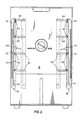
- Those supports in turn comprise a pair of rails 20, 22 which extend generally parallel to each other as shown in Figure 2. Rails 20 and 22 are mounted for sliding movement towards and away from each other on back frame 16, as will be described hereinafter.
- a lower buffer tank 26 is mounted on plate assembly 40 with the latter immersed, as shown in Figures 1 and 4, and an upper buffer tank 36 is mounted at the upper end.
- Both the lower and upper buffer tanks are constructed and mounted substantially as described for US-A-4 828 669 - that is, they clamp on to the front of the gel plate assembly 40 by clamping against rails 20 and 22. Accordingly, few details need be described here.
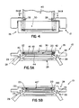
- Clamps 28 are spring biased at 29, as shown in Figure 5A, to press gel plate assembly 40 against rails 20 and 22. The rails are inserted into the box portion 30 of buffer tank 26.
- Rails 20 and 22, as shown more clearly in Figure 2, preferably have a bottom shoulder 32 constructed as described in US-A-4 828 669 to hold gel plate assembly 40.
- Shoulder 32 provides a front surface 34 which protrudes in front of plate assembly 40 to create a pocket which holds and supports the bottom edge 38 of that assembly 40.
- the rails can have any convenient cross-sectional shape.
- An L-shape is preferred, as shown in Figure 5A, wherein the front leg 42 of the rail provides a front surface for contact and support of gel plate assembly 40.
- the opposite, rear surface of leg 42 is used for the clamp which holds upper buffer tank 36 in place (not shown), as described in US-A-4 868 669.
- any convenient gel plate assembly can be used, which, as a minimum, provides a front glass sheet 44, a rear glass sheet 46, a spacer between them at the outside edges (not shown), and a gel 48 coated between the sheets.
- a thermally-conducting sheet such as a metal plate, is applied (not shown) to the back of sheet 46 to allow for better distribution of heat which builds up in the gel.
- means are provided for varying the width of the support, that is, the spacing between rails 20 and 22.
- the construction is such as to allow adjustment in the width without dismantling_the rails, unlike the prior art device.
- rails 20 and 22 are carried by elongated holders 50 and 52, which slide across the front surface 54 of frame 16.
- Holders 50 and 52 in turn have studs or screws 60 projecting rearwardly from the holders, through horizontally extending slots 62, 64, in frame 16. Those slots are spaced vertically along frame 16, and extend only a fraction of the width of frame 16.
- the opposite ends 68 of screws or studs 60 are affixed to two separate control plates 70, 72, as shown in Figure 3, so that frame 16 is sandwiched between holders 50, 52 and plates 70, 72.
- control plates 70, 72 preferably overlap at their corners 74, 76, which overlie the general center 78 of frame 16.
- Horizontal slots 80, 82 extend partway from corners 74 and 76 and in turn overlap each other. Slots 80 and 82 allow control plates 70 and 72 to slide past a control shaft 86 which is rotatably mounted at center 78.
- Attached to shaft 86 behind frame 16 is a drive member disc 90, and to shaft 86 in front of frame 16 a handle 92, as shown in Figure 2.
- Drive disc 90 has mounted to it ( Figure 3) at off-center locations 94 and 96, two drive members in the form of flexible rods 100 and 102.
- One end of each of rods 100 and 102 is affixed to disc 90 at locations 94 and 96, and the other end 110 of each rod is operatively connected to a rail 20 or 22, respectively, by reason of its attachment to control plate 70 or 72.
- a maximum width gel plate assembly 40 is illustrated in place with buffer tank 26 in Figure 5A, whereas a minimum width gel plate assembly 40 is illustrated with the same buffer tank 26 in Figure 5B.
- the change occurs, in the direction indicated by arrows 130, without once removing the gel plate support (rails 20 or 22) from device 10.
- useful widths of gel plate assembly 40 can include 21 and 38cm, and any variation in between, for example.
- device 10A is constructed exactly as described above, so that rails 20A and 22A are connected, via their holders and studs (not shown) to control plates 70A and 72A, driven by control disc 90A mounted on shaft 86A, as before.
- control plates 70A and 72A are generally rectangular and have no slots. Instead, they slide between backing members 200, 202 affixed to frame 16A.
- the flexible rods are replaced by a rack gear 210, 212 on each of plates 70A and 72A, which engage a pinion gear 220 on disk 90A.
- Rotation of disc 90A produces a longitudinal movement, in the direction of arrows 230, of control plates 70A, 72A to achieve movement of rails 20A and 22A, for width variation.
Landscapes
- Health & Medical Sciences (AREA)
- Life Sciences & Earth Sciences (AREA)
- Molecular Biology (AREA)
- Chemical & Material Sciences (AREA)
- Chemical Kinetics & Catalysis (AREA)
- Electrochemistry (AREA)
- Physics & Mathematics (AREA)
- Analytical Chemistry (AREA)
- Biochemistry (AREA)
- General Health & Medical Sciences (AREA)
- General Physics & Mathematics (AREA)
- Immunology (AREA)
- Pathology (AREA)
- Investigating Or Analysing Biological Materials (AREA)
- Devices For Use In Laboratory Experiments (AREA)
- Apparatus Associated With Microorganisms And Enzymes (AREA)
- Electrochromic Elements, Electrophoresis, Or Variable Reflection Or Absorption Elements (AREA)
- Devices For Indicating Variable Information By Combining Individual Elements (AREA)
- Sampling And Sample Adjustment (AREA)
Applications Claiming Priority (2)
| Application Number | Priority Date | Filing Date | Title |
|---|---|---|---|
| US534578 | 1990-06-06 | ||
| US07/534,578 US5043051A (en) | 1990-06-06 | 1990-06-06 | Variable width electrophoresis device |
Publications (2)
| Publication Number | Publication Date |
|---|---|
| EP0460746A1 true EP0460746A1 (fr) | 1991-12-11 |
| EP0460746B1 EP0460746B1 (fr) | 1995-12-06 |
Family
ID=24130659
Family Applications (1)
| Application Number | Title | Priority Date | Filing Date |
|---|---|---|---|
| EP91201328A Expired - Lifetime EP0460746B1 (fr) | 1990-06-06 | 1991-05-31 | Appareils d'électrophorèse |
Country Status (8)
| Country | Link |
|---|---|
| US (1) | US5043051A (fr) |
| EP (1) | EP0460746B1 (fr) |
| JP (1) | JPH04232455A (fr) |
| AU (1) | AU631100B2 (fr) |
| CA (1) | CA2042690A1 (fr) |
| DE (1) | DE69115128T2 (fr) |
| DK (1) | DK0460746T3 (fr) |
| IL (1) | IL98379A (fr) |
Families Citing this family (3)
| Publication number | Priority date | Publication date | Assignee | Title |
|---|---|---|---|---|
| US5360523A (en) * | 1984-03-29 | 1994-11-01 | Li-Cor, Inc. | DNA sequencing |
| US6004446A (en) * | 1984-03-29 | 1999-12-21 | Li-Cor, Inc. | DNA Sequencing |
| EP0684468A3 (fr) * | 1994-05-27 | 1997-03-26 | Eastman Kodak Co | Appareil d'électrophorèse avec structure anti-condensation. |
Citations (3)
| Publication number | Priority date | Publication date | Assignee | Title |
|---|---|---|---|---|
| FR1343548A (fr) * | 1961-08-07 | 1963-11-22 | Ceskoslovenska Akademie Ved | Dispositif pour l'électrophorèse sur papier |
| US3290240A (en) * | 1962-03-14 | 1966-12-06 | Edward J Neren | Vertical electrophoresis apparatus with adjustable media tube |
| US4828669A (en) * | 1988-04-28 | 1989-05-09 | Eastman Kodak Company | Electrophoresis device with removable buffer tank |
Family Cites Families (1)
| Publication number | Priority date | Publication date | Assignee | Title |
|---|---|---|---|---|
| US4518476A (en) * | 1984-04-17 | 1985-05-21 | Bio-Rad Laboratories, Inc. | End clamp for gel slab plate assembly |
-
1990
- 1990-06-06 US US07/534,578 patent/US5043051A/en not_active Expired - Fee Related
-
1991
- 1991-05-15 CA CA002042690A patent/CA2042690A1/fr not_active Abandoned
- 1991-05-15 AU AU77035/91A patent/AU631100B2/en not_active Ceased
- 1991-05-31 EP EP91201328A patent/EP0460746B1/fr not_active Expired - Lifetime
- 1991-05-31 DE DE69115128T patent/DE69115128T2/de not_active Expired - Fee Related
- 1991-05-31 DK DK91201328.1T patent/DK0460746T3/da active
- 1991-06-05 JP JP3134122A patent/JPH04232455A/ja active Pending
- 1991-06-05 IL IL9837991A patent/IL98379A/en not_active IP Right Cessation
Patent Citations (3)
| Publication number | Priority date | Publication date | Assignee | Title |
|---|---|---|---|---|
| FR1343548A (fr) * | 1961-08-07 | 1963-11-22 | Ceskoslovenska Akademie Ved | Dispositif pour l'électrophorèse sur papier |
| US3290240A (en) * | 1962-03-14 | 1966-12-06 | Edward J Neren | Vertical electrophoresis apparatus with adjustable media tube |
| US4828669A (en) * | 1988-04-28 | 1989-05-09 | Eastman Kodak Company | Electrophoresis device with removable buffer tank |
Also Published As
| Publication number | Publication date |
|---|---|
| DK0460746T3 (da) | 1996-01-02 |
| IL98379A0 (en) | 1992-07-15 |
| US5043051A (en) | 1991-08-27 |
| AU631100B2 (en) | 1992-11-12 |
| AU7703591A (en) | 1991-12-12 |
| EP0460746B1 (fr) | 1995-12-06 |
| CA2042690A1 (fr) | 1991-12-07 |
| DE69115128T2 (de) | 1996-06-20 |
| DE69115128D1 (de) | 1996-01-18 |
| IL98379A (en) | 1995-10-31 |
| JPH04232455A (ja) | 1992-08-20 |
Similar Documents
| Publication | Publication Date | Title |
|---|---|---|
| EP0234836B1 (fr) | Dispositif d'électrophorèse à gel gradué à champ pulsé | |
| EP0460746B1 (fr) | Appareils d'électrophorèse | |
| US7213430B2 (en) | Tube bending machine and its right and/or left bending device | |
| US5423603A (en) | High/low profile rocker | |
| EP1671181B1 (fr) | Cabine photographique transportable | |
| KR860006758A (ko) | 광고판 및 루프 광고(loop sign)가 결합된 교체 자재한 복합 광고 조립체 | |
| TW262531B (en) | Balanced drive for orbital tube whip rod heat exchanger | |
| CN219552360U (zh) | 一种液相色谱进样装置 | |
| DE68921213T2 (de) | Halteanordnung für glasbiegungsofen. | |
| CN213433397U (zh) | 组装设备 | |
| CN114110377A (zh) | 一种调节装置 | |
| EP0745442B1 (fr) | Appareil pour plier de la tôle | |
| CN219924212U (zh) | 一种自动的u形折弯机 | |
| CN217459583U (zh) | 一种棱镜镀膜用装载夹具 | |
| CN114433732A (zh) | 一种铝合金型材制造用可调节折弯装置 | |
| CN217954769U (zh) | 一种光学实验用滤光片固定装置 | |
| ATE145536T1 (de) | Gerät zum braten von tieren oder grossen fleischstücken | |
| CN221386513U (zh) | 一种用于蛋白层析系统的层析柱支架 | |
| SU1326519A2 (ru) | Устройство дл разделени листов ферромагнитного материала | |
| CN220762295U (zh) | 一种亚克力板材圆弧加工用固定装置 | |
| CN218699493U (zh) | 一种鼻托条料的切断装置 | |
| GB2191388A (en) | Separating potato flesh from potato half | |
| CN214642804U (zh) | 一种板材外壁处理夹持架 | |
| CN213728703U (zh) | 一种壳体折弯装置 | |
| SU812589A1 (ru) | Устройство дл формовани погру-жЕНиЕМ издЕлий из пОлиМЕРНыХ MATE-РиАлОВ |
Legal Events
| Date | Code | Title | Description |
|---|---|---|---|
| PUAI | Public reference made under article 153(3) epc to a published international application that has entered the european phase |
Free format text: ORIGINAL CODE: 0009012 |
|
| AK | Designated contracting states |
Kind code of ref document: A1 Designated state(s): CH DE DK FR GB IT LI SE |
|
| 17P | Request for examination filed |
Effective date: 19920504 |
|
| 17Q | First examination report despatched |
Effective date: 19930909 |
|
| GRAA | (expected) grant |
Free format text: ORIGINAL CODE: 0009210 |
|
| ITF | It: translation for a ep patent filed | ||
| AK | Designated contracting states |
Kind code of ref document: B1 Designated state(s): CH DE DK FR GB IT LI SE |
|
| REG | Reference to a national code |
Ref country code: DK Ref legal event code: T3 |
|
| REF | Corresponds to: |
Ref document number: 69115128 Country of ref document: DE Date of ref document: 19960118 |
|
| REG | Reference to a national code |
Ref country code: CH Ref legal event code: NV Representative=s name: KIRKER & CIE SA |
|
| PGFP | Annual fee paid to national office [announced via postgrant information from national office to epo] |
Ref country code: DK Payment date: 19960318 Year of fee payment: 6 |
|
| ET | Fr: translation filed | ||
| PGFP | Annual fee paid to national office [announced via postgrant information from national office to epo] |
Ref country code: GB Payment date: 19960412 Year of fee payment: 6 |
|
| PGFP | Annual fee paid to national office [announced via postgrant information from national office to epo] |
Ref country code: SE Payment date: 19960418 Year of fee payment: 6 |
|
| PGFP | Annual fee paid to national office [announced via postgrant information from national office to epo] |
Ref country code: FR Payment date: 19960515 Year of fee payment: 6 |
|
| PGFP | Annual fee paid to national office [announced via postgrant information from national office to epo] |
Ref country code: DE Payment date: 19960531 Year of fee payment: 6 |
|
| PGFP | Annual fee paid to national office [announced via postgrant information from national office to epo] |
Ref country code: CH Payment date: 19960703 Year of fee payment: 6 |
|
| PLBE | No opposition filed within time limit |
Free format text: ORIGINAL CODE: 0009261 |
|
| STAA | Information on the status of an ep patent application or granted ep patent |
Free format text: STATUS: NO OPPOSITION FILED WITHIN TIME LIMIT |
|
| 26N | No opposition filed | ||
| PG25 | Lapsed in a contracting state [announced via postgrant information from national office to epo] |
Ref country code: LI Free format text: LAPSE BECAUSE OF NON-PAYMENT OF DUE FEES Effective date: 19970531 Ref country code: GB Effective date: 19970531 Ref country code: DK Free format text: LAPSE BECAUSE OF NON-PAYMENT OF DUE FEES Effective date: 19970531 Ref country code: CH Free format text: LAPSE BECAUSE OF NON-PAYMENT OF DUE FEES Effective date: 19970531 |
|
| REG | Reference to a national code |
Ref country code: DK Ref legal event code: EBP |
|
| PG25 | Lapsed in a contracting state [announced via postgrant information from national office to epo] |
Ref country code: SE Effective date: 19970601 |
|
| REG | Reference to a national code |
Ref country code: CH Ref legal event code: PL |
|
| GBPC | Gb: european patent ceased through non-payment of renewal fee |
Effective date: 19970531 |
|
| PG25 | Lapsed in a contracting state [announced via postgrant information from national office to epo] |
Ref country code: FR Free format text: LAPSE BECAUSE OF NON-PAYMENT OF DUE FEES Effective date: 19980130 |
|
| PG25 | Lapsed in a contracting state [announced via postgrant information from national office to epo] |
Ref country code: DE Free format text: LAPSE BECAUSE OF NON-PAYMENT OF DUE FEES Effective date: 19980203 |
|
| EUG | Se: european patent has lapsed |
Ref document number: 91201328.1 |
|
| REG | Reference to a national code |
Ref country code: FR Ref legal event code: ST |
|
| PG25 | Lapsed in a contracting state [announced via postgrant information from national office to epo] |
Ref country code: IT Free format text: LAPSE BECAUSE OF NON-PAYMENT OF DUE FEES;WARNING: LAPSES OF ITALIAN PATENTS WITH EFFECTIVE DATE BEFORE 2007 MAY HAVE OCCURRED AT ANY TIME BEFORE 2007. THE CORRECT EFFECTIVE DATE MAY BE DIFFERENT FROM THE ONE RECORDED. Effective date: 20050531 |