EP0460755A1 - Hydraulische Pfahlramme - Google Patents
Hydraulische Pfahlramme Download PDFInfo
- Publication number
- EP0460755A1 EP0460755A1 EP91201351A EP91201351A EP0460755A1 EP 0460755 A1 EP0460755 A1 EP 0460755A1 EP 91201351 A EP91201351 A EP 91201351A EP 91201351 A EP91201351 A EP 91201351A EP 0460755 A1 EP0460755 A1 EP 0460755A1
- Authority
- EP
- European Patent Office
- Prior art keywords
- pressure
- control unit
- conduit
- valve
- cylinder
- Prior art date
- Legal status (The legal status is an assumption and is not a legal conclusion. Google has not performed a legal analysis and makes no representation as to the accuracy of the status listed.)
- Granted
Links
- 230000008878 coupling Effects 0.000 claims description 5
- 238000010168 coupling process Methods 0.000 claims description 5
- 238000005859 coupling reaction Methods 0.000 claims description 5
- 230000001419 dependent effect Effects 0.000 claims 2
- 238000000034 method Methods 0.000 abstract description 5
- 230000008054 signal transmission Effects 0.000 abstract description 5
- 238000009434 installation Methods 0.000 abstract description 3
- 230000015556 catabolic process Effects 0.000 abstract description 2
- 239000007788 liquid Substances 0.000 description 9
- 238000010586 diagram Methods 0.000 description 2
- 238000013016 damping Methods 0.000 description 1
- 230000000694 effects Effects 0.000 description 1
- 239000013013 elastic material Substances 0.000 description 1
- 230000007935 neutral effect Effects 0.000 description 1
- 230000035939 shock Effects 0.000 description 1
- 238000003466 welding Methods 0.000 description 1
Images

Classifications
-
- E—FIXED CONSTRUCTIONS
- E02—HYDRAULIC ENGINEERING; FOUNDATIONS; SOIL SHIFTING
- E02D—FOUNDATIONS; EXCAVATIONS; EMBANKMENTS; UNDERGROUND OR UNDERWATER STRUCTURES
- E02D7/00—Methods or apparatus for placing sheet pile bulkheads, piles, mouldpipes, or other moulds
- E02D7/02—Placing by driving
- E02D7/06—Power-driven drivers
- E02D7/10—Power-driven drivers with pressure-actuated hammer, i.e. the pressure fluid acting directly on the hammer structure
Definitions
- the present invention relates to a hydraulic control device for the falling weight of a pile driving installation, comprising:
- This known hydraulic control device is arranged for the greater part in the vicinity of the hydraulic lifting cylinder for the falling weight or striker weight, and therefore in the vicinity of the striker weight. Since the striker weight is initially situated high in the piling frame and slowly moves downward during further driving of the pile into the ground, the hydraulic cylinder for driving the striker weight will likewise move downward during the course of the pile driving process.
- control device When, as with this known device, the control device is situated substantially in the vicinity of the striker weight this control device will likewise be slowly moved downward during the pile driving process.
- This control device is moreover subjected to the vibrations and shocks usually prevailing in the upper part of the piling frame as a result of the pile driving.
- the object of the present invention is to provide a control device wherein the above stated drawbacks are avoided.
- the hydraulic control device is distinguished in that the control unit is arranged such that when pressure is applied to the pressure conduit the pressure in the pressure conduit lifts the weight and, when the pressure in the pressure conduit falls away, the falling weight moves downward.
- control unit present at the top of the piling frame thus reacts directly to the pressure in the pressure conduit, making use of this the pile-driving process can be controlled from below without transferring signals via extra means for signal transmission such as electrical cables.
- control unit comprises a valve connected to the lifting side of the cylinder, which valve is closed when pressure is applied to the pressure conduit and which opens when the pressure in the pressure conduit falls away.
- Fig. 1 shows a piling frame 1 which is secured by means of wires 2.
- the piling frame rests on a ground plate 3 on which is mounted an aggregate 4.
- a carrier 5 Arranged in the top of the piling frame is a carrier 5 which is movable along the piling frame by means of means not shown here and on which a control box 6 is arranged.
- a hydraulic cylinder 7 wherein a piston 8 is arranged which is connected to the striker weight 11 by means of a piston rod 9 and a coupling 10.
- the control member 13 which takes a portable form, is connected to the aggregate 4 by means of a cable 14.
- the aggregate 4 is further connected to the control unit 6 by means of both a pressure conduit 15 and a pressureless conduit 16.
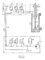
- the diagram of fig. 2 shows how a pump 17 is incorporated in the aggregate 4, the discharge side of which pump is connected to an expansion tank 18.
- This discharge side of the pump is further connected to a pressure control valve 19, which is also electrically controllable and then acts as short circuit valve, and an electrically controllable valve 20.
- the outlet side of the valve 19 is connected to a reservoir 21, while the outflow side of the valve 20 is connected to the pressure carrying conduit 15 and to the feed side of a second electrical valve 22.
- the discharge side of the second electrical valve 22 is connected via a channel to the reservoir 21, as is the pressureless channel 16.
- the control unit 6 arranged in the vicinity of the cylinder 7 comprises a first automatic valve 23, the inflow side of which is connected to the pressure conduit 15 and the outflow side of which is connected to the lifting side of the cylinder 7, that is, the chamber of the cylinder 7 which is situated under the piston 8.
- the outflow side of the third valve 23 is further connected to a second automatic valve 24 and to the inflow side of a second pressure control valve 25.
- the outflow side of both the second automatic valve 24 and the second pressure control valve 25 is connected to the descent side of the hydraulic cylinder, that is, the chamber located above the piston 8. This side is also connected to a second expansion tank 26 which is otherwise connected to the pressureless conduit 16.
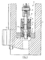
- fig. 3 shows how the piston rod 9 is connected to the striker weight 11 by means of a coupling 10.
- a bearing 27 Arranged on the underside of the piston rod 9 is a bearing 27 through which extends a pin 28.
- the pin 28 also extends through a sleeve 29 arranged concentrically relative to the underside of the piston rod 9, so that the sleeve 29 is rotatable round a horizontal axis relative to the piston rod 9.
- a rod 30 Arranged on the underside of the sleeve is a rod 30 which is connected to the sleeve 29 for example by welding.
- the rod is provided with a number of shoulders 31, 32, 33.
- the bottom part of the rod 30 extends inside a sleeve 34 which is closed off on both sides by covers 35, 36 through which the rod 30 extends.
- the space between the rod 30 and the sleeve 34 which is enclosed by the covers 35, 36 is occupied by a slightly elastic mass 38.
- This mass 38 transfers the forces acting in the vertical direction between the rod 30 and the sleeve 34 so that a slightly elastic coupling is obtained, wherein due to the properties of the slightly elastic material a certain damping is obtained which has the effect of improving the service life of the various components.
- the sleeve 37 is further connected on its underside to the striker weight 11. On the left in fig. 3 can also be seen a part of the guiding of the striker weight 11. This guiding does not form any part of the present application and will not be discussed further.
- a pressure will first have to be built up in the expansion tank 18 by means of the pump 17.
- the pump 17 obtains its hydraulic liquid from the reservoir 21.
- the pressure control valve 19 is open so that through the throttle action of this valve the pressure built up by the pump 17 is throttled and only a small amount of liquid flows through the valve to the reservoir 21.
- valves 20 and 22 are here closed. No pressure is thus created on the pressure conduit 15, so that the piston 8 remains in the cylinder 7 in its lowest position.
- the pressure control valve 25 otherwise serves the purpose of not allowing the pressure in the bottom chamber of the cylinder 7 to rise excessively; when a determined limit value is exceeded the pressure control valve 25 will partially open so that the pressure inside the cylinder 7 is compensated.
Landscapes
- Engineering & Computer Science (AREA)
- General Engineering & Computer Science (AREA)
- General Life Sciences & Earth Sciences (AREA)
- Mining & Mineral Resources (AREA)
- Paleontology (AREA)
- Civil Engineering (AREA)
- Life Sciences & Earth Sciences (AREA)
- Structural Engineering (AREA)
- Placing Or Removing Of Piles Or Sheet Piles, Or Accessories Thereof (AREA)
- Fluid-Pressure Circuits (AREA)
- Silver Salt Photography Or Processing Solution Therefor (AREA)
- On-Site Construction Work That Accompanies The Preparation And Application Of Concrete (AREA)
- Forklifts And Lifting Vehicles (AREA)
Applications Claiming Priority (2)
| Application Number | Priority Date | Filing Date | Title |
|---|---|---|---|
| NL9001284 | 1990-06-07 | ||
| NL9001284A NL9001284A (nl) | 1990-06-07 | 1990-06-07 | Hydraulische hei-inrichting. |
Publications (2)
| Publication Number | Publication Date |
|---|---|
| EP0460755A1 true EP0460755A1 (de) | 1991-12-11 |
| EP0460755B1 EP0460755B1 (de) | 1994-09-28 |
Family
ID=19857201
Family Applications (1)
| Application Number | Title | Priority Date | Filing Date |
|---|---|---|---|
| EP91201351A Expired - Lifetime EP0460755B1 (de) | 1990-06-07 | 1991-06-03 | Hydraulische Pfahlramme |
Country Status (6)
| Country | Link |
|---|---|
| EP (1) | EP0460755B1 (de) |
| AT (1) | ATE112346T1 (de) |
| DE (1) | DE69104268T2 (de) |
| DK (1) | DK0460755T3 (de) |
| ES (1) | ES2061159T3 (de) |
| NL (1) | NL9001284A (de) |
Cited By (3)
| Publication number | Priority date | Publication date | Assignee | Title |
|---|---|---|---|---|
| EP0675233A4 (de) * | 1992-08-19 | 1996-01-31 | Aktsionernoe Obschestvo Zakryt | Hydraulische pfahlramme. |
| CN103846904A (zh) * | 2012-11-30 | 2014-06-11 | 中国科学院沈阳自动化研究所 | 一种用于控制水下液压机械手的伺服阀箱 |
| CN115450213A (zh) * | 2021-11-08 | 2022-12-09 | 湖北金满赢建设有限公司 | 一种具有防倾倒保护的自走式打桩机 |
Citations (2)
| Publication number | Priority date | Publication date | Assignee | Title |
|---|---|---|---|---|
| GB847780A (en) * | 1958-04-24 | 1960-09-14 | Maurice Auberger | Hydraulic control for battering rams and the like |
| US3446293A (en) * | 1966-12-28 | 1969-05-27 | American Drilling & Boring Co | Pile driver |
-
1990
- 1990-06-07 NL NL9001284A patent/NL9001284A/nl not_active Application Discontinuation
-
1991
- 1991-06-03 DE DE69104268T patent/DE69104268T2/de not_active Expired - Fee Related
- 1991-06-03 ES ES91201351T patent/ES2061159T3/es not_active Expired - Lifetime
- 1991-06-03 AT AT91201351T patent/ATE112346T1/de not_active IP Right Cessation
- 1991-06-03 DK DK91201351.3T patent/DK0460755T3/da active
- 1991-06-03 EP EP91201351A patent/EP0460755B1/de not_active Expired - Lifetime
Patent Citations (2)
| Publication number | Priority date | Publication date | Assignee | Title |
|---|---|---|---|---|
| GB847780A (en) * | 1958-04-24 | 1960-09-14 | Maurice Auberger | Hydraulic control for battering rams and the like |
| US3446293A (en) * | 1966-12-28 | 1969-05-27 | American Drilling & Boring Co | Pile driver |
Non-Patent Citations (1)
| Title |
|---|
| PATENT ABSTRACTS OF JAPAN vol. 10, no. 40 (M-454)(2097) February 18, 1986 & JP-A-60 192 026 (HITACHI ) September 30, 1985 * |
Cited By (3)
| Publication number | Priority date | Publication date | Assignee | Title |
|---|---|---|---|---|
| EP0675233A4 (de) * | 1992-08-19 | 1996-01-31 | Aktsionernoe Obschestvo Zakryt | Hydraulische pfahlramme. |
| CN103846904A (zh) * | 2012-11-30 | 2014-06-11 | 中国科学院沈阳自动化研究所 | 一种用于控制水下液压机械手的伺服阀箱 |
| CN115450213A (zh) * | 2021-11-08 | 2022-12-09 | 湖北金满赢建设有限公司 | 一种具有防倾倒保护的自走式打桩机 |
Also Published As
| Publication number | Publication date |
|---|---|
| DE69104268D1 (de) | 1994-11-03 |
| DE69104268T2 (de) | 1995-02-16 |
| NL9001284A (nl) | 1992-01-02 |
| ES2061159T3 (es) | 1994-12-01 |
| ATE112346T1 (de) | 1994-10-15 |
| EP0460755B1 (de) | 1994-09-28 |
| DK0460755T3 (da) | 1994-11-07 |
Similar Documents
| Publication | Publication Date | Title |
|---|---|---|
| US4479550A (en) | Submerging ramming arrangement | |
| EP2321472B1 (de) | Verfahren und vorrichtung zum pfahleintreiben unter wasser | |
| EP0947294B1 (de) | Hydraulisch betriebene Schlagvorrichtung | |
| US5256003A (en) | Method for automatically driving gravel drain piles and execution apparatus therefor | |
| EP0095801A1 (de) | Hydraulische Pfahlrammanlage | |
| JPS6365773B2 (de) | ||
| EP1630303B1 (de) | Hydraulische antriebsvorrichtung | |
| EP0460755B1 (de) | Hydraulische Pfahlramme | |
| CA2028917C (en) | Floating dredger | |
| EP2262975B1 (de) | Schütteldeckeinstellungsvorrichtung | |
| GB1594452A (en) | Impact apparatus | |
| US3442338A (en) | Hydraulic circuit for mobile hydraulic hammer | |
| US4802538A (en) | Piling hammer | |
| US3949496A (en) | Wave compensating system for suction dredgers | |
| EP0567698B1 (de) | Eingangsglied | |
| EP1828486B1 (de) | Fallgewichts-bodenverdichtungsvorrichtung | |
| SU1605046A1 (ru) | Система защиты гидропривода | |
| SU1553631A1 (ru) | Бульдозер | |
| SU1216301A1 (ru) | Фронтальный погрузчик | |
| SU1074941A2 (ru) | Вибротрамбовка | |
| SU729309A1 (ru) | Копровое оборудование | |
| JPS6329051B2 (de) | ||
| JPH10331157A (ja) | 油圧ドロップハンマ | |
| JPH0324547B2 (de) | ||
| ES2066646A2 (es) | Equipo de hinca de pilotes. |
Legal Events
| Date | Code | Title | Description |
|---|---|---|---|
| PUAI | Public reference made under article 153(3) epc to a published international application that has entered the european phase |
Free format text: ORIGINAL CODE: 0009012 |
|
| AK | Designated contracting states |
Kind code of ref document: A1 Designated state(s): AT BE CH DE DK ES FR GB GR IT LI LU NL SE |
|
| 17P | Request for examination filed |
Effective date: 19920415 |
|
| 17Q | First examination report despatched |
Effective date: 19920601 |
|
| GRAA | (expected) grant |
Free format text: ORIGINAL CODE: 0009210 |
|
| AK | Designated contracting states |
Kind code of ref document: B1 Designated state(s): AT BE CH DE DK ES FR GB GR IT LI LU NL SE |
|
| REF | Corresponds to: |
Ref document number: 112346 Country of ref document: AT Date of ref document: 19941015 Kind code of ref document: T |
|
| REF | Corresponds to: |
Ref document number: 69104268 Country of ref document: DE Date of ref document: 19941103 |
|
| REG | Reference to a national code |
Ref country code: DK Ref legal event code: T3 |
|
| REG | Reference to a national code |
Ref country code: ES Ref legal event code: FG2A Ref document number: 2061159 Country of ref document: ES Kind code of ref document: T3 |
|
| ET | Fr: translation filed | ||
| ITF | It: translation for a ep patent filed | ||
| EAL | Se: european patent in force in sweden |
Ref document number: 91201351.3 |
|
| REG | Reference to a national code |
Ref country code: GR Ref legal event code: FG4A Free format text: 3014456 |
|
| PGFP | Annual fee paid to national office [announced via postgrant information from national office to epo] |
Ref country code: NL Payment date: 19950629 Year of fee payment: 5 |
|
| PGFP | Annual fee paid to national office [announced via postgrant information from national office to epo] |
Ref country code: SE Payment date: 19950630 Year of fee payment: 5 Ref country code: ES Payment date: 19950630 Year of fee payment: 5 Ref country code: DE Payment date: 19950630 Year of fee payment: 5 Ref country code: AT Payment date: 19950630 Year of fee payment: 5 |
|
| PGFP | Annual fee paid to national office [announced via postgrant information from national office to epo] |
Ref country code: GB Payment date: 19950710 Year of fee payment: 5 |
|
| PGFP | Annual fee paid to national office [announced via postgrant information from national office to epo] |
Ref country code: GR Payment date: 19950718 Year of fee payment: 5 Ref country code: BE Payment date: 19950718 Year of fee payment: 5 |
|
| PGFP | Annual fee paid to national office [announced via postgrant information from national office to epo] |
Ref country code: FR Payment date: 19950728 Year of fee payment: 5 |
|
| PLBE | No opposition filed within time limit |
Free format text: ORIGINAL CODE: 0009261 |
|
| STAA | Information on the status of an ep patent application or granted ep patent |
Free format text: STATUS: NO OPPOSITION FILED WITHIN TIME LIMIT |
|
| PGFP | Annual fee paid to national office [announced via postgrant information from national office to epo] |
Ref country code: DK Payment date: 19950731 Year of fee payment: 5 |
|
| PGFP | Annual fee paid to national office [announced via postgrant information from national office to epo] |
Ref country code: CH Payment date: 19950807 Year of fee payment: 5 |
|
| PGFP | Annual fee paid to national office [announced via postgrant information from national office to epo] |
Ref country code: LU Payment date: 19950901 Year of fee payment: 5 |
|
| 26N | No opposition filed | ||
| PG25 | Lapsed in a contracting state [announced via postgrant information from national office to epo] |
Ref country code: LU Free format text: LAPSE BECAUSE OF NON-PAYMENT OF DUE FEES Effective date: 19960603 Ref country code: GB Effective date: 19960603 Ref country code: DK Effective date: 19960603 Ref country code: AT Effective date: 19960603 |
|
| REG | Reference to a national code |
Ref country code: DK Ref legal event code: EBP |
|
| PG25 | Lapsed in a contracting state [announced via postgrant information from national office to epo] |
Ref country code: SE Effective date: 19960604 Ref country code: ES Free format text: LAPSE BECAUSE OF EXPIRATION OF PROTECTION Effective date: 19960604 |
|
| PG25 | Lapsed in a contracting state [announced via postgrant information from national office to epo] |
Ref country code: LI Effective date: 19960630 Ref country code: CH Effective date: 19960630 Ref country code: BE Effective date: 19960630 |
|
| BERE | Be: lapsed |
Owner name: HOLDING A. BAARS AZN B.V. Effective date: 19960630 |
|
| PG25 | Lapsed in a contracting state [announced via postgrant information from national office to epo] |
Ref country code: GR Free format text: THE PATENT HAS BEEN ANNULLED BY A DECISION OF A NATIONAL AUTHORITY Effective date: 19961231 |
|
| PG25 | Lapsed in a contracting state [announced via postgrant information from national office to epo] |
Ref country code: NL Effective date: 19970101 |
|
| GBPC | Gb: european patent ceased through non-payment of renewal fee |
Effective date: 19960603 |
|
| REG | Reference to a national code |
Ref country code: GR Ref legal event code: MM2A Free format text: 3014456 |
|
| REG | Reference to a national code |
Ref country code: CH Ref legal event code: PL |
|
| PG25 | Lapsed in a contracting state [announced via postgrant information from national office to epo] |
Ref country code: FR Effective date: 19970228 |
|
| PG25 | Lapsed in a contracting state [announced via postgrant information from national office to epo] |
Ref country code: DE Effective date: 19970301 |
|
| EUG | Se: european patent has lapsed |
Ref document number: 91201351.3 |
|
| NLV4 | Nl: lapsed or anulled due to non-payment of the annual fee |
Effective date: 19970101 |
|
| REG | Reference to a national code |
Ref country code: FR Ref legal event code: ST |
|
| REG | Reference to a national code |
Ref country code: ES Ref legal event code: FD2A Effective date: 19990601 |
|
| PG25 | Lapsed in a contracting state [announced via postgrant information from national office to epo] |
Ref country code: IT Free format text: LAPSE BECAUSE OF NON-PAYMENT OF DUE FEES Effective date: 20050603 |