EP0460761A1 - Hf-Spulensystem in einem Apparat zur Bilderzeugung mittels magnetischer Resonanz - Google Patents
Hf-Spulensystem in einem Apparat zur Bilderzeugung mittels magnetischer Resonanz Download PDFInfo
- Publication number
- EP0460761A1 EP0460761A1 EP91201369A EP91201369A EP0460761A1 EP 0460761 A1 EP0460761 A1 EP 0460761A1 EP 91201369 A EP91201369 A EP 91201369A EP 91201369 A EP91201369 A EP 91201369A EP 0460761 A1 EP0460761 A1 EP 0460761A1
- Authority
- EP
- European Patent Office
- Prior art keywords
- magnetic resonance
- imaging apparatus
- resonance imaging
- frequency
- bandpass filters
- Prior art date
- Legal status (The legal status is an assumption and is not a legal conclusion. Google has not performed a legal analysis and makes no representation as to the accuracy of the status listed.)
- Granted
Links
- 238000002595 magnetic resonance imaging Methods 0.000 title claims abstract description 20
- 238000005259 measurement Methods 0.000 claims abstract description 15
- 238000010276 construction Methods 0.000 abstract 1
- 238000003384 imaging method Methods 0.000 abstract 1
- 230000006978 adaptation Effects 0.000 description 5
- 238000003491 array Methods 0.000 description 3
- 238000010586 diagram Methods 0.000 description 3
- 238000000034 method Methods 0.000 description 3
- 230000004913 activation Effects 0.000 description 2
- 239000013078 crystal Substances 0.000 description 2
- 238000001514 detection method Methods 0.000 description 2
- 230000010354 integration Effects 0.000 description 2
- 239000002131 composite material Substances 0.000 description 1
- 230000009849 deactivation Effects 0.000 description 1
- 230000001419 dependent effect Effects 0.000 description 1
- 230000003993 interaction Effects 0.000 description 1
Images

Classifications
-
- G—PHYSICS
- G01—MEASURING; TESTING
- G01R—MEASURING ELECTRIC VARIABLES; MEASURING MAGNETIC VARIABLES
- G01R33/00—Arrangements or instruments for measuring magnetic variables
- G01R33/20—Arrangements or instruments for measuring magnetic variables involving magnetic resonance
- G01R33/28—Details of apparatus provided for in groups G01R33/44 - G01R33/64
- G01R33/32—Excitation or detection systems, e.g. using radio frequency signals
- G01R33/34—Constructional details, e.g. resonators, specially adapted to MR
- G01R33/341—Constructional details, e.g. resonators, specially adapted to MR comprising surface coils
- G01R33/3415—Constructional details, e.g. resonators, specially adapted to MR comprising surface coils comprising arrays of sub-coils, i.e. phased-array coils with flexible receiver channels
Definitions
- the invention relates to a magnetic resonance imaging apparatus, comprising a magnet for generating a steady magnetic field in a measuring space, a gradient coil system and an rf coil system consisting of several coil elements.
- a magnetic resonance imaging apparatus of this kind is known from WO 89/05115.
- sub-images are formed from measurement signals of each of the coil elements of a surface coil system.
- Sub-images thus formed are subsequently combined so as to form an ultimate image of a region of an object to be examined by way of the rf surface coil system.
- a comparatively low-noise image can be formed of a region by means of such a measuring method.
- the method requires a comparatively complex signal processing device because simultaneous signal processing chains are required for all sub-images and sub-image integration must be performed pixel-by-pixel in order to prevent addition of noise.
- a magnetic resonance imaging apparatus of the kind set forth in accordance with the invention is characterized in that individual coil elements are provided with a frequency bandpass filter adapted to a measurement frequency band of the relevant coil element.
- frequency bands of successive sub-coils are chosen to be consecutive, possibly with a small mutual overlap or spacing.
- Each of the bandpass filters therefore, covers a frequency band of, for example from 1 to 20 kHz, for example for a chosen measurement gradient and main field.
- a practical embodiment of such a consecutive series can be realised, for example by means of a linear array of surface coils where a longitudinal direction of the array extends parallel to the gradient direction of a measurement gradient field to be generated in the measuring space of the apparatus.
- Respective bandpass filters of coil elements in a preferred embodiment are connected to a single signal processing device for forming a combined signal to be sequentially processed. Between individual bandpass filters and coil elements coupled thereto a preamplifier is inserted in order to reduce added noise in a preferred embodiment. Such a preamplifier may also be included between the bandpass filters and the common signal processing device.
- the frequency of the bandpass filter may be adjustable. In that case the minimum frequency or central frequency or, the bandwidth of the frequency band can be adjustable or both.
- an input mixer and an output mixer are added. Both mixers are connected to an auxiliary oscillator in order to form a substantially fixed difference frequency for a varying input frequency.
- the auxiliary oscillator is adjustable notably by means of a control signal which is dependent on a main field strength in a measuring space.
- sub-coils may be constructed so as to overlap one another as surface coils, for example as described in EP 273 484, or as butterfly coils, for example as described in EP 218 290.
- a magnetic resonance imaging apparatus as shown in Fig. 1 comprises a magnet system 2 for generating a steady, uniform magnetic field, a magnet system 4 for generating magnetic gradient fields, and control devices 6 and 8 for the magnet system 2 and the magnet system 4, respectively.
- a magnet coil 10 for generating an rf magnetic alternating field is connected to an rf source 12.
- the coil system 13 is connected to a signal processing device 14.
- the signal processing device 14 is connected to a phase-sensitive rectifier 16 which is connected to a central control device 18.
- the central control device 18 also controls a modulator 20 for the rf source 12, the control device 8 for the gradient coils and a monitor 22 for image display.
- An rf oscillator 24 controls the modulator 20 as well as the phase-sensitive rectifier 16 which processes the measurement signals.
- the transmitter coil 10 being arranged within the magnet systems 2 and 4 and constructed, for example as a bird cage coil as described in EP 213 665, encloses a measuring space 28 which, in the case of a medical diagnostic apparatus, offers adequate space to accommodate patients.
- a steady magnetic field, gradient fields for position selection of slices to be imaged, and a spatially uniform rf alternating field can thus be generated in the measuring space 28.
- a steady magnetic field generated by the steady magnet system 2 is oriented in the axial direction in the present embodiment.
- the gradient magnet system in a magnetic resonance imaging apparatus customarily comprises a coil system for three coordinate directions, activation of said coil system producing gradient fields in each of the three directions so that a point-by-point image of an object can be formed.
- the measurement gradient fields are oriented, for example along the axial axis 30 and in two directions extending transversely thereof.
- the coil system 13 of the present embodiment comprises a linear coil system 31 which includes a plurality of coils which are not separately shown and for which it is assumed for the sake of simplicity that a common axis thereof is directed parallel to an axis coincident with an axial axis 30 of a gradient field to be applied.
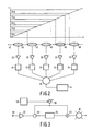
- Individual coils of the linear coil system are connected to a common summing device 36, via preamplifiers 32 and a bandpass filter 34.
- the summing device forms a composite signal which can be applied to the signal processing device 14 for sequential processing.
- the bandpass filters 34 are connected to the control device 6 of the main magnet system 2 for main field adaptation as will be described hereinafter.
- the circuit diagram of Fig. 2 shows a linear coil system 31 comprising five coils 40.
- the coils 40 are preferably surface coils which can be arranged in the described manner and which are situated along a common axis 42 for optimum operation.
- the axis 42 extends parallel to the measurement gradient field direction in the apparatus.
- the measuring coils are thus accommodated in spaces in which different magnetic field strengths prevail. Therefore, even fully identical coils correspond to different frequency ranges.
- the bandpass filters 34 are optimally adapted to these frequency bands, i.e. so that the nominal frequency or the width of each filter in each case corresponds substantially to the frequencies of the associated frequency range.
- the decay curve of the band filters can be rather arbitrarily chosen for as long as no disturbing interaction occurs with neighbouring frequency bands, so that said curve can be adapted to further signal processing.
- Frequency bands of individual bandpass filters have a width of, for example from 1 to 20 kHz and the signal transfer of a filter at the area of overlap amounts to, for example at the most approximately 70% of the maximum signal transfer.
- the bandpass filters are connected to the summing device or multiplexer 36 whereto a signal processing device 44 is connected. This device covers a frequency range which covers the sum of the frequency bands of the bandpass filters.
- the overall frequency range may be equal to a customary measurement bandwidth in a magnetic resonance imaging apparatus. As a result, only minimum adaptations are required in the signal processing device.
- Two of such linear coil arrays may be included in a magnetic resonance imaging apparatus, the common axes thereof being oriented mutual perpendicularly.
- One of the coil elements for example a central element of each of the arrays, may then be a common element.
- Preamplifiers of the coil arrays are then preferably connected to the gradient coil control system for activation and deactivation in dependence on the applied gradient field.
- Fig. 3 shows a band filter frequency adaptation circuit comprising an input mixer 50 and an output mixer 52 wherebetween a filter 54 is connected, for example a crystal filter.
- the input mixer 50 is connected to an input amplifier 32 and the output mixer is connected to a central signal processing device 36.
- An rf source 56 which is fed by a dc voltage supply 58 is also connected to the mixer.
- a resonance signal having a frequency f IN enters via an input terminal 60 and the generator forms a control signal having a frequency f LO
- the frequency f UT of the output signal always remains equal to that of the input signal f IN, regardless of the value of f LO.
- the filter 54 can always operate at a fixed, nominal frequency f IF.
Landscapes
- Physics & Mathematics (AREA)
- Condensed Matter Physics & Semiconductors (AREA)
- General Physics & Mathematics (AREA)
- Magnetic Resonance Imaging Apparatus (AREA)
Applications Claiming Priority (2)
| Application Number | Priority Date | Filing Date | Title |
|---|---|---|---|
| NL9001298A NL9001298A (nl) | 1990-06-08 | 1990-06-08 | Rf spoelenstelsel in magnetisch resonantie apparaat. |
| NL9001298 | 1990-06-08 |
Publications (2)
| Publication Number | Publication Date |
|---|---|
| EP0460761A1 true EP0460761A1 (de) | 1991-12-11 |
| EP0460761B1 EP0460761B1 (de) | 1997-04-09 |
Family
ID=19857212
Family Applications (1)
| Application Number | Title | Priority Date | Filing Date |
|---|---|---|---|
| EP91201369A Expired - Lifetime EP0460761B1 (de) | 1990-06-08 | 1991-06-04 | Hf-Spulensystem in einem Apparat zur Bilderzeugung mittels magnetischer Resonanz |
Country Status (5)
| Country | Link |
|---|---|
| US (1) | US5272437A (de) |
| EP (1) | EP0460761B1 (de) |
| JP (1) | JP3164377B2 (de) |
| DE (1) | DE69125526T2 (de) |
| NL (1) | NL9001298A (de) |
Cited By (5)
| Publication number | Priority date | Publication date | Assignee | Title |
|---|---|---|---|---|
| EP0554584A1 (de) * | 1991-11-29 | 1993-08-11 | Koninklijke Philips Electronics N.V. | Magnetische Resonanzanordnung und Signalkombinationsanordnung |
| DE4412446A1 (de) * | 1994-04-12 | 1995-10-19 | Bruker Medizintech | Verfahren und Vorrichtung zur Erstellung eines NMR-Tomographiebildes |
| EP0467378B1 (de) * | 1990-07-18 | 1998-09-16 | Kabushiki Kaisha Toshiba | NMR-Abbildungssystem mit mehreren Spulen und Filter mit verschiednen Bandbreiten |
| WO2003096051A1 (en) * | 2002-05-13 | 2003-11-20 | Koninklijke Philips Electronics N.V. | Magnetic resonance imaging method |
| WO2009070717A1 (en) * | 2007-11-27 | 2009-06-04 | Kim Jae K | Noise reduction by means of spectral parallelism |
Families Citing this family (5)
| Publication number | Priority date | Publication date | Assignee | Title |
|---|---|---|---|---|
| US7109710B2 (en) * | 2003-10-17 | 2006-09-19 | General Electric Company | Method and apparatus to improve signal-to-noise ratio without compromising field-of-view for simultaneous MR data acquisition by an array of RF coils of an MR scanner |
| DE102008023467B4 (de) * | 2008-05-14 | 2012-06-14 | Siemens Aktiengesellschaft | Anordnung zur Übertragung von Magnetresonanzsignalen |
| US8686725B2 (en) * | 2009-06-29 | 2014-04-01 | General Electric Company | System and apparatus for frequency translation of magnetic resonance (MR) signals |
| DE102010032825B4 (de) * | 2010-07-30 | 2013-01-24 | Siemens Aktiengesellschaft | Magnetresonanzbildgebung mit gezielter Präparation der Magnetisierung |
| CN107797084B (zh) * | 2016-09-06 | 2020-03-06 | 西门子(深圳)磁共振有限公司 | 磁共振信号接收装置、接收线圈通道选择器及磁共振成像系统 |
Citations (8)
| Publication number | Priority date | Publication date | Assignee | Title |
|---|---|---|---|---|
| US4115730A (en) * | 1976-04-14 | 1978-09-19 | National Research Development Corporation | Nuclear magnetic resonance apparatus and methods |
| EP0112663A2 (de) * | 1982-12-17 | 1984-07-04 | Picker International Limited | Magnetische Kernresonanzmethode und Vorrichtung |
| EP0175129A2 (de) * | 1984-08-16 | 1986-03-26 | General Electric Company | Antennenanordnung mit einer Mehrzahl von nichtorthogonalen Oberflächenspulen für Bilderzeugung mittels magnetischer Kernresonanz |
| US4737713A (en) * | 1986-11-26 | 1988-04-12 | Fonar Corporation | Apparatus and method for processing an electrical signal and increasing a signal-to-noise ratio thereof |
| WO1989005115A1 (en) * | 1987-12-07 | 1989-06-15 | General Electric Company | Nuclear magnetic resonance (nmr) imaging with multiple surface coils |
| EP0325351A2 (de) * | 1988-01-19 | 1989-07-26 | The Regents Of The University Of California | Schaltbare Vielfachanordnung von Hochfrequenzspulen mit verschiedenen und überlappenden Blickfeldern der einzelnen Spulen zur Bilderzeugung mittels magnetischer Resonanz |
| EP0347180A2 (de) * | 1988-06-15 | 1989-12-20 | Btg International Limited | Elektrische Oberflächenspulenanordnungen |
| EP0412824A2 (de) * | 1989-08-09 | 1991-02-13 | Kabushiki Kaisha Toshiba | Anordnung zur Bilderzeugung mittels magnetischer Resonanz |
Family Cites Families (10)
| Publication number | Priority date | Publication date | Assignee | Title |
|---|---|---|---|---|
| US4695798A (en) * | 1985-04-22 | 1987-09-22 | The Regents Of The University Of California | Method and apparatus for generating frequency selective pulses for NMR spectroscopy |
| NL8502273A (nl) * | 1985-08-19 | 1987-03-16 | Philips Nv | Magnetisch resonantie apparaat met bird cage r.f. spoel. |
| NL8502612A (nl) * | 1985-09-25 | 1987-04-16 | Philips Nv | Magnetisch resonantie apparaat met ontkoppelende detectie surface spoel. |
| US4943775A (en) * | 1986-11-27 | 1990-07-24 | U.S. Philips Corporation | Magnetic resonance apparatus with uncoupled rf coils |
| NL8603006A (nl) * | 1986-11-27 | 1988-06-16 | Philips Nv | Magnetisch resonantie apparaat met gestapeld oppervlakte spoelenstelsel. |
| US4825162A (en) * | 1987-12-07 | 1989-04-25 | General Electric Company | Nuclear magnetic resonance (NMR) imaging with multiple surface coils |
| US4885541A (en) * | 1988-08-19 | 1989-12-05 | General Electric Company | Apparatus and method for enhanced multiple coil nuclear magnetic resonance (NMR) imaging |
| US4827219A (en) * | 1988-01-07 | 1989-05-02 | The Regents Of The University Of California | Remotely adjustable MRI RF coil impedance matching circuit with mutualy coupled resonators |
| US4947121A (en) * | 1988-08-19 | 1990-08-07 | General Electric Company | Apparatus and method for enhanced multiple coil nuclear magnetic resonance (NMR) imaging |
| US4916418A (en) * | 1989-03-31 | 1990-04-10 | Varian Associates, Inc. | Double tuned bird cage coil |
-
1990
- 1990-06-08 NL NL9001298A patent/NL9001298A/nl not_active Application Discontinuation
-
1991
- 1991-06-04 DE DE69125526T patent/DE69125526T2/de not_active Expired - Fee Related
- 1991-06-04 EP EP91201369A patent/EP0460761B1/de not_active Expired - Lifetime
- 1991-06-05 JP JP13442991A patent/JP3164377B2/ja not_active Expired - Fee Related
- 1991-06-05 US US07/711,472 patent/US5272437A/en not_active Expired - Fee Related
Patent Citations (8)
| Publication number | Priority date | Publication date | Assignee | Title |
|---|---|---|---|---|
| US4115730A (en) * | 1976-04-14 | 1978-09-19 | National Research Development Corporation | Nuclear magnetic resonance apparatus and methods |
| EP0112663A2 (de) * | 1982-12-17 | 1984-07-04 | Picker International Limited | Magnetische Kernresonanzmethode und Vorrichtung |
| EP0175129A2 (de) * | 1984-08-16 | 1986-03-26 | General Electric Company | Antennenanordnung mit einer Mehrzahl von nichtorthogonalen Oberflächenspulen für Bilderzeugung mittels magnetischer Kernresonanz |
| US4737713A (en) * | 1986-11-26 | 1988-04-12 | Fonar Corporation | Apparatus and method for processing an electrical signal and increasing a signal-to-noise ratio thereof |
| WO1989005115A1 (en) * | 1987-12-07 | 1989-06-15 | General Electric Company | Nuclear magnetic resonance (nmr) imaging with multiple surface coils |
| EP0325351A2 (de) * | 1988-01-19 | 1989-07-26 | The Regents Of The University Of California | Schaltbare Vielfachanordnung von Hochfrequenzspulen mit verschiedenen und überlappenden Blickfeldern der einzelnen Spulen zur Bilderzeugung mittels magnetischer Resonanz |
| EP0347180A2 (de) * | 1988-06-15 | 1989-12-20 | Btg International Limited | Elektrische Oberflächenspulenanordnungen |
| EP0412824A2 (de) * | 1989-08-09 | 1991-02-13 | Kabushiki Kaisha Toshiba | Anordnung zur Bilderzeugung mittels magnetischer Resonanz |
Cited By (8)
| Publication number | Priority date | Publication date | Assignee | Title |
|---|---|---|---|---|
| EP0467378B1 (de) * | 1990-07-18 | 1998-09-16 | Kabushiki Kaisha Toshiba | NMR-Abbildungssystem mit mehreren Spulen und Filter mit verschiednen Bandbreiten |
| EP0554584A1 (de) * | 1991-11-29 | 1993-08-11 | Koninklijke Philips Electronics N.V. | Magnetische Resonanzanordnung und Signalkombinationsanordnung |
| US5319309A (en) * | 1991-11-29 | 1994-06-07 | U.S. Philips Corporation | Magnetic resonance device and signal combination device |
| DE4412446A1 (de) * | 1994-04-12 | 1995-10-19 | Bruker Medizintech | Verfahren und Vorrichtung zur Erstellung eines NMR-Tomographiebildes |
| US5572130A (en) * | 1994-04-12 | 1996-11-05 | Bruker Medizintechniik Gmbh | Method and apparatus for the production of an NMR tomography image using an array of surface coils and multiplexers |
| WO2003096051A1 (en) * | 2002-05-13 | 2003-11-20 | Koninklijke Philips Electronics N.V. | Magnetic resonance imaging method |
| WO2009070717A1 (en) * | 2007-11-27 | 2009-06-04 | Kim Jae K | Noise reduction by means of spectral parallelism |
| US8232799B2 (en) | 2007-11-27 | 2012-07-31 | Arjae Spectral Enterprises | Noise reduction apparatus, systems, and methods |
Also Published As
| Publication number | Publication date |
|---|---|
| DE69125526D1 (de) | 1997-05-15 |
| NL9001298A (nl) | 1992-01-02 |
| DE69125526T2 (de) | 1997-10-23 |
| JP3164377B2 (ja) | 2001-05-08 |
| JPH04269940A (ja) | 1992-09-25 |
| US5272437A (en) | 1993-12-21 |
| EP0460761B1 (de) | 1997-04-09 |
Similar Documents
| Publication | Publication Date | Title |
|---|---|---|
| US7183770B2 (en) | High-frequency system for an MR apparatus with multiple transmit channels | |
| US5389880A (en) | Magnetic resonance imaging apparatus | |
| US5144243A (en) | RF coil system for use in magnetic resonance imaging apparatus | |
| EP2219023B1 (de) | Breitbandmagnetresonanzbildgebungsgerät und Verfahren | |
| EP0460761B1 (de) | Hf-Spulensystem in einem Apparat zur Bilderzeugung mittels magnetischer Resonanz | |
| US5945826A (en) | MR device with a reference coil system for the reconstruction of MR images from a coil array | |
| EP0152069B1 (de) | Vorrichtung zur Bilderzeugung mittels magnetischer Kernresonanz | |
| JPH1043161A (ja) | 円筒形コイルシステム及び表面コイルシステムを設けたmr装置 | |
| EP0696744A2 (de) | Magnetische Kernresonanz(NMR)-Bildgebung mit mehreren Oberflächenspulen | |
| EP0467378B1 (de) | NMR-Abbildungssystem mit mehreren Spulen und Filter mit verschiednen Bandbreiten | |
| US5319309A (en) | Magnetic resonance device and signal combination device | |
| US5216367A (en) | MR imaging apparatus capable of automatically selecting multiple surface coils | |
| US5382903A (en) | Magnetic resonance apparatus | |
| US5861749A (en) | Magnetic resonance apparatus with phased measuring coil system | |
| US6937016B2 (en) | Reception device for a magnetic resonance tomography installation, having a phase shift-compensating amplifier | |
| US9244142B2 (en) | Method for operating a receiving device for magnetic resonance image signals of a body | |
| US5933007A (en) | MR device for determining a nuclear magnetization distribution by means of a surface coil system | |
| US4340862A (en) | Imaging systems | |
| TR201800406A2 (tr) | Bi̇r manyeti̇k rezonans görüntüleme ci̇hazi i̇çi̇n çok kanalli, tümleşi̇k mrg veri̇ci̇ si̇stemi̇ | |
| US5879300A (en) | Magnetic resonance methods and apparatus | |
| US5329232A (en) | Magnetic resonance methods and apparatus | |
| EP0523740A1 (de) | Verfahren und Vorrichtung zur automatischen Leistungssteuerung bei der Bildgebung mittels magnetischer Resonanz | |
| JPS63132643A (ja) | Mri装置及びその調整方法 | |
| JP2564428B2 (ja) | 核磁気共鳴装置 | |
| WO2024026520A1 (de) | Schaltung zur signalaufbereitung eines signals einer rf-antenne |
Legal Events
| Date | Code | Title | Description |
|---|---|---|---|
| PUAI | Public reference made under article 153(3) epc to a published international application that has entered the european phase |
Free format text: ORIGINAL CODE: 0009012 |
|
| AK | Designated contracting states |
Kind code of ref document: A1 Designated state(s): DE FR GB |
|
| 17P | Request for examination filed |
Effective date: 19920610 |
|
| 17Q | First examination report despatched |
Effective date: 19950825 |
|
| GRAG | Despatch of communication of intention to grant |
Free format text: ORIGINAL CODE: EPIDOS AGRA |
|
| GRAH | Despatch of communication of intention to grant a patent |
Free format text: ORIGINAL CODE: EPIDOS IGRA |
|
| GRAH | Despatch of communication of intention to grant a patent |
Free format text: ORIGINAL CODE: EPIDOS IGRA |
|
| GRAA | (expected) grant |
Free format text: ORIGINAL CODE: 0009210 |
|
| AK | Designated contracting states |
Kind code of ref document: B1 Designated state(s): DE FR GB |
|
| REF | Corresponds to: |
Ref document number: 69125526 Country of ref document: DE Date of ref document: 19970515 |
|
| ET | Fr: translation filed | ||
| PLBE | No opposition filed within time limit |
Free format text: ORIGINAL CODE: 0009261 |
|
| STAA | Information on the status of an ep patent application or granted ep patent |
Free format text: STATUS: NO OPPOSITION FILED WITHIN TIME LIMIT |
|
| 26N | No opposition filed | ||
| REG | Reference to a national code |
Ref country code: FR Ref legal event code: CD |
|
| PGFP | Annual fee paid to national office [announced via postgrant information from national office to epo] |
Ref country code: FR Payment date: 20010625 Year of fee payment: 11 |
|
| PGFP | Annual fee paid to national office [announced via postgrant information from national office to epo] |
Ref country code: GB Payment date: 20010629 Year of fee payment: 11 |
|
| PGFP | Annual fee paid to national office [announced via postgrant information from national office to epo] |
Ref country code: DE Payment date: 20010821 Year of fee payment: 11 |
|
| REG | Reference to a national code |
Ref country code: GB Ref legal event code: IF02 |
|
| PG25 | Lapsed in a contracting state [announced via postgrant information from national office to epo] |
Ref country code: GB Free format text: LAPSE BECAUSE OF NON-PAYMENT OF DUE FEES Effective date: 20020604 |
|
| PG25 | Lapsed in a contracting state [announced via postgrant information from national office to epo] |
Ref country code: DE Free format text: LAPSE BECAUSE OF NON-PAYMENT OF DUE FEES Effective date: 20030101 |
|
| GBPC | Gb: european patent ceased through non-payment of renewal fee |
Effective date: 20020604 |
|
| PG25 | Lapsed in a contracting state [announced via postgrant information from national office to epo] |
Ref country code: FR Free format text: LAPSE BECAUSE OF NON-PAYMENT OF DUE FEES Effective date: 20030228 |
|
| REG | Reference to a national code |
Ref country code: FR Ref legal event code: ST |