EP0460782B1 - Dispositif antidérapant - Google Patents
Dispositif antidérapant Download PDFInfo
- Publication number
- EP0460782B1 EP0460782B1 EP91250145A EP91250145A EP0460782B1 EP 0460782 B1 EP0460782 B1 EP 0460782B1 EP 91250145 A EP91250145 A EP 91250145A EP 91250145 A EP91250145 A EP 91250145A EP 0460782 B1 EP0460782 B1 EP 0460782B1
- Authority
- EP
- European Patent Office
- Prior art keywords
- skidding device
- skidding
- retention arms
- vehicle wheel
- connecting line
- Prior art date
- Legal status (The legal status is an assumption and is not a legal conclusion. Google has not performed a legal analysis and makes no representation as to the accuracy of the status listed.)
- Expired - Lifetime
Links
Images


Classifications
-
- B—PERFORMING OPERATIONS; TRANSPORTING
- B60—VEHICLES IN GENERAL
- B60C—VEHICLE TYRES; TYRE INFLATION; TYRE CHANGING; CONNECTING VALVES TO INFLATABLE ELASTIC BODIES IN GENERAL; DEVICES OR ARRANGEMENTS RELATED TO TYRES
- B60C27/00—Non-skid devices temporarily attachable to resilient tyres or resiliently-tyred wheels
- B60C27/06—Non-skid devices temporarily attachable to resilient tyres or resiliently-tyred wheels extending over the complete circumference of the tread, e.g. made of chains or cables
- B60C27/062—Non-skid devices temporarily attachable to resilient tyres or resiliently-tyred wheels extending over the complete circumference of the tread, e.g. made of chains or cables provided with fastening means
- B60C27/063—Non-skid devices temporarily attachable to resilient tyres or resiliently-tyred wheels extending over the complete circumference of the tread, e.g. made of chains or cables provided with fastening means acting on the wheel, e.g. on the rim or wheel bolts
-
- B—PERFORMING OPERATIONS; TRANSPORTING
- B60—VEHICLES IN GENERAL
- B60C—VEHICLE TYRES; TYRE INFLATION; TYRE CHANGING; CONNECTING VALVES TO INFLATABLE ELASTIC BODIES IN GENERAL; DEVICES OR ARRANGEMENTS RELATED TO TYRES
- B60C27/00—Non-skid devices temporarily attachable to resilient tyres or resiliently-tyred wheels
- B60C27/06—Non-skid devices temporarily attachable to resilient tyres or resiliently-tyred wheels extending over the complete circumference of the tread, e.g. made of chains or cables
- B60C27/061—Non-skid devices temporarily attachable to resilient tyres or resiliently-tyred wheels extending over the complete circumference of the tread, e.g. made of chains or cables provided with radial arms for supporting the ground engaging parts on the tread
Definitions
- the invention relates to an anti-skid device for vehicle wheels with a mountable to the vehicle wheel, rotatable relative thereto, for a plurality of spoke-shaped holding arms holding a closed running network of a plurality of movably interconnected elements, in which the holding arms connected to the bracket via joints in the assembled state of the anti-skid device with their ends holding the running net resiliently against the flanks of the vehicle wheel (see DE-A-2 400 870).
- An anti-skid device of the above type is known from DE-GM 88 16 243.5.
- the mounted holder is pulled against the vehicle wheel by at least one clamping part together with the holding arms in the direction of the axis of the vehicle wheel.
- the clamping part serves on the one hand as a fastening element for the holding device on the vehicle wheel and on the other hand ensures the resilient contact of the ends of the holding arms on the flanks of the vehicle tire.
- it provides the axial clamping forces required for the residual assembly that takes place automatically in the case of anti-skid devices of the type under consideration.
- the tensioning part In order to be able to fulfill the above multiple function, the tensioning part must be designed as a tension spring.
- the invention has for its object to design an anti-skid device of the type under consideration such that it can be conveniently attached to the vehicle wheel on the one hand and on the other hand a secure connection between it and the vehicle wheel is ensured without problems in the implementation of the automatic Remaining assembly of the anti-skid device required axial clamping forces occur.
- This object is achieved in that the holding arms are supported on the bracket at a distance from the joints provided for them by at least one compression spring.
- the holder of the anti-skid device can first be connected to the vehicle wheel in successive steps, then tension while overcoming the forces of the compression springs and finally axially locked in the operating position of the anti-skid device by a connecting strand connecting the bracket to the vehicle wheel.
- tensioning the user of the anti-skid device expediently presses the holder away from the body against the vehicle wheel with one hand, overcoming the forces of the compression springs, while holding the connecting strand with the other hand, if necessary, around himself to support it. Since the connecting strand connecting the bracket directly or indirectly to the vehicle wheel does not have to perform a spring function, there are neither design nor strength problems in its selection.
- the connecting strand serves only as a means for axially locking the holder in the operating position of the anti-skid device.
- Each holding arm is expediently assigned a compression spring with a preferably progressive spring characteristic, the spring travel being easily limited by stops on the holder.
- the use of several compression springs does not affect the handling of the anti-skid device, since the compression springs, unlike in the construction known from DE-OS 35 45 529 with several tension springs, cannot be tensioned individually but in their entirety by exerting pressure on the holder. It also proves advantageous that e.g. in the event of damage to a single compression spring, the remaining compression springs largely compensate for the failure of the damaged spring.
- a progressive spring characteristic curve which can be realized more easily with compression springs than with tension springs offers the advantage that in cases in which an axial transverse force tries to push the running net of the anti-skid device away from the vehicle wheel, for example during fast cornering, the spring force increases with increasing displacement and the running net thus increases the tread is held.
- the clamping forces can not only be easily applied, but it is also ensured that they are effective over large distances to be covered by the ends of the holding arms that hold the running net during the automatic residual assembly and also remain effective in the fully assembled state of the anti-skid device.
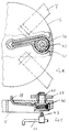
- 1 is the flank and 2 is the tread of the tire of a vehicle wheel 3, on which an anti-skid device with a running net 4 is mounted.
- the anti-skid device has a holder 5, on which by means of joints 6 forming pivot pins four support arms 7 are pivotally mounted such that they can be folded like the struts of an umbrella to reduce the storage space required for their storage.
- connection part 11 rotatable about the axis 9 of a fastening element 10.
- the connection part 11 is designed as a one-armed lever, the free end of which is aligned with an axis 12 of the vehicle wheel 3
- Position transferable bearing for a rotatable anchoring element 13 for a connecting strand 14 forms.
- the connecting strand 14 passes through a central opening 15 of the holder and can be pivoted into a guide channel 16, at the end of which cam-shaped latching members 17, 18 are arranged for locking the connecting strand 14.
- this is provided with pockets 19 for receiving compression springs 20 made of an elastomer.
- the shape of the compression springs 20 is selected so that a progressive spring characteristic is obtained.
- the compression springs 20 lie in the immediate vicinity of the joints 6 against the holding arms 7 made from straight strip steel sections and press the running net 4 onto the running surface 2.
- the straight shape of the holding arms which is favorable in terms of production technology, not only allows the distance to keep small between the bracket 5 and the wheel hub, but it also reduces the space required when stowing the unused anti-skid device.
- connection of the running net 4, which is preferably variable in length, to the holding arms 7 takes place via projections 21 of running power supplies 22.
- the projections 21 are provided with windows 23 which have pivot pins 24.
- the pivot pins 24 are encompassed by elongated eyelets 25 which are formed by rolled ends of the holding arms 7 reaching into the windows 23. Due to the slot-like design of the eyelets 25, flexing movements of the vehicle tire are taken into account.
- FIGS. 3 to 5 Two exemplary embodiments of compression springs 26 and 27 with a progressive characteristic are shown in FIGS. 3 to 5.
- the compression spring 26 consists of an elastomer, the compression spring 27 of spring steel. In both cases, the progressivity of the characteristic curve can be easily achieved by the respective shape of the compression springs.
- a pawl 28 can also be used to lock the connecting strand 14, as is shown in FIGS. 6 and 7.
- the pawl 28 is pivotally mounted about an axis 29 against the force of a return spring 30 in a bracket 31.
- One end of the pawl 28 forms a fork 32 for locking a member 33 of the connecting strand 34, while the other end forms a push button 35.
- One end of a flat, flexible band section 36 is suspended in the last link of the connecting strand 34.
- the band section 36 only has locking notches 37 which are used for its storage.
- the anti-skid device is pressed against the vehicle wheel 3 during assembly by the user exerting a corresponding pressure on the holder 5 with one hand.
- the holder 5 remains in the desired position, and the connecting strand can be pulled into the locking position.
- the band section 36 which is fixedly connected to the last link of the chain forming the connecting strand 34 and which has to be kept in the holder 5
- FIGS. 8 and 9 show a connecting strand 38 formed by a rope.
- the roller can be provided with a square hole 42 for the square pin 43 a crank 44 can be provided in order to facilitate the winding of the connecting strand 38 and, if necessary, even use it as a tensioning element.
Landscapes
- Engineering & Computer Science (AREA)
- Mechanical Engineering (AREA)
- Body Structure For Vehicles (AREA)
- Vehicle Cleaning, Maintenance, Repair, Refitting, And Outriggers (AREA)
- Formation And Processing Of Food Products (AREA)
- Confectionery (AREA)
- Braking Arrangements (AREA)
- Regulating Braking Force (AREA)
- Vehicle Body Suspensions (AREA)
Claims (20)
- Dispositif antidérapant pour roues de véhicule (3) comportant une attache (5) fixée sur la roue et orientable par rapport à celle-ci pour plusieurs bras de retenue (7) en forme de croisillon et supportant une armature de roulement réticulée et fermée (4), composée de nombreux éléments mobiles et solidaires entre eux, dans lequel, à l'état monté du dispositif antidérapant les bras de retenue (7 reliés à l'attache (5) par les articulations (6) sont appliqués avec leurs extrémités supportant l'armature de roulement réticulée (4), par élasticité, contre les flancs de la roue du véhicule (3) caractérisé en ce que les bras de retenue (7) prennent appui contre l'attache (5) via au moins un ressort de compression (20,26) (27) à distance des articulations (6) prévues pour eux.
- Dispositif antidérapant selon la revendication 1, caractérisé en ce que le ressort de compression (20, 26, 27) est placé à proximité des articulations (6) pour les bras de retenue (7)
- Dispositif antidérapant selon l'une des revendications 1 ou 2; caractérisé en ce que le ressort de compression (20,26,27a) présente une courbe caractéristique d'élasticité progressive.
- Dispositif antidérapant selon l'une des revendications 1 à 3; caractérisé en ce que chacun des bras de retenue (7)comporte un ressort de compression (20, 26, 27).
- Dispositif antidérapant selon l'une des revendications 1 à 4; caractérisé en ce que la course de chaque ressort de compression (20, 26, 27) est suffisamment longue pour transférer un tronçon de l'armature de roulement réticulée solidaire de l'un des bras de retenue (7), d'une position située à côté de la roue du véhicule (3), sur la surface de roulement decelle-ci.
- Dispositif antidérapant selon l'une des revendications 1 à (5); caractérisé en ce que le ou les ressorts de compression (20, 26, 27) est/sont conçu(s) en tant que butée(s)élastique(s) limitant le mouvement d'oscillation des bras de retenue (7) et de leurs articulations (6), à partir de la roue du véhicule (3).
- Dispositif antidérapant selon l'une des revendications 1 à 6; caractérisé en ce que le ou les ressorts de compression (20, 26, 27) vient/viennent en butée contre une longueur des bras de retenue (7) comprise entre les articulations (6) et les extrémités des bras de retenue (7) supportant l'armature de roulement réticulée (4).
- Dispositif antidérapant selon l'une des revendications 1 à 7; caractérisé en ce que les bras de retenue (7) sont élastiques.
- Dispositif antidérapant selon l'une des revendications 1 à 8; caractérisé en ce que les bras de retenue (7) sont formés de bandes rectilignes en acier.
- Dispositif antidérapant selon l'une des revendications 1 à 9; caractérisé en ce que les extrémités des bras de retenue (7), orientées vers l'armature de roulement réticulée, sont enroulées en forme d'oeillets oblongs 25 pour recevoir les tenons pivotants (24).
- Dispositif antidérapant selon l'une des revendications 1 à 10; caractérisé en ce que le ou les ressorts de compression (20, 26) est/sont fabriqués en un élastomère résistant aux basses températures.
- Dispositif antidérapant selon l'une des revendications 1 à 11, caractérisé en ce que le centre de l'attache (5) comporte une ouverture (15) pour un cordon d'assemblage (14, 34, 38) qui relie l'attache (5)à une pièce de raccordement (11) fixée sur la roue du véhicule (3).
- Dispositif antidéparapant selon la revendication 12, caractérisé en ce que le cordon d'assemblage (14,34,38) est relié à la pièce d'assemblage (11) au moyen d'un élément d'ancrage pivotant (13).
- Dispositif antidéparapant selon la revendication 12 ou 13, caractérisé en ce qu'une partie au moins du cordon d'assemblage (14,34) est formée en tant que chaîne.
- Dispositif antidérapant selon les revendications 12 à 14, caractérisé en ce que le cordon d'assemblage est constitué de deux sections (34,36).
- Dispositif antidérapant selon la revendication 15, caractérisé en ce que les sections du cordon d'assemblage sont reliées les unes aux autres de manière détachable.
- Dispositif antidérapant selon la revendication 12 ou 13 caractérisé en ce que le cordon d'assemblage (38) est formé d'un câble.
- Dispositif antidérapant selon l'une des revendications 12 à 17, caractérisé en ce que le cordon d'assemblage (14,34,38) peut être arrêté en position de raccordement par au moins un organe de sécurité de position.
- Dispositif antidérapant selon la revendication 18 caractérisé en ce que l'organe de sécurité de position est formé d'un cliquet d'arrêt (28).
- Dispositif antidérapant selon la revendication 18 ou 19, caractérisé en ce que l'organe de sécurité de position est formé d'un écrou de serrage (39).
Applications Claiming Priority (2)
| Application Number | Priority Date | Filing Date | Title |
|---|---|---|---|
| DE4018415 | 1990-06-06 | ||
| DE4018415A DE4018415C1 (en) | 1990-06-06 | 1990-06-06 | Antiskid cover on vehicle wheel - incorporates retaining member with arms engaging links on chain |
Publications (3)
| Publication Number | Publication Date |
|---|---|
| EP0460782A2 EP0460782A2 (fr) | 1991-12-11 |
| EP0460782A3 EP0460782A3 (en) | 1992-01-08 |
| EP0460782B1 true EP0460782B1 (fr) | 1994-08-31 |
Family
ID=6408061
Family Applications (1)
| Application Number | Title | Priority Date | Filing Date |
|---|---|---|---|
| EP91250145A Expired - Lifetime EP0460782B1 (fr) | 1990-06-06 | 1991-06-05 | Dispositif antidérapant |
Country Status (3)
| Country | Link |
|---|---|
| EP (1) | EP0460782B1 (fr) |
| AT (1) | ATE110648T1 (fr) |
| DE (2) | DE4018415C1 (fr) |
Cited By (2)
| Publication number | Priority date | Publication date | Assignee | Title |
|---|---|---|---|---|
| DE102009004807A1 (de) | 2009-01-13 | 2010-07-15 | Rud Ketten Rieger & Dietz Gmbh &. Co. Kg | Gleitschutzvorrichtung für Fahrzeugräder mit ergonomischer Handhabe |
| DE102010018251A1 (de) | 2010-04-23 | 2011-10-27 | Rud Ketten Rieger & Dietz Gmbh U. Co. Kg | Gleitschutzvorrichtung für Fahrzeugräder mit Spannungsanzeige |
Families Citing this family (7)
| Publication number | Priority date | Publication date | Assignee | Title |
|---|---|---|---|---|
| DE10137512C1 (de) * | 2001-07-26 | 2003-03-27 | Rud Ketten Rieger & Dietz | Gleitschutzvorrichtung für Fahrzeugräder |
| DE60334314D1 (de) | 2002-10-29 | 2010-11-04 | Maggi Catene Spa | Schnell montierbares gleitschutzsystem für fahrzeugräder und zugehörige vorrichtung zur befestigung am rad |
| CN100430248C (zh) * | 2003-07-30 | 2008-11-05 | 廉祥霖 | 机动车防滑履带 |
| JP2008513262A (ja) * | 2004-09-21 | 2008-05-01 | コンフオン・アクチエンゲゼルシヤフト | 車両用ホイールのための滑り止め装置 |
| ITMI20050574A1 (it) * | 2005-04-06 | 2006-10-07 | Maggi Catene Spa | Piastra di connessione perfezionata per una pista di rotolamento di una catena da neve |
| CH706195A1 (de) | 2012-03-06 | 2013-09-13 | Confon Ag | Vorrichtung zum Befestigen einer Gleitschutzkette. |
| FR3025744B1 (fr) * | 2014-09-15 | 2016-11-11 | Joubert Productions | Dispositif antiderapant pour roue de vehicule automobile |
Family Cites Families (4)
| Publication number | Priority date | Publication date | Assignee | Title |
|---|---|---|---|---|
| CH547182A (de) * | 1973-02-23 | 1974-03-29 | Mueller Fritz | Gleitschutzvorrichtung an fahrzeugraedern. |
| FR2350975A1 (fr) * | 1976-05-14 | 1977-12-09 | Simoncelli Giancarlo | Dispositif anti-derapant pour la neige, montable et demontable rapidement sans deplacement du vehicule |
| DE3545529A1 (de) * | 1985-12-20 | 1987-07-02 | Autotyp Sa | Schneekette fuer fahrzeugraeder |
| DE8816243U1 (de) * | 1988-12-30 | 1990-04-26 | Rud-Kettenfabrik Rieger & Dietz Gmbh U. Co, 7080 Aalen | Gleitschutzvorrichtung für Fahrzeugräder |
-
1990
- 1990-06-06 DE DE4018415A patent/DE4018415C1/de not_active Expired - Fee Related
-
1991
- 1991-06-05 EP EP91250145A patent/EP0460782B1/fr not_active Expired - Lifetime
- 1991-06-05 DE DE59102706T patent/DE59102706D1/de not_active Expired - Fee Related
- 1991-06-05 AT AT91250145T patent/ATE110648T1/de not_active IP Right Cessation
Cited By (2)
| Publication number | Priority date | Publication date | Assignee | Title |
|---|---|---|---|---|
| DE102009004807A1 (de) | 2009-01-13 | 2010-07-15 | Rud Ketten Rieger & Dietz Gmbh &. Co. Kg | Gleitschutzvorrichtung für Fahrzeugräder mit ergonomischer Handhabe |
| DE102010018251A1 (de) | 2010-04-23 | 2011-10-27 | Rud Ketten Rieger & Dietz Gmbh U. Co. Kg | Gleitschutzvorrichtung für Fahrzeugräder mit Spannungsanzeige |
Also Published As
| Publication number | Publication date |
|---|---|
| EP0460782A3 (en) | 1992-01-08 |
| DE4018415C1 (en) | 1991-10-17 |
| EP0460782A2 (fr) | 1991-12-11 |
| DE59102706D1 (de) | 1994-10-06 |
| ATE110648T1 (de) | 1994-09-15 |
Similar Documents
| Publication | Publication Date | Title |
|---|---|---|
| EP1409277B1 (fr) | Dispositif antipatinage destine a des roues de vehicules | |
| CH635036A5 (de) | Verstellbare rueckenlehne eines sitzes. | |
| DE3823661C2 (de) | Gleitschutzvorrichtung für Fahrzeugräder | |
| EP0460782B1 (fr) | Dispositif antidérapant | |
| EP2163408A1 (fr) | Chaîne de protection de glissement | |
| DE2133801C2 (de) | Reifenkette | |
| DE2556115A1 (de) | Schneekette fuer autoreifen | |
| EP0060804B1 (fr) | Chaîne antidérapante | |
| DE2757662C3 (de) | Ladefläche oder Brücke für Transportmittel | |
| EP0376428B1 (fr) | Système antidérapant pour roues de véhicule | |
| DE3545528A1 (de) | Rutschsicherungsvorrichtung fuer fahrzeugraeder | |
| DE3137311C2 (de) | Gleitschutzkette für Fahrzeugreifen | |
| EP0048686B1 (fr) | Chaîne antidérapante pour pneumatiques de véhicule | |
| EP0263778B1 (fr) | Chaîne pour pneumatique | |
| DE9107017U1 (de) | Gleitschutzvorrichtung | |
| DE19702815C1 (de) | Gleitschutzkette | |
| EP0125676B1 (fr) | Dispositif antidérapant pour pneumatiques de véhicules | |
| DE2160966A1 (de) | Gleitschutzkette mit einstellbarem Durchmesser | |
| DE3209992C2 (fr) | ||
| DE3111271A1 (de) | "gleitschutzkette" | |
| DE3137309A1 (de) | Gleitschutzkette | |
| AT410651B (de) | Schneekette | |
| EP1614555B1 (fr) | dispositif de serrage pour une chaîne antidérapante | |
| DE2638505A1 (de) | Skitraeger fuer kraftfahrzeuge | |
| EP1518719A1 (fr) | Chaíne antidérapante |
Legal Events
| Date | Code | Title | Description |
|---|---|---|---|
| PUAI | Public reference made under article 153(3) epc to a published international application that has entered the european phase |
Free format text: ORIGINAL CODE: 0009012 |
|
| PUAL | Search report despatched |
Free format text: ORIGINAL CODE: 0009013 |
|
| AK | Designated contracting states |
Kind code of ref document: A2 Designated state(s): AT CH DE FR IT LI |
|
| AK | Designated contracting states |
Kind code of ref document: A3 Designated state(s): AT CH DE FR IT LI |
|
| 17P | Request for examination filed |
Effective date: 19920513 |
|
| 17Q | First examination report despatched |
Effective date: 19931026 |
|
| GRAA | (expected) grant |
Free format text: ORIGINAL CODE: 0009210 |
|
| AK | Designated contracting states |
Kind code of ref document: B1 Designated state(s): AT CH DE FR IT LI |
|
| REF | Corresponds to: |
Ref document number: 110648 Country of ref document: AT Date of ref document: 19940915 Kind code of ref document: T |
|
| REF | Corresponds to: |
Ref document number: 59102706 Country of ref document: DE Date of ref document: 19941006 |
|
| ITF | It: translation for a ep patent filed | ||
| ET | Fr: translation filed | ||
| PLBI | Opposition filed |
Free format text: ORIGINAL CODE: 0009260 |
|
| 26 | Opposition filed |
Opponent name: CONFON AG Effective date: 19950531 |
|
| PLBO | Opposition rejected |
Free format text: ORIGINAL CODE: EPIDOS REJO |
|
| PLBN | Opposition rejected |
Free format text: ORIGINAL CODE: 0009273 |
|
| STAA | Information on the status of an ep patent application or granted ep patent |
Free format text: STATUS: OPPOSITION REJECTED |
|
| 27O | Opposition rejected |
Effective date: 19961018 |
|
| PGFP | Annual fee paid to national office [announced via postgrant information from national office to epo] |
Ref country code: FR Payment date: 19980617 Year of fee payment: 8 |
|
| PGFP | Annual fee paid to national office [announced via postgrant information from national office to epo] |
Ref country code: AT Payment date: 19980623 Year of fee payment: 8 |
|
| PGFP | Annual fee paid to national office [announced via postgrant information from national office to epo] |
Ref country code: CH Payment date: 19980701 Year of fee payment: 8 |
|
| PG25 | Lapsed in a contracting state [announced via postgrant information from national office to epo] |
Ref country code: AT Free format text: LAPSE BECAUSE OF NON-PAYMENT OF DUE FEES Effective date: 19990605 |
|
| PG25 | Lapsed in a contracting state [announced via postgrant information from national office to epo] |
Ref country code: FR Free format text: THE PATENT HAS BEEN ANNULLED BY A DECISION OF A NATIONAL AUTHORITY Effective date: 19990630 Ref country code: LI Free format text: LAPSE BECAUSE OF NON-PAYMENT OF DUE FEES Effective date: 19990630 Ref country code: CH Free format text: LAPSE BECAUSE OF NON-PAYMENT OF DUE FEES Effective date: 19990630 |
|
| REG | Reference to a national code |
Ref country code: CH Ref legal event code: PL |
|
| REG | Reference to a national code |
Ref country code: FR Ref legal event code: ST |
|
| PG25 | Lapsed in a contracting state [announced via postgrant information from national office to epo] |
Ref country code: IT Free format text: LAPSE BECAUSE OF NON-PAYMENT OF DUE FEES Effective date: 20050605 |
|
| PGFP | Annual fee paid to national office [announced via postgrant information from national office to epo] |
Ref country code: DE Payment date: 20080730 Year of fee payment: 18 |
|
| PGFP | Annual fee paid to national office [announced via postgrant information from national office to epo] |
Ref country code: IT Payment date: 20070629 Year of fee payment: 17 |
|
| PGRI | Patent reinstated in contracting state [announced from national office to epo] |
Ref country code: IT Effective date: 20091201 |
|
| PG25 | Lapsed in a contracting state [announced via postgrant information from national office to epo] |
Ref country code: DE Free format text: LAPSE BECAUSE OF NON-PAYMENT OF DUE FEES Effective date: 20100101 |
|
| PGRI | Patent reinstated in contracting state [announced from national office to epo] |
Ref country code: IT Effective date: 20091201 |