EP0460794B1 - Vanne de distribution - Google Patents
Vanne de distribution Download PDFInfo
- Publication number
- EP0460794B1 EP0460794B1 EP91302968A EP91302968A EP0460794B1 EP 0460794 B1 EP0460794 B1 EP 0460794B1 EP 91302968 A EP91302968 A EP 91302968A EP 91302968 A EP91302968 A EP 91302968A EP 0460794 B1 EP0460794 B1 EP 0460794B1
- Authority
- EP
- European Patent Office
- Prior art keywords
- seat
- gate
- seats
- guide means
- orifice
- Prior art date
- Legal status (The legal status is an assumption and is not a legal conclusion. Google has not performed a legal analysis and makes no representation as to the accuracy of the status listed.)
- Expired - Lifetime
Links
- 239000002184 metal Substances 0.000 claims abstract description 13
- 229910052751 metal Inorganic materials 0.000 claims abstract description 13
- 210000002105 tongue Anatomy 0.000 claims description 15
- 230000008602 contraction Effects 0.000 claims description 9
- 239000011810 insulating material Substances 0.000 claims description 4
- 229910000975 Carbon steel Inorganic materials 0.000 abstract description 9
- 239000010962 carbon steel Substances 0.000 abstract description 8
- 229910001220 stainless steel Inorganic materials 0.000 abstract description 8
- 239000010935 stainless steel Substances 0.000 abstract description 7
- 239000012530 fluid Substances 0.000 description 8
- 239000003779 heat-resistant material Substances 0.000 description 6
- 238000010276 construction Methods 0.000 description 3
- 238000005299 abrasion Methods 0.000 description 2
- 239000000463 material Substances 0.000 description 2
- 150000002739 metals Chemical class 0.000 description 2
- 239000002253 acid Substances 0.000 description 1
- 238000009413 insulation Methods 0.000 description 1
- 238000004519 manufacturing process Methods 0.000 description 1
- 238000012856 packing Methods 0.000 description 1
Images


Classifications
-
- F—MECHANICAL ENGINEERING; LIGHTING; HEATING; WEAPONS; BLASTING
- F16—ENGINEERING ELEMENTS AND UNITS; GENERAL MEASURES FOR PRODUCING AND MAINTAINING EFFECTIVE FUNCTIONING OF MACHINES OR INSTALLATIONS; THERMAL INSULATION IN GENERAL
- F16K—VALVES; TAPS; COCKS; ACTUATING-FLOATS; DEVICES FOR VENTING OR AERATING
- F16K27/00—Construction of housing; Use of materials therefor
- F16K27/04—Construction of housing; Use of materials therefor of sliding valves
- F16K27/044—Construction of housing; Use of materials therefor of sliding valves slide valves with flat obturating members
-
- F—MECHANICAL ENGINEERING; LIGHTING; HEATING; WEAPONS; BLASTING
- F16—ENGINEERING ELEMENTS AND UNITS; GENERAL MEASURES FOR PRODUCING AND MAINTAINING EFFECTIVE FUNCTIONING OF MACHINES OR INSTALLATIONS; THERMAL INSULATION IN GENERAL
- F16K—VALVES; TAPS; COCKS; ACTUATING-FLOATS; DEVICES FOR VENTING OR AERATING
- F16K11/00—Multiple-way valves, e.g. mixing valves; Pipe fittings incorporating such valves
- F16K11/02—Multiple-way valves, e.g. mixing valves; Pipe fittings incorporating such valves with all movable sealing faces moving as one unit
- F16K11/06—Multiple-way valves, e.g. mixing valves; Pipe fittings incorporating such valves with all movable sealing faces moving as one unit comprising only sliding valves, i.e. sliding closure elements
- F16K11/065—Multiple-way valves, e.g. mixing valves; Pipe fittings incorporating such valves with all movable sealing faces moving as one unit comprising only sliding valves, i.e. sliding closure elements with linearly sliding closure members
- F16K11/0655—Multiple-way valves, e.g. mixing valves; Pipe fittings incorporating such valves with all movable sealing faces moving as one unit comprising only sliding valves, i.e. sliding closure elements with linearly sliding closure members with flat slides
-
- Y—GENERAL TAGGING OF NEW TECHNOLOGICAL DEVELOPMENTS; GENERAL TAGGING OF CROSS-SECTIONAL TECHNOLOGIES SPANNING OVER SEVERAL SECTIONS OF THE IPC; TECHNICAL SUBJECTS COVERED BY FORMER USPC CROSS-REFERENCE ART COLLECTIONS [XRACs] AND DIGESTS
- Y10—TECHNICAL SUBJECTS COVERED BY FORMER USPC
- Y10T—TECHNICAL SUBJECTS COVERED BY FORMER US CLASSIFICATION
- Y10T137/00—Fluid handling
- Y10T137/6851—With casing, support, protector or static constructional installations
- Y10T137/7036—Jacketed
-
- Y—GENERAL TAGGING OF NEW TECHNOLOGICAL DEVELOPMENTS; GENERAL TAGGING OF CROSS-SECTIONAL TECHNOLOGIES SPANNING OVER SEVERAL SECTIONS OF THE IPC; TECHNICAL SUBJECTS COVERED BY FORMER USPC CROSS-REFERENCE ART COLLECTIONS [XRACs] AND DIGESTS
- Y10—TECHNICAL SUBJECTS COVERED BY FORMER USPC
- Y10T—TECHNICAL SUBJECTS COVERED BY FORMER US CLASSIFICATION
- Y10T137/00—Fluid handling
- Y10T137/8593—Systems
- Y10T137/877—With flow control means for branched passages
- Y10T137/87788—With valve or movable deflector at junction
- Y10T137/87804—Valve or deflector is tubular passageway
Definitions
- This invention relates generally to a diverter valve according to the preamble of claim 1, as known from US-A-3 771 561, and, more particularly, to improvements in a diverter valve of the type for use in controlling the flow of high temperature fluids through a valve body by means of a gate adapted to be guidably moved across the faces of side-by-side seats on the inner ends of outlets from the valve body in order to selectively open one while closing the other.
- valve body and its internal parts including seats, gate, and guides for maintaining the gate over one or the other of the seats are made of stainless steel which is resistant to such high temperatures.
- stainless steel is advantageous from this latter standpoint, it is quite expensive, and its use in the fabrication of the valve substantially increases the cost of the overall valve as compared, for example, to a valve of comparable size having its body and internal parts fabricated of a less expensive metal such as carbon steel.
- other metals such as carbon steel is more desirable, as, for example, in controlling polythionic acid to which stainless steel is susceptible to attack.
- the object of this invention is to provide a diverter valve of this type which is less expensive than the prior valve in that it is of such construction as to enable the body to be made of carbon steel or other less expensive metal despite the relative expansion and contraction of the body and internal parts with respect to one another.
- a valve of this type wherein the body is made of a metal such as carbon steel having relatively low resistance to heat, but having its inner surface lined with a heat insulating material, and the seats are so mounted on the body that they may expand and contract radially as well as axially with respect thereto as well as with respect to one another.
- the gate has guide means thereon which is guidably movable with respect to guide means on each of the seats whereby despite such relative expansion and contraction, the gate is maintained over one or the other of the faces of the seats to close it when the gate is moved between its alternative positions.
- the seats and other internal parts must be made of stainless steel or other relatively expensive heat resistant material to thereby substantially reduce the cost of the valve.
- the gate is guided with respect to each of the seats by tongues on each of its sides guidably movable within grooves on the seats, with the grooves being sufficiently wider than the tongues and flared at their oppositely facing ends so as to permit the tongues to move from one groove to the other despite relative expansion and contraction of the seats.
- the first and second outlets on the valve body comprise conduits on one side thereof, and each of the seats is mounted on a conduit by means of a frusto-conically shaped member connected at its large end to the inside of the conduit and its small end to the seat close to its orifice, thus maintaining the seats close to the side of the valve body in which the conduits are formed.
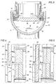
- the overall valve which is indicated in each of Figures 1, 2 and 3 by reference character 10, comprises a valve body 11 having a flat side 12 and a curved side 13 whose opposite ends are joined to the ends of the flat side 12, as best shown in Figure 3.
- the body also includes opposite ends 14 and 15 suitably bolted or welded to the ends of the sides, as shown. Normally, the valve is disposed on its side with the curved side 13 being uppermost.
- An inlet 16 to the valve body is formed within a conduit 17 connected to and extending outwardly from side wall 11, and a pair of outlets 18 and 19 from the body formed respectively within the conduits 20 and 21 connected to and extending outwardly from side-by-side openings in the sidewall 12 of the body.
- the walls of the valve body, including the conduits 17, 20 and 21, are made of a metal such as carbon steel having relatively low heat resistance.
- the inner surfaces of the valve body are covered by an insulating material 22 which protects the relatively low heat resistant metal from the extreme temperatures of the fluids to be controlled.
- valve is particularly well suited for use in a refinery or other environments in which high temperature fluids are to be controlled, and in which flow from the inlet is to be diverted through one or the other of the outlets.
- a first seat 23 is mounted on the valve body with its orifice 23A in alignment with the outlet 18 and a second seat 24 is mounted on the valve body with its orifice 24A in alignment with the outlet 19.
- the seats are disposed in side-by-side relation and with their inner seating faces in coplanar relation, whereby a gate 25 may be moved within the body between alternate positions closing one of the outlets and opening the other.
- the gate is disposed over the face of the seat 23 and across the orifice of the seat to close the outlet 18.
- the gate opens the orifice through the seat 23 and moves over the seat 24 and across the orifice therethrough to close the outlet 19.
- Each seat ring includes an orifice plate 30 having an orifice formed therein and a seat plate 31 having an orifice connected to one another by bolts 32 with the orifices aligned.
- each orifice in each orifice plate is covered by a ring 33 of abrasion resistant material, and the gate 25 is provided with a covering 40 of an abrasion resistant material on its inner side opposite the side engaging the face of the seats.
- each of the seats is mounted on the valve body by means of a frusto-conically shaped member 35 whose smaller end is connected to the seat plate 31 near its orifice and whose larger end is connected to the inner diameter of the conduit generally intermediate the inner and outer ends of the conduit. More particularly, the ends of the members 35 are welded to the conduits and seat plates so as to permit some flexibility between them and thus, as previously described, permit the seat rings to expand and contract axially as well as radially with respect to the valve body as well as with respect to one another.
- the frusto-conically shaped members 35 are especially well suited for this purpose, particularly since their connections to the conduits and the seats enables the seats to be disposed close to the adjacent wall of the valve body, thus maintaining the inside lateral dimensions of the valve body at a minimum.
- the gate is moved between its alternate positions by means of an operator 41 of any suitable construction and having a reciprocal stem 42 received through a packing 44 mounted on the end 14 of the valve body and connected to the upper end of the gate by a T-slot 43.
- This connection of the stem of the operator to the gate provides some degree of lateral movement of the gate with respect to the seats which is useful in maintaining the face of the gate against the face of the seat to be closed, as will be best understood from the description to follow.
- each groove 48 is substantially wider than the tongue 49 adapted to move within it and is flared at 50 at its end adjacent the opposite end of the other groove.
- the ends of the tongues are also tapered inwardly at 51.
- valve 10 requires that only the internal parts, including the seats, gate, mounting means, and guide means be made of stainless steel or other relatively expensive, high heat resistant material.
- the carbon steel or other relatively inexpensive metal of which the valve body is formed must be lined with a heat insulating material, this added cost is relatively small compared to the cost which would be encountered if the entire valve were made of the high heat resistant material.
- the heat resistant material may of course be fabricated and installed on the inner surfaces of the valve body in any suitable manner. As shown, it includes shapes which conform to the inner and outer sides of the frusto-conically shaped mounting members 35. In any case, the heat resistant material lines the inner surfaces of the valve so as to protect it against the heat, leaving only the seats and other internal parts which must be of a high heat resistant material.
Landscapes
- Engineering & Computer Science (AREA)
- General Engineering & Computer Science (AREA)
- Mechanical Engineering (AREA)
- Multiple-Way Valves (AREA)
- Sliding Valves (AREA)
- Lift Valve (AREA)
Claims (3)
- Vanne de dérivation (10) comprenant un carter extérieur (11) doté d'un orifice d'admission (16) et d'un premier et deuxième orifices d'écoulement (18, 19) disposés l'un à côté de l'autre, les premier et second sièges (23, 24) ayant à cet effet chacun un orifice (23A, 24A), des moyens (35) montés sur les premier et second sièges (23, 24) avec leur orifice (23A, 24A) alignés respectivement avec les premier et second orifices d'écoulement (18, 19), une vanne d'obturation (25) pouvant se déplacer avec le carter (11) d'une première position en travers du premier orifice (23A) pour fermer le premier orifice d'écoulement (18) et ouvrir le second (19) à une deuxième position en travers du second orifice (24A) pour fermer le second orifice d'écoulement (19) et ouvrir le premier (18), des moyens (45, 48-50) pour guider la vanne (25) entre ses positions d'ouverture et de fermeture, caractérisée en ce qu'un matériau isolant de la chaleur (22) tapisse la surface intérieure du carter (11), en ce que le moyen de montage du premier siège (35) est disposé sur le premier siège (23) permettant une dilatation et une rétraction tant transversales que longitudinales en fonction du premier orifice d'écoulement et en ce que le moyen de montage du second siège est disposé sur ce dernier permettant une dilatation et une rétraction en rapport avec le second orifice d'écoulement autant qu'en rapport avec le premier, en ce que le moyen de guidage comprend un moyen (45) sur le premier siège (23), un moyen (45) sur le second siège (24) et, un moyen (49) de la vanne (25) laquelle est guidée dans son déplacement vis-à-vis des premier et second moyens de guidage (45) de telle manière que la paroi de la vanne (25) soit maintenue très proche des faces des sièges (23, 24) lorsqu'elle se déplace entre ses première et seconde positions, et en ce que le carter (11) est fait d'un métal présentant une moindre résistance à la chaleur et un coefficient thermique de dilatation et de rétraction différent de celui du métal dont les sièges (23, 24) les moyens de montage (35) la vanne (25) et les moyens de guidage (45, 48-50) sont faits.
- Vanne de dérivation selon la revendication (1) dans laquelle le moyen de guidage (45) sur chaque siège (23, 24) possède de chaque côté des rainures longitudinales (48) et dans laquelle le moyen de guidage (49) de la vanne (25) comprend de chaque côté des languettes longitudinales (50) susceptibles de se déplacer en glissant dans les rainures (48) substantiellement plus larges que les languettes (50) leur permettant ainsi de passer d'une rainure à l'autre malgré la rétraction et la dilatation relatives des sièges (23, 24).
- Vanne de dérivation selon les revendications 1 ou 2, dans laquelle les premier et second orifices d'écoulement du carter (11) comprennent un premier et un deuxième conduits (18, 19) situés tous deux sur un côté du carter, le premier moyen de montage de siège comprenant une pièce de forme tronconique (35) reliée par sa petite base au première siège (23) situé près de son orifice (23A) et par sa grande base à l'intérieur du premier conduit (18), le second moyen de montage de siège comprenant une seconde pièce de forme tronconique (35) reliée par sa petite base au second siège (24) près de son orifice (24A) et par sa grande base à l'intérieur du second conduit (19).
Applications Claiming Priority (2)
| Application Number | Priority Date | Filing Date | Title |
|---|---|---|---|
| US07/535,187 US5029608A (en) | 1990-06-08 | 1990-06-08 | Diverter valve |
| US535187 | 2000-03-27 |
Publications (2)
| Publication Number | Publication Date |
|---|---|
| EP0460794A1 EP0460794A1 (fr) | 1991-12-11 |
| EP0460794B1 true EP0460794B1 (fr) | 1995-08-16 |
Family
ID=24133208
Family Applications (1)
| Application Number | Title | Priority Date | Filing Date |
|---|---|---|---|
| EP91302968A Expired - Lifetime EP0460794B1 (fr) | 1990-06-08 | 1991-04-04 | Vanne de distribution |
Country Status (5)
| Country | Link |
|---|---|
| US (1) | US5029608A (fr) |
| EP (1) | EP0460794B1 (fr) |
| JP (1) | JP2856948B2 (fr) |
| AT (1) | ATE126573T1 (fr) |
| DE (1) | DE69112133T2 (fr) |
Families Citing this family (8)
| Publication number | Priority date | Publication date | Assignee | Title |
|---|---|---|---|---|
| DE602006004993D1 (de) * | 2005-06-06 | 2009-03-12 | Ide Technologies Ltd | Kolben für ein linearschieberventil |
| US20100147527A1 (en) * | 2008-12-12 | 2010-06-17 | Paulo Cezar Silva Paulo | Subsea boosting cap system |
| CN102200190B (zh) * | 2010-03-25 | 2014-12-17 | 浙江三花制冷集团有限公司 | 一种四通换向阀 |
| US20150247577A1 (en) * | 2014-03-03 | 2015-09-03 | Idea Logic LLC | Diverter valve cartridge plate |
| CN105020435A (zh) * | 2015-08-03 | 2015-11-04 | 宁波长荣酿造设备有限公司 | 风送换向阀 |
| CN105351567A (zh) * | 2015-12-15 | 2016-02-24 | 岳阳东方自控工程设备有限公司 | 插板式三通分流阀 |
| NL2019183B1 (en) * | 2017-07-05 | 2019-01-16 | Leo Dynamische Investering B V | Dredge gate valve |
| CN108533790A (zh) * | 2018-06-28 | 2018-09-14 | 安徽省白嘉信息技术有限公司 | 一种热水器用水路转换阀 |
Family Cites Families (12)
| Publication number | Priority date | Publication date | Assignee | Title |
|---|---|---|---|---|
| DE1086085B (de) * | 1957-07-11 | 1960-07-28 | Spanner Boilers Ltd | Zweiwegschieber fuer die Auspuffleitung von Brennkraftmaschinen |
| US3132669A (en) * | 1961-03-13 | 1964-05-12 | Grann Flow Equipment Ltd | Pipe conveyor diversion valve |
| US3624882A (en) * | 1968-06-19 | 1971-12-07 | Dezurik Corp | Method of making and assembling lined gate valves |
| US3592221A (en) * | 1969-12-01 | 1971-07-13 | Exxon Research Engineering Co | Plate swing valve |
| US3701359A (en) * | 1971-01-25 | 1972-10-31 | Exxon Research Engineering Co | High temperature slide valve |
| US3726306A (en) * | 1971-05-20 | 1973-04-10 | Texas Alloy Prod Co | Refinery control valve |
| US3771561A (en) * | 1972-03-14 | 1973-11-13 | J Santamaria | Valve |
| DE2242087C2 (de) * | 1972-08-26 | 1983-10-13 | Exxon Research and Engineering Co., 07036 Linden, N.J. | Absperrschieber |
| US3976094A (en) * | 1975-01-13 | 1976-08-24 | Tapco International, Inc. | Guided slide valve |
| US3964507A (en) * | 1975-01-13 | 1976-06-22 | Tapco International, Inc. | Slide valve with integrated removable internals |
| GB1595815A (en) * | 1978-03-21 | 1981-08-19 | Vesuvius Int Corp | Flow control device for molten metal |
| GB2185302A (en) * | 1986-01-15 | 1987-07-15 | Exxon Research Engineering Co | Valve for use with hot gas containing entrained particles |
-
1990
- 1990-06-08 US US07/535,187 patent/US5029608A/en not_active Expired - Lifetime
-
1991
- 1991-04-04 DE DE69112133T patent/DE69112133T2/de not_active Expired - Fee Related
- 1991-04-04 AT AT91302968T patent/ATE126573T1/de not_active IP Right Cessation
- 1991-04-04 EP EP91302968A patent/EP0460794B1/fr not_active Expired - Lifetime
- 1991-06-03 JP JP3157351A patent/JP2856948B2/ja not_active Expired - Fee Related
Also Published As
| Publication number | Publication date |
|---|---|
| JPH04231779A (ja) | 1992-08-20 |
| EP0460794A1 (fr) | 1991-12-11 |
| DE69112133D1 (de) | 1995-09-21 |
| US5029608A (en) | 1991-07-09 |
| JP2856948B2 (ja) | 1999-02-10 |
| ATE126573T1 (de) | 1995-09-15 |
| DE69112133T2 (de) | 1996-04-25 |
Similar Documents
| Publication | Publication Date | Title |
|---|---|---|
| EP0460794B1 (fr) | Vanne de distribution | |
| US3701359A (en) | High temperature slide valve | |
| US4182122A (en) | Insulated exhaust manifold | |
| AU592504B2 (en) | Face seal for a valve seat | |
| US3976094A (en) | Guided slide valve | |
| EP0247275B1 (fr) | Robinet-vanne résistant au feu | |
| US4535801A (en) | Multi-purge gate valve for particulate solids flow | |
| US3937247A (en) | Valve for fluids containing abrasive particles | |
| US5895028A (en) | Single disc slide valve with center biased flow | |
| US2438312A (en) | Expansion joint for high temperatures | |
| EP0864062B1 (fr) | Joint articule flexible | |
| US4082105A (en) | Valve stem packing assembly with temperature responsive seal | |
| US2792845A (en) | Acidproof control valve | |
| RU94040912A (ru) | Защитное устройство против выхода из строя при избыточном давлении напорного резервуара ядерного реактора | |
| US5106106A (en) | Sealing structure for use in guiding molten metal from a metallurgical vessel and a seal thereof | |
| US3669149A (en) | Direct sluice valve for pipes conveying products at high temperature | |
| ITRE940001A1 (it) | Valvola girevole. | |
| US4261385A (en) | Cylinder valve | |
| US3396992A (en) | Connector for hot fluid conduits | |
| US4337789A (en) | Shut-off valve for interrupting a flow of a fluid through a pipeline | |
| US2779609A (en) | Flexible seal for pipes passing through a wall | |
| EP0049916A1 (fr) | Vanne comprenant un mécanisme pour appliquer les sièges contre l'élément obturateur | |
| US5188145A (en) | Valve | |
| US5062445A (en) | Water cooled gate valve | |
| US4296776A (en) | Gate valve for use in large size conduits |
Legal Events
| Date | Code | Title | Description |
|---|---|---|---|
| PUAI | Public reference made under article 153(3) epc to a published international application that has entered the european phase |
Free format text: ORIGINAL CODE: 0009012 |
|
| AK | Designated contracting states |
Kind code of ref document: A1 Designated state(s): AT BE CH DE DK ES FR GB GR IT LI LU NL SE |
|
| 17P | Request for examination filed |
Effective date: 19920605 |
|
| 17Q | First examination report despatched |
Effective date: 19940331 |
|
| GRAA | (expected) grant |
Free format text: ORIGINAL CODE: 0009210 |
|
| AK | Designated contracting states |
Kind code of ref document: B1 Designated state(s): AT BE CH DE DK ES FR GB GR IT LI LU NL SE |
|
| PG25 | Lapsed in a contracting state [announced via postgrant information from national office to epo] |
Ref country code: DK Effective date: 19950816 Ref country code: FR Free format text: THE PATENT HAS BEEN ANNULLED BY A DECISION OF A NATIONAL AUTHORITY Effective date: 19950816 Ref country code: NL Free format text: LAPSE BECAUSE OF FAILURE TO SUBMIT A TRANSLATION OF THE DESCRIPTION OR TO PAY THE FEE WITHIN THE PRESCRIBED TIME-LIMIT Effective date: 19950816 Ref country code: GR Free format text: LAPSE BECAUSE OF FAILURE TO SUBMIT A TRANSLATION OF THE DESCRIPTION OR TO PAY THE FEE WITHIN THE PRESCRIBED TIME-LIMIT Effective date: 19950816 Ref country code: CH Effective date: 19950816 Ref country code: LI Effective date: 19950816 Ref country code: BE Effective date: 19950816 Ref country code: ES Free format text: THE PATENT HAS BEEN ANNULLED BY A DECISION OF A NATIONAL AUTHORITY Effective date: 19950816 Ref country code: AT Effective date: 19950816 |
|
| REF | Corresponds to: |
Ref document number: 126573 Country of ref document: AT Date of ref document: 19950915 Kind code of ref document: T |
|
| ITF | It: translation for a ep patent filed | ||
| REF | Corresponds to: |
Ref document number: 69112133 Country of ref document: DE Date of ref document: 19950921 |
|
| PG25 | Lapsed in a contracting state [announced via postgrant information from national office to epo] |
Ref country code: SE Effective date: 19951116 |
|
| EN | Fr: translation not filed | ||
| NLV1 | Nl: lapsed or annulled due to failure to fulfill the requirements of art. 29p and 29m of the patents act | ||
| PG25 | Lapsed in a contracting state [announced via postgrant information from national office to epo] |
Ref country code: LU Free format text: LAPSE BECAUSE OF NON-PAYMENT OF DUE FEES Effective date: 19960430 |
|
| PLBE | No opposition filed within time limit |
Free format text: ORIGINAL CODE: 0009261 |
|
| STAA | Information on the status of an ep patent application or granted ep patent |
Free format text: STATUS: NO OPPOSITION FILED WITHIN TIME LIMIT |
|
| 26N | No opposition filed | ||
| REG | Reference to a national code |
Ref country code: GB Ref legal event code: IF02 |
|
| PGFP | Annual fee paid to national office [announced via postgrant information from national office to epo] |
Ref country code: GB Payment date: 20020327 Year of fee payment: 12 |
|
| PGFP | Annual fee paid to national office [announced via postgrant information from national office to epo] |
Ref country code: DE Payment date: 20020418 Year of fee payment: 12 |
|
| PG25 | Lapsed in a contracting state [announced via postgrant information from national office to epo] |
Ref country code: GB Free format text: LAPSE BECAUSE OF NON-PAYMENT OF DUE FEES Effective date: 20030404 |
|
| PG25 | Lapsed in a contracting state [announced via postgrant information from national office to epo] |
Ref country code: DE Free format text: LAPSE BECAUSE OF NON-PAYMENT OF DUE FEES Effective date: 20031101 |
|
| GBPC | Gb: european patent ceased through non-payment of renewal fee |
Effective date: 20030404 |
|
| PGFP | Annual fee paid to national office [announced via postgrant information from national office to epo] |
Ref country code: IT Payment date: 20070604 Year of fee payment: 17 |
|
| PG25 | Lapsed in a contracting state [announced via postgrant information from national office to epo] |
Ref country code: IT Free format text: LAPSE BECAUSE OF NON-PAYMENT OF DUE FEES Effective date: 20080404 |