EP0460916A2 - Format et méthode d'enregistrement digitale d'information économisant des rotations supplémentaires, sur des disques nécessitant un pré-effacement - Google Patents
Format et méthode d'enregistrement digitale d'information économisant des rotations supplémentaires, sur des disques nécessitant un pré-effacement Download PDFInfo
- Publication number
- EP0460916A2 EP0460916A2 EP91305042A EP91305042A EP0460916A2 EP 0460916 A2 EP0460916 A2 EP 0460916A2 EP 91305042 A EP91305042 A EP 91305042A EP 91305042 A EP91305042 A EP 91305042A EP 0460916 A2 EP0460916 A2 EP 0460916A2
- Authority
- EP
- European Patent Office
- Prior art keywords
- data
- track
- record
- erased
- erase
- Prior art date
- Legal status (The legal status is an assumption and is not a legal conclusion. Google has not performed a legal analysis and makes no representation as to the accuracy of the status listed.)
- Withdrawn
Links
Images
Classifications
-
- G—PHYSICS
- G11—INFORMATION STORAGE
- G11B—INFORMATION STORAGE BASED ON RELATIVE MOVEMENT BETWEEN RECORD CARRIER AND TRANSDUCER
- G11B20/00—Signal processing not specific to the method of recording or reproducing; Circuits therefor
- G11B20/10—Digital recording or reproducing
- G11B20/12—Formatting, e.g. arrangement of data block or words on the record carriers
- G11B20/1217—Formatting, e.g. arrangement of data block or words on the record carriers on discs
- G11B20/1252—Formatting, e.g. arrangement of data block or words on the record carriers on discs for discontinuous data, e.g. digital information signals or computer program data
-
- G—PHYSICS
- G11—INFORMATION STORAGE
- G11B—INFORMATION STORAGE BASED ON RELATIVE MOVEMENT BETWEEN RECORD CARRIER AND TRANSDUCER
- G11B11/00—Recording on or reproducing from the same record carrier wherein for these two operations the methods are covered by different main groups of groups G11B3/00 - G11B7/00 or by different subgroups of group G11B9/00; Record carriers therefor
- G11B11/10—Recording on or reproducing from the same record carrier wherein for these two operations the methods are covered by different main groups of groups G11B3/00 - G11B7/00 or by different subgroups of group G11B9/00; Record carriers therefor using recording by magnetic means or other means for magnetisation or demagnetisation of a record carrier, e.g. light induced spin magnetisation; Demagnetisation by thermal or stress means in the presence or not of an orienting magnetic field
- G11B11/105—Recording on or reproducing from the same record carrier wherein for these two operations the methods are covered by different main groups of groups G11B3/00 - G11B7/00 or by different subgroups of group G11B9/00; Record carriers therefor using recording by magnetic means or other means for magnetisation or demagnetisation of a record carrier, e.g. light induced spin magnetisation; Demagnetisation by thermal or stress means in the presence or not of an orienting magnetic field using a beam of light or a magnetic field for recording by change of magnetisation and a beam of light for reproducing, i.e. magneto-optical, e.g. light-induced thermomagnetic recording, spin magnetisation recording, Kerr or Faraday effect reproducing
- G11B11/10502—Recording on or reproducing from the same record carrier wherein for these two operations the methods are covered by different main groups of groups G11B3/00 - G11B7/00 or by different subgroups of group G11B9/00; Record carriers therefor using recording by magnetic means or other means for magnetisation or demagnetisation of a record carrier, e.g. light induced spin magnetisation; Demagnetisation by thermal or stress means in the presence or not of an orienting magnetic field using a beam of light or a magnetic field for recording by change of magnetisation and a beam of light for reproducing, i.e. magneto-optical, e.g. light-induced thermomagnetic recording, spin magnetisation recording, Kerr or Faraday effect reproducing characterised by the transducing operation to be executed
- G11B11/10517—Overwriting or erasing
-
- G—PHYSICS
- G11—INFORMATION STORAGE
- G11B—INFORMATION STORAGE BASED ON RELATIVE MOVEMENT BETWEEN RECORD CARRIER AND TRANSDUCER
- G11B19/00—Driving, starting, stopping record carriers not specifically of filamentary or web form, or of supports therefor; Control thereof; Control of operating function ; Driving both disc and head
- G11B19/02—Control of operating function, e.g. switching from recording to reproducing
-
- G—PHYSICS
- G11—INFORMATION STORAGE
- G11B—INFORMATION STORAGE BASED ON RELATIVE MOVEMENT BETWEEN RECORD CARRIER AND TRANSDUCER
- G11B27/00—Editing; Indexing; Addressing; Timing or synchronising; Monitoring; Measuring tape travel
- G11B27/02—Editing, e.g. varying the order of information signals recorded on, or reproduced from, record carriers
- G11B27/031—Electronic editing of digitised analogue information signals, e.g. audio or video signals
- G11B27/036—Insert-editing
-
- G—PHYSICS
- G11—INFORMATION STORAGE
- G11B—INFORMATION STORAGE BASED ON RELATIVE MOVEMENT BETWEEN RECORD CARRIER AND TRANSDUCER
- G11B27/00—Editing; Indexing; Addressing; Timing or synchronising; Monitoring; Measuring tape travel
- G11B27/10—Indexing; Addressing; Timing or synchronising; Measuring tape travel
- G11B27/19—Indexing; Addressing; Timing or synchronising; Measuring tape travel by using information detectable on the record carrier
- G11B27/24—Indexing; Addressing; Timing or synchronising; Measuring tape travel by using information detectable on the record carrier by sensing features on the record carrier other than the transducing track ; sensing signals or marks recorded by another method than the main recording
-
- G—PHYSICS
- G11—INFORMATION STORAGE
- G11B—INFORMATION STORAGE BASED ON RELATIVE MOVEMENT BETWEEN RECORD CARRIER AND TRANSDUCER
- G11B27/00—Editing; Indexing; Addressing; Timing or synchronising; Monitoring; Measuring tape travel
- G11B27/10—Indexing; Addressing; Timing or synchronising; Measuring tape travel
- G11B27/19—Indexing; Addressing; Timing or synchronising; Measuring tape travel by using information detectable on the record carrier
- G11B27/28—Indexing; Addressing; Timing or synchronising; Measuring tape travel by using information detectable on the record carrier by using information signals recorded by the same method as the main recording
- G11B27/30—Indexing; Addressing; Timing or synchronising; Measuring tape travel by using information detectable on the record carrier by using information signals recorded by the same method as the main recording on the same track as the main recording
- G11B27/3027—Indexing; Addressing; Timing or synchronising; Measuring tape travel by using information detectable on the record carrier by using information signals recorded by the same method as the main recording on the same track as the main recording used signal is digitally coded
-
- G—PHYSICS
- G11—INFORMATION STORAGE
- G11B—INFORMATION STORAGE BASED ON RELATIVE MOVEMENT BETWEEN RECORD CARRIER AND TRANSDUCER
- G11B7/00—Recording or reproducing by optical means, e.g. recording using a thermal beam of optical radiation by modifying optical properties or the physical structure, reproducing using an optical beam at lower power by sensing optical properties; Record carriers therefor
- G11B7/007—Arrangement of the information on the record carrier, e.g. form of tracks, actual track shape, e.g. wobbled, or cross-section, e.g. v-shaped; Sequential information structures, e.g. sectoring or header formats within a track
- G11B7/00745—Sectoring or header formats within a track
-
- G—PHYSICS
- G11—INFORMATION STORAGE
- G11B—INFORMATION STORAGE BASED ON RELATIVE MOVEMENT BETWEEN RECORD CARRIER AND TRANSDUCER
- G11B20/00—Signal processing not specific to the method of recording or reproducing; Circuits therefor
- G11B20/10—Digital recording or reproducing
- G11B20/12—Formatting, e.g. arrangement of data block or words on the record carriers
- G11B20/1217—Formatting, e.g. arrangement of data block or words on the record carriers on discs
- G11B2020/1257—Count Key Data [CKD] format
-
- G—PHYSICS
- G11—INFORMATION STORAGE
- G11B—INFORMATION STORAGE BASED ON RELATIVE MOVEMENT BETWEEN RECORD CARRIER AND TRANSDUCER
- G11B2220/00—Record carriers by type
- G11B2220/20—Disc-shaped record carriers
- G11B2220/25—Disc-shaped record carriers characterised in that the disc is based on a specific recording technology
- G11B2220/2525—Magneto-optical [MO] discs
-
- G—PHYSICS
- G11—INFORMATION STORAGE
- G11B—INFORMATION STORAGE BASED ON RELATIVE MOVEMENT BETWEEN RECORD CARRIER AND TRANSDUCER
- G11B27/00—Editing; Indexing; Addressing; Timing or synchronising; Monitoring; Measuring tape travel
- G11B27/02—Editing, e.g. varying the order of information signals recorded on, or reproduced from, record carriers
- G11B27/031—Electronic editing of digitised analogue information signals, e.g. audio or video signals
- G11B27/034—Electronic editing of digitised analogue information signals, e.g. audio or video signals on discs
Definitions
- the present invention relates to recording digital signals on a magneto-optic recording medium, such as a rotatable disk.
- Optical disks in current use are often hard sectored by molding the sector identifications into the disk at time of its manufacture.
- the present invention is also usable to advantage for such hard-sectored disks.
- US patent 4,814,903 refers to such hard-sectored optical disks and shows one format for such disks. In all of the above-referred to formats, a gap is usually provided between successive data storing areas of the track. It is believed that the greatest advantage is for CKD formatted disks which are usually the disks used in the higher performance disk drives.
- data storage apparatus having means for storing data as a plurality of data areas on a storage medium, the medium requiring erasure of any data previously stored on a data area before further data is written to that area, characterised by means for storing, on the medium, a data item associated with one or more of the data areas, indicating whether any previously recorded data has already been erased from that area or areas.
- the present invention also provides a method of operating data storage apparatus having means for storing data as a plurality of data areas on a storage medium, the medium requiring erasure of any data previously stored on a data area before further data is written to that area, comprising the step of storing, on the medium, a data item associated with one or more of the data areas, indicating whether any previously recorded data has already been erased from that area or areas.
- track erasure indicators are inserted into each track for indicating the erasure status of predetermined portions of a track, preferably addressable portions of a track. Such predetermined portions are less than the extent of a given track or circumvolution of a disk.
- One erasure indicator is placed between two records for indicating the erasure status of the track remote from the two records.
- each track has an index mark, the two records are located adjacent the index mark or line and the erasure indicator indicates the erased status of the track portion not occupied by records recorded in such track taken in the direction of relative motion of the record member with respect to a transducer or laser beam used with the disk.
- the invention provides machine operation controls for record media having pre-erasure recording requirements which facilitate controlling usage of such media, and in particular applies to magneto-optic media.
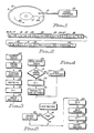
- Magneto-optic recording disk 10 has a recording area 11 consisting of a large plurality of data storing tracks (not separately shown).
- a single radial track index line 12 (which can be embossed, molded or magnetically recorded) extends across recording area 11. This index line identifies the beginning (BOT) and end (EOT) of each of the tracks.
- a transducer arm assembly 13 has the usual optics, including an objective or focussing lens at its distal end.
- Circle 13M represents polarity reversible means for providing a magnetic bias or steering field in disk 10 for writing and erasing, as is known.
- One magnetic polarity is for erasure and an opposite magnetic polarity is for writing.
- Other portions 14 represent the remainder portions of an optical disk drive, as is known, and schematically illustrated in Kulakowski, supra.
- sector identifying marks extend radially of the recording area 11 to denote a plurality of equal-sized data storing sectors on a data storing disk. While the present invention can be practised with either type of formatting, it is preferred that the CKD format be used because of increased areal efficiency.
- Control indicia are interposed between at least two records, blocks or sectors of data for indicating the erased state of the respective tracks beyond the adjacent record, block or sector to be next scanned by a transducer of head assembly 13.
- Fig. 2 illustrates a single CKD formatted track 15, in which the index mark 12 denotes the beginning of track 15.
- An initial gap 16 separates index mark or line 12 from the first record 17, the Home Address record HA described by Bohl, supra, in Fig. 4-1 on page 73.
- Gap 18 separates HA 17 from control indicia E 19, added to the Bohl et al described format, as will be later detailed.
- E indicia 30 and 33 represent the last two E indicia recording in track 15; the last E indicia 33 signifies the erased status of area 34, that portion of track 15 lying between the last record RN-1 and index line 12.
- An advantage of the present embodiment found when updating track 15, as by adding records in area 34. Sensing the last E indicia 33 before scanning record RN-1 enables other portions 14 to determine whether area 34 is erased. This action enables, if area 34 is erased, recording without an intervening pre-write erasing operation (saves one disk rotation in most data recording operations, as will become apparent), or if area 34 is not erased to perform a pre-write erasure. When area 34 is erased, the E indicia enable other portions 14 to avoid an additional rotation usually required for pre-write erasure. Keeping the erased condition indicators on the disk 10 provides a simple low-cost erase indications for a multiplicity of data-storing tracks.
- the E indicia 19, 26, 30 and 33 may consist of any signal pattern that is reliably sensible. Such a signal pattern can be an erased area in any of the E indicia locations for indicating either a binary 0 or binary 1, as determined by a designer.
- the indicia control indications follow the rules that if the track area beyond the next record to be scanned is erased (whether in a current track or another track), then the value of the indicia is true (area erased) indicated in the present invention by binary 1. When the area of the track beyond the next record to be scanned is not erased, then the E indicia indicates false, herein represented by a binary 0. In Fig.
- the E indicia 19, 26 and 30 are all "0" because records are recorded after the next scanned record, respectively.
- the E indicia 33 is binary 0 when the area 34 following record RN-1 in the current direction of relative motion of disk 10 is erased and is a binary 1 when such following area is not erased.
- E indicia 19 is provided in each track.
- E indicia 19 is a binary 0 whenever area 34 is not erased or its erasure status is unknown and is a binary 1 whenever area 34 is known to be erased.
- the E indicia 19 is an erased area for indicating a binary 1.
- each E indicia signifies the erased status only for the sector or fixed block data storing area just beyond the next record to be scanned.
- E indicia 19 signifies the erased status of record storing area denominated as record 28 just beyond next scanned record 23.
- Timing considerations in record area accessing may suggest other variations of the erasure indications used in accordance with the present invention.
- Another factor in selecting the E indicia location is the time required to reverse the magnetic bias field direction between an erasing polarity and a writing or recording polarity. The shorter the time to access and reverse magnetic polarity, the closer the E indicia can be placed to the pointed to sector, block or area.
- control using the E indicia be placed between adjacent records, no limitation thereto is intended.
- the E indicia can be included in the count field, in sector ID portions of FBA disks, and the like.
- Fig. 3 illustrates the machine operations effected for formatting a CKD track on a disk.
- a format track command is to be executed under control of other portions 14, is effected by microprogramming being executed by a microprocessor (not shown) of other portions 14.
- the traclk is erased using known techniques.
- a surface analysis step 42 is performed in a known manner for identifying defect locations in the track and for effecting known defect skipping in CKD formatted tracks.
- home address record HA is recorded (including recording gaps) followed by recording E indicia 19 in step 44 to indicate a binary 1.
- record R0 is written at step 45. Now the track is formatted for receiving user data in records number R1 and higher.
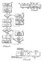
- Fig. 4 illustrates the machine operations for deallocating a track. Allocation of a CKD track is known and follows usual procedures. The Fig. 3 illustrated formatting can occur upon the first allocation of the respective track or can be performed before allocations during idle times of the Fig. 1 illustrated storage apparatus.
- a deallocate track command is entered at step 50, as by calling a microprogram routine (not shown) in other portions 1.4. Then, at step 51, other portions 14 determined whether or not to pre-write erase the just deallocated track. If not, then the just deallocated track is identified as a free but not erased track: see Kulakowski et al, supra for space management associated with such an operation.
- the track is accessed, the E indicia 19 is changed from indicating a binary 0 (records are on the track) to a binary 1 for indicating pre-write erasure. Then at step 54, the track is erased from the end of record R0 23, beginning with gap 25 to EOT at index line 12. Now area 34 extends from R0 to index line 12.
- the track is first erased as above described; upon completion of the erasure, E indicia 19 is set to indicate binary 0. Either procedure is acceptable; for maximal system integrity the alternate procedure should be used.
- Fig. 5 is a simplified chart of machine operations usable for adding one record to existing recording in one track.
- An add record command begins at step 60.
- other portions 14 determine whether or not a pre-write erase (PWE) is included with the write command. If yes, then at step 62 the accessed track to be written to is erased from the end of the last record N-1 in the track to the index line 12 (end of the track or EOT).
- PWE pre-write erase
- This partial-track erasure can be effected by a known command "Perform Subsystem Function" which commands a peripheral controller that a designeated track is to be erased from the last record upto the index line 12. Such an erasure from a last written record in a track to the index line 12 has also been termed a "data security erase".
- Machine operations from step 61 without a PWE required and from erase step 62 joint step 63 to reset the E indicia preceding the last current record to binary 0.
- This action indicates that the area just beyond the current last record N-1 is no longer erased, i.e. one record has been added.
- the last record N-1 is skipped at machine step 65, followed by writing a new E indicia for the newly added record with E being equal to binary 1 (the area after the new record is erased). Finally, the record is written to the track at machine step 66 and now becomes the last record on the track.
- the track access occurs before the last E indicia 33 is encountered by the transducer.
- the true-false indication of E indicia 33 is sensed, as later described.
- the E bit is set to binary 0.
- the next record N-1 is skipped.
- the one record, to be the last record on the track is written at step 79.
- the write procedure is now complete.
- step 75 If at step 75, it is determined that more than one record is to be appended to the current last record, then a machine operations loop ofsteps 76 and 77 is repeatedly performed until a last record is yet to be recorded.
- the E bit is set to binary 0 indicating more than one record exists beyond the E bit and a next record is recorded.
- step 77 other portions 14 determine whether or not the next record to be recorded is the last record. If not the loop 76-77 is repeated. If the next record is to be the last record, then steps 78 and 79, above-described are performed to complete the recording operation.
- step 80 the record N-1 is skipped. While the record is being skipped, other portions 12 switch the magnetic bias field represented by circle 13M of Fig. 1 to the erase polarity.
- step 81 the track is erased beginning at the end of the record N-1 to EOT at index line 12. Now writing the records to be appended can ensue.
- step 82 rotational position of record N-1 is acquired and skipped. Then, steps 73 et seq are performed as described above.
- Fig. 7 illustrates circumferential spacing of track indexes (BOT and EOT indicators) from track to track to enable switching from one track to an adjacent track when format writing a plurality of adjacent tracks successively.
- This description assumes that read while erase/write as described for Fig. 8 is not being used. This procedure is particularly useful when only E indicia 19 are used.
- the index (BOT and EOT), of each track is circumferentially offset from the indexes of radially adjacent tracks to enable switching the laser beam from one track to an adjacent track for reading the E indicium of the adjacent track, then switching back to the first track.
- the E indicium on one track signifies the pre-write erasure of an adjacent track which has an index scanned by the transducer assembly 13 before the assembly 13 scans the index in the one track.
- Disk 10 is moving in the direction of arrow 89 with respect to transducer assembly 13 (Fig. 1).
- the E indicia 93 immediately following HA 92 and index 91 of track 90 describes the pre-write erasure status of an adjacent track (not shown) having its index circumferentially displaced on the disk 10 a predetermined distance in the direction of arrow 89.
- Another application for the circumferential displacement of indexes for adjacent tracks is to enable continuous scanning of the HA, E indicia, and R0 of a series of tracks. Such a continuous scan enables ascertaining pre-write erasure status of a plurality of tracks with a minimal number of disk rotations.
- the symbol "E + E" in E indicia 93 and 100 indicates that a plurality of E indicia may be included between circumferentially adjacent records in a tracks, such as between HA and R0 of such tracks.
- One of the E indicia can indicate the pre-write erasure for an adjacent track while a second one of the E indicia can indicate the pre-write erasure status of the current track.
- Such plural indications can be used with a single index line 12 as well as with circumferentially displaced indexes.
- the value of the last E indicia 33 can be read to verify it being a binary 0 or 1 by reading such E indicia while erasing it.
- Fig. 8 illustrates how this read while erase operation is effected.
- An erasing laser beam 111 emitted by head assembly 13 in a known manner impinges on magneto-optic track 15 which is moving under the beam 111 in the direction of arrow 112. Erasure is effected by heating the area of track 15 under beam 111 to be above the Curie temperature while a biasing magnetic field causes the magnetic remanence occurring as the area cools to assume the polarity of the bias field.
- Such heating has a finite delay; that is area 116 which is the leading edge portion of erasing beam 111 is below the Curie temperature; thus any light reflected from track 15 still indicates the previous magnetic remanence in accordance with the Kerr effect. Detecting the rotation of light polarization indicates the previous state of the remanent magnetization in area 116. Erasure occurs in the shaded area 113 with the temperature of the area under erasure beam 111 increasing toward the Curie tempera ⁇ ture as indicated by dashed lines 114 and 115. The track temperature cools after the track has passed under the erasing beam 111.
- the above-described procedure also enables writing a long area of non-erasure tone(s), one tone frequency signifying a binary 0 and a second tone frequency signifying a binary 1.
Landscapes
- Engineering & Computer Science (AREA)
- General Engineering & Computer Science (AREA)
- Signal Processing (AREA)
- Multimedia (AREA)
- Signal Processing For Digital Recording And Reproducing (AREA)
Applications Claiming Priority (2)
| Application Number | Priority Date | Filing Date | Title |
|---|---|---|---|
| US53275390A | 1990-06-04 | 1990-06-04 | |
| US532753 | 1990-06-04 |
Publications (2)
| Publication Number | Publication Date |
|---|---|
| EP0460916A2 true EP0460916A2 (fr) | 1991-12-11 |
| EP0460916A3 EP0460916A3 (en) | 1993-04-21 |
Family
ID=24123032
Family Applications (1)
| Application Number | Title | Priority Date | Filing Date |
|---|---|---|---|
| EP19910305042 Withdrawn EP0460916A3 (en) | 1990-06-04 | 1991-06-04 | Format and method for recording digital data on record disks with a pre-erasure need to save extra rotations |
Country Status (2)
| Country | Link |
|---|---|
| EP (1) | EP0460916A3 (fr) |
| JP (1) | JPH04229463A (fr) |
Family Cites Families (5)
| Publication number | Priority date | Publication date | Assignee | Title |
|---|---|---|---|---|
| JPS58147803A (ja) * | 1982-02-26 | 1983-09-02 | Nec Corp | 磁気デイスク装置 |
| JPH0746435B2 (ja) * | 1985-03-14 | 1995-05-17 | オリンパス光学工業株式会社 | 光学的情報記録再生装置における光ピックアップの異常判別装置 |
| JPS6430072A (en) * | 1987-07-24 | 1989-01-31 | Nec Ibaraki Ltd | Address mark detecting system, |
| US5107481A (en) * | 1988-03-16 | 1992-04-21 | Matsushita Electric Industrial Co., Ltd. | Recording area management system for writable type optional disk |
| JPH01317247A (ja) * | 1988-06-15 | 1989-12-21 | Sony Corp | 光磁気記録装置 |
-
1991
- 1991-05-17 JP JP14070591A patent/JPH04229463A/ja active Pending
- 1991-06-04 EP EP19910305042 patent/EP0460916A3/en not_active Withdrawn
Also Published As
| Publication number | Publication date |
|---|---|
| EP0460916A3 (en) | 1993-04-21 |
| JPH04229463A (ja) | 1992-08-18 |
Similar Documents
| Publication | Publication Date | Title |
|---|---|---|
| EP0328240B1 (fr) | Exploitation de l'espace de mémorisation de données sur des supports d'enregistrement à grande capacité | |
| JP2848868B2 (ja) | 高密度記憶媒体の性能を改良するためのシステム及び方法 | |
| US4885735A (en) | Information recording and reproducing apparatus with management of defective sector | |
| EP0297634B1 (fr) | Endroits de mémoire alternatifs pour des supports magnéto-optiques | |
| US4545044A (en) | Method and apparatus for optically recording and reproducing information | |
| KR100242761B1 (ko) | 데이터 저장 시스템 및 이를 포맷하기 위한 방법 | |
| KR920006919A (ko) | 광학 디스크의 액세싱 및 사용에 관한 제어방법 및 장치 | |
| US5771126A (en) | Hard disk drive with reduced sized servo sectors and driving method therefor | |
| US5132853A (en) | Allocation procedures for optical disk recorders | |
| US5360651A (en) | Optical disk having R/W and worm area | |
| JP4015277B2 (ja) | サーボトラックライターのポートナンバー記録方法 | |
| KR100268096B1 (ko) | 직접 액세스 저장 장치에서 에러 정정 코드와 함께 예정된 정보를 저장하기 위한 방법 및 에러 정정 코드 장치 | |
| GB2157035A (en) | Information retrieval system | |
| EP0490400B1 (fr) | Appareil à mémoriser de l'information | |
| EP0461831B1 (fr) | Méthode pour changer un nom d'un fichier d'un répertoire dans un support d'enregistrement non-réinscriptable | |
| CA1316600C (fr) | Appareil d'enregistrement et de lecture optiques | |
| JPH0656693B2 (ja) | 磁気デイスク | |
| EP0460916A2 (fr) | Format et méthode d'enregistrement digitale d'information économisant des rotations supplémentaires, sur des disques nécessitant un pré-effacement | |
| KR910006654B1 (ko) | 대기억 용량을 갖는 데이타 기억용 기록 매체 및 방법 | |
| JPH03217972A (ja) | ファイル検索装置 | |
| JPH03147571A (ja) | 光磁気ディスク記録装置 | |
| JPH03203815A (ja) | 光記録媒体 | |
| GB2242561A (en) | Magnetic disc drives | |
| JPH025265A (ja) | 消去・再記録可能な光ディスク装置における交代処理方式 | |
| JPH0479074A (ja) | 磁気ディスク装置のフォーマッティング方式 |
Legal Events
| Date | Code | Title | Description |
|---|---|---|---|
| PUAI | Public reference made under article 153(3) epc to a published international application that has entered the european phase |
Free format text: ORIGINAL CODE: 0009012 |
|
| AK | Designated contracting states |
Kind code of ref document: A2 Designated state(s): DE FR GB |
|
| 17P | Request for examination filed |
Effective date: 19911219 |
|
| PUAL | Search report despatched |
Free format text: ORIGINAL CODE: 0009013 |
|
| AK | Designated contracting states |
Kind code of ref document: A3 Designated state(s): DE FR GB |
|
| STAA | Information on the status of an ep patent application or granted ep patent |
Free format text: STATUS: THE APPLICATION HAS BEEN WITHDRAWN |
|
| 18W | Application withdrawn |
Withdrawal date: 19930402 |
|
| R18W | Application withdrawn (corrected) |
Effective date: 19930402 |