EP0460961A2 - Arme de tir à air comprimé avec ressort à gaz - Google Patents
Arme de tir à air comprimé avec ressort à gaz Download PDFInfo
- Publication number
- EP0460961A2 EP0460961A2 EP91305133A EP91305133A EP0460961A2 EP 0460961 A2 EP0460961 A2 EP 0460961A2 EP 91305133 A EP91305133 A EP 91305133A EP 91305133 A EP91305133 A EP 91305133A EP 0460961 A2 EP0460961 A2 EP 0460961A2
- Authority
- EP
- European Patent Office
- Prior art keywords
- piston
- airgun
- cylindrical member
- collar
- cylinder
- Prior art date
- Legal status (The legal status is an assumption and is not a legal conclusion. Google has not performed a legal analysis and makes no representation as to the accuracy of the status listed.)
- Granted
Links
- 230000006835 compression Effects 0.000 claims description 40
- 238000007906 compression Methods 0.000 claims description 40
- 230000007246 mechanism Effects 0.000 claims description 8
- 238000010304 firing Methods 0.000 claims description 7
- 238000004891 communication Methods 0.000 claims description 6
- 238000007789 sealing Methods 0.000 claims description 5
- 239000007787 solid Substances 0.000 claims description 5
- 230000003068 static effect Effects 0.000 claims description 5
- 230000000717 retained effect Effects 0.000 claims 2
- 230000003247 decreasing effect Effects 0.000 claims 1
- 230000009467 reduction Effects 0.000 description 8
- 230000007423 decrease Effects 0.000 description 7
- 230000000694 effects Effects 0.000 description 6
- 238000012546 transfer Methods 0.000 description 5
- 238000010276 construction Methods 0.000 description 4
- 239000008188 pellet Substances 0.000 description 4
- 230000008901 benefit Effects 0.000 description 3
- CURLTUGMZLYLDI-UHFFFAOYSA-N Carbon dioxide Chemical compound O=C=O CURLTUGMZLYLDI-UHFFFAOYSA-N 0.000 description 2
- 230000001133 acceleration Effects 0.000 description 2
- 230000009286 beneficial effect Effects 0.000 description 2
- 238000013461 design Methods 0.000 description 2
- 238000006073 displacement reaction Methods 0.000 description 2
- 239000002184 metal Substances 0.000 description 2
- 238000000034 method Methods 0.000 description 2
- 230000008569 process Effects 0.000 description 2
- 238000012360 testing method Methods 0.000 description 2
- 244000287680 Garcinia dulcis Species 0.000 description 1
- 230000009471 action Effects 0.000 description 1
- 230000001668 ameliorated effect Effects 0.000 description 1
- 229910002092 carbon dioxide Inorganic materials 0.000 description 1
- 239000001569 carbon dioxide Substances 0.000 description 1
- 230000008859 change Effects 0.000 description 1
- 238000006243 chemical reaction Methods 0.000 description 1
- 230000002301 combined effect Effects 0.000 description 1
- 238000011161 development Methods 0.000 description 1
- 238000004146 energy storage Methods 0.000 description 1
- 238000010438 heat treatment Methods 0.000 description 1
- 230000009021 linear effect Effects 0.000 description 1
- 230000014759 maintenance of location Effects 0.000 description 1
- 238000004519 manufacturing process Methods 0.000 description 1
- 230000009022 nonlinear effect Effects 0.000 description 1
- 238000009877 rendering Methods 0.000 description 1
Images


Classifications
-
- F—MECHANICAL ENGINEERING; LIGHTING; HEATING; WEAPONS; BLASTING
- F41—WEAPONS
- F41B—WEAPONS FOR PROJECTING MISSILES WITHOUT USE OF EXPLOSIVE OR COMBUSTIBLE PROPELLANT CHARGE; WEAPONS NOT OTHERWISE PROVIDED FOR
- F41B11/00—Compressed-gas guns, e.g. air guns; Steam guns
- F41B11/60—Compressed-gas guns, e.g. air guns; Steam guns characterised by the supply of compressed gas
- F41B11/64—Compressed-gas guns, e.g. air guns; Steam guns characterised by the supply of compressed gas having a piston effecting a compressor stroke during the firing of each shot
-
- F—MECHANICAL ENGINEERING; LIGHTING; HEATING; WEAPONS; BLASTING
- F41—WEAPONS
- F41B—WEAPONS FOR PROJECTING MISSILES WITHOUT USE OF EXPLOSIVE OR COMBUSTIBLE PROPELLANT CHARGE; WEAPONS NOT OTHERWISE PROVIDED FOR
- F41B11/00—Compressed-gas guns, e.g. air guns; Steam guns
- F41B11/60—Compressed-gas guns, e.g. air guns; Steam guns characterised by the supply of compressed gas
- F41B11/64—Compressed-gas guns, e.g. air guns; Steam guns characterised by the supply of compressed gas having a piston effecting a compressor stroke during the firing of each shot
- F41B11/642—Compressed-gas guns, e.g. air guns; Steam guns characterised by the supply of compressed gas having a piston effecting a compressor stroke during the firing of each shot the piston being spring operated
Definitions
- the present invention relates to spring-powered air weapons or airguns in which the spring consists of a sealed gas charge as disclosed in GB-B-2084704.
- the inventors of the subject invention who are also responsible for the invention identified above and have been responsible for a number of other highly beneficial and successful inventions (e.g. U.S.P. 4,771758 and 4,850,329) in the field of spring-operated airgun power systems and affecting, amongst other things, airgun efficiency, have been making a range of airguns incorporating sealed gas springs for many years. Their products are sold under the Trade Mark "THEOBEN".
- the gross energy input per shot is perforce quite modest and, therefore, the overall efficiency of the airgun power system, i.e. the efficiency with which the work done in cocking the airgun is converted into kinetic energy in the projectile when released, is of considerable importance.
- the overall efficiency of the airgun power system i.e. the efficiency with which the work done in cocking the airgun is converted into kinetic energy in the projectile when released, is of considerable importance.
- single-stroke airguns have only a modest amount of energy input available to start with so, unless the process of conversion is reasonably efficient, the power of the airgun will be extremely low.
- DE-C-1553962 discloses an air weapon in which the energy projecting the pellet is achieved through a gas spring.
- the constructional details of the gas spring are not discussed; the specification merely refers to a gas spring consisting of a spring cylinder and a displacement body, such springs being known per se. Later, it is suggested that the displacement body might consist of a cylindrical piston rod.
- the gas spring is of a conventional design and consists of a cylinder, a piston slidingly sealed to the inside wall of the cylinder and a piston rod rigidly attached to the piston. The variable-volume sealed space between the piston crown and the inside on the cylinder defines the working gas chamber which will be under pressure.
- the compression ratio in this gas spring may be as high as 8 or 10. There are two practical effects in having a high compression ratio. Firstly, the effort required to move the piston from the uncocked to the cocked position increases markedly as the working gas is compressed.
- the second disadvantage in having a high compression ratio is that the force which causes the piston to accelerate down the compression chamber when released by the trigger is far from uniform. At high power levels, the flow of hot, compresseed air produced by this non-uniform acceleration appears to be likely to deform the pellet and thereby impair accuracy.
- DE-C-1553962 does not contemplate any means of varying the uncocked gas pressure in any given unit. Nevertheless, changes in performance are allegdly to be achieved by changing the entire gas spring assembly.
- Figures 1 and 2 are simplified illustrations of an airgun containing a sealed gas spring in accordance with GB-B-2,084,704.
- Figure 1 shows the airgun in the cocked condition, i.e. with the main piston 28 held in its rear-most position by a trigger mechanism 60.
- the airgun consists of a barrel 10 whose breech communicates with a compression chamber 25 via a transfer port 24.
- the main cylinder 26 contains a piston 28 which consists of a hollow tube 30 sealed at one end by a piston crown 32.
- the tube 30 of the piston 28 is a sliding fit over a static cylinder (or "dummy piston") 36 with a seal between the inner bore of tube 30 and the outer bore 38 of dummy piston 36.
- a sealed space of 52 of variable volume is created which communicates with a sealed space 52A via the bore 44 in the dummy piston 36.
- Figure 2 shows the same airgun, further simplified, in the fired condition.
- the piston 28 has moved to the left so as to compress the air in the compression chamber 25, forcing it through the transfer port 24 and out of the barrel, taking the projectile with it.
- the sealed, variable volume chamber 52 + 52A can be pre-charged with gas at a pressure substantially higher than ambient. In practice, a pressure of about 20 bar (2 MPa) has been found to suit most applications.
- the pressure in the sealed chamber will rise pro rata to the reduction in its volume as the piston is forced back during the cocking stroke.
- the volume of 52 + 52A when fully cocked will be about 2/3rds of its volume when uncocked, i.e. a compression ratio of approximately 1.5:1.
- the pressure in the sealed chamber will rise in inverse proportion to the reduction in volume and is thus likely to be of the order of 30 bar (3 MPa) when the airgun is cocked.
- a potential disadvantage of the sealed gas spring system without the present invention is that it is, in effect, a variable-rate spring for, as the volume decreases during the cocking stroke and the pressure rises, the force required to cock the piston also increases, whereas a conventional metal coil spring will have a substantially constant spring rate and so the cocking force will remain substantially constant throughout the travel.
- This disadvantage can, however, be ameliorated to some extent by skilful arrangement of the pivoting geometry of the cocking mechanism so as to achieve an increasing mechanical advantage during the stroke.
- a multi-stroke pneumatic airgun e.e. an airgun incorporating a self-contained pump which may be operated many times to compress increasingly a charge of air which, generally, will all be substantially released to force the projectile out of the barrel when the trigger is operated, may have an overall efficiency of only 1 or 2%.
- an air weapon for launching a projectile from the barrel by means of a charge of compressed air, comprising:- an outer cylinder having one end in communication with the barrel; an inner cylindrical member located within the outer cylinder to define a coaxial cylindrical clearance therebetween; a hollow piston axially movably located within the outer cylinder between a cocked and uncocked position, the piston having a cylindrical piston wall extending rearwardly from the piston crown into the cylindrical clearance, the rapid movement of the piston from the cocked position into the uncocked position being capable of compressing a charge of air to expel the projectile; a cocking mechanism for retracting the piston towards the inner cylindrical member into the cocked position thereby compressing gas within the hollow piston; and a trigger for releasing the piston from the cocked position whereupon the compressed gas within the hollow piston acts as a gas spring to force the piston into the uncocked position thereby compressing air before the piston crown to expel the projectile; first annular sealing
- the inner cylindrical member has an extended diameter which is between 75% and 20%; preferably between 60% and 30%, more preferably, between 55% and 40%, for example about 50% of the internal diameter of the piston wall.
- the combined effect of the reduced diameter dummy piston and the length of the cocking stroke will be such as will result in a compression ratio in the region of 1.1:1, for example 1.15:1.
- the respective seals each comprises a pair of O-rings.
- the inner cylindrical member is a cylinder having a closed end and an open end, the open end of the inner cylinder being relatively closer to the barrel than the closed end, the piston interior being in communication with the interior of the inner cylinder via the open end of the inner cylinder.
- the inner cylindrical member is solid.
- the gas in the expansion chamber is at a substantially higher pressure than atmosphere when the piston is in the uncocked position.
- the cocking mechanism includes a cocking lever which is arranged to urge the piston to the cocked position.
- the barrel is pivotable and the cocking lever is linked to the barrel whereby the barrel constitutes a convenient form of extended lever to apply a cocking force to the piston via the cocking lever.
- the invention is also applicable to a double-piston type of design in which the two pistons travel in opposite directions simultaneously along the same axis upon firing.
- the essence of the present invention may therefore be considered to comprise an assembly consisting of a main piston, dummy piston and sealing means between the two, in which the effective diameter of the sliding sealing means between the main piston and dummy piston is very much smaller than the effective diameter of the inside of the main piston.
- Figures 3 and 4 is a modified form of the construction shown in Figures 1 and 2. Generally equivalent components have similar numerals except that they are in the "100" series.
- the barrel 110 is connected to the power system via the breech 124.
- the power system comprises a main cylinder 126 which contains a piston 128 and a hollow dummy piston 136.
- the piston 128 is a slidable fit within the main cylinder 126 while the dummy piston 136 is fixed relative to the main cylinder 126, and is of considerably small diameter.
- a collar 127 is located in the space between the dummy piston 136 and the piston 128.
- the inner diameter of the hole through the centre of collar 127 is just sufficiently larger than the outer diameter of dummy piston 136, to accommodate a pair of O-ring seals 131 and 131A and the outer diameter of the collar 127 is just sufficiently smaller than the inner diameter 130 of the piston 128 to accommodate a further pair of O-ring seals 129 and 129A.
- a circlip groove 137 is made in the inner wall 130 of piston 128 adjacent the open end of the piston 128.
- a rebate 135 is created in the outer rear face of the collar 127 to match the circlip 133, which is located in the groove 137 after the collar 127 has been inserted in piston 128.
- An additional circlip 139 may be mounted in a groove on the outside of the open end of the dummy piston 136 for security and to allow pressure testing as a sub-assembly.
- the sealed variable-volume space 152 + 152A can be charged to any desired pressure via a valve 150 and this pressure will ensure that the collar 127 is pushed firmly up against the circlip 133 and will remain in that position substantially static in relation to the piston 128 for as long as the pressure is maintained. In this position, the rebate 135 will prevent the circlip 133 from leaving the groove 137.
- This effective interlock ensures security and safety and prevents dismantling from taking place without the pressure in the space 152 + 152A being reduced first via the valve 150.
- the preferred embodiment of collar 127 is simple and beneficial, while permitting the diameter of dummy piston 136 to be very much smaller than the inside diameter of piston 128 and allowing rapid assembly and safe dismantling. This substantial difference in diameters enables very low compression ratios to be achieved since, for any given stroke, they will be determined by the relationship between the squares of the two diameters.
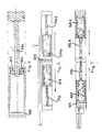
- Figure 3 shows the system in the fired or uncocked state.
- the piston 128 is in the forward position and the volume of compression chamber 125 is at a minimum.
- Figure 4 shows the same embodiment in the cocked position in which the piston 128 is held in its rearmost position by a trigger mechanism 160. The differences between the embodiment shown in Figure 1 and 2 and that shown in FIgures 3 and 4 will now become more apparent.
- the compression ratio achieved in the variable-volume sealed chamber will be the total of the volume 152 + 152A when the piston 128 is fully forward, divided by the reduced volume of 152 + 152A when the piston 128 is in the cocked position.
- the reduction in volume of space 152 during the cocking stroke is substantial, perhaps of the order of a half.
- the compression ratio will be approximately 3/2 or 1.5.
- Figures 3 and 4 show that a small diameter dummy piston 136 dramatically reduces the compression ratio, since the space 152 is only reduced during the cocking stroke by the volume of the dummy piston 136 which projects into space 152 by the end of the cocking stroke. In a preferred configuration as indicated in Figures 3 and 4, this compression ratio would be of the order of 1.1:1, although in practice a ratio of about 1.15:1 has also been found to be very satisfactory.
- This greatly reduced compression ratio has the effect of producing a corresponding reduction in the rate at which the cocking effort increases during the cocking stroke.
- Figure 5 shows a similar but alternative embodiment which employs a small diameter, solid dummy piston 236.
- the rear of the piston 228 is open, allowing access to the collar 227 in which a charging valve 250 is mounted. This will have the effect of increasing the compression ratio slightly, while still keeping a low frictional drag from the O-rings.
- the remainder of the arrangement has been omitted from the drawing for clarity but is similar to the previously described constructions.
- Figures 6 and 7 show the invention applied in two "contra-piston" embodiments in which there are two pistons which travel in opposite directions on firing and which represent a means of counteracting recoil (see GB-B-2,149,483 for earlier work in this area).
- the two pistons 328,328A are forced away from each other during the cocking stroke. When the weapon is fired, they move rapidly towards one another, compressing the air between them and forcing it out of a radial transfer port 324 and into the barrel.
- the two dummy pistons 336,336A are shown as solid, but could be hollow.
- pistons 428,428A are forced together during the cocking stroke and fly apart when fired.
- the left-hand piston 428 in the drawing does useful work by compressing the air in the compression chamber 425 and forcing it down the barrel while the right hand piston 428A is simply a counter-weight, intended to reduce any movement of the weapon to a minimum during the firing stroke.
- the two dummy pistons 436,436A are shown as solid but could be hollow. They are fixed to a central support.
Landscapes
- Engineering & Computer Science (AREA)
- General Engineering & Computer Science (AREA)
- Toys (AREA)
Applications Claiming Priority (2)
| Application Number | Priority Date | Filing Date | Title |
|---|---|---|---|
| GB9012829 | 1990-06-08 | ||
| GB909012829A GB9012829D0 (en) | 1990-06-08 | 1990-06-08 | Reduced diameter dummy piston |
Publications (3)
| Publication Number | Publication Date |
|---|---|
| EP0460961A2 true EP0460961A2 (fr) | 1991-12-11 |
| EP0460961A3 EP0460961A3 (en) | 1993-09-15 |
| EP0460961B1 EP0460961B1 (fr) | 1997-09-03 |
Family
ID=10677304
Family Applications (1)
| Application Number | Title | Priority Date | Filing Date |
|---|---|---|---|
| EP91305133A Expired - Lifetime EP0460961B1 (fr) | 1990-06-08 | 1991-06-07 | Arme de tir à air comprimé avec ressort à gaz |
Country Status (4)
| Country | Link |
|---|---|
| US (1) | US5193517A (fr) |
| EP (1) | EP0460961B1 (fr) |
| DE (1) | DE69127507T2 (fr) |
| GB (1) | GB9012829D0 (fr) |
Cited By (4)
| Publication number | Priority date | Publication date | Assignee | Title |
|---|---|---|---|---|
| WO1997021975A1 (fr) * | 1995-12-13 | 1997-06-19 | Frantisek Vacek | Arme a air comprime avec un piston actionne par un gaz |
| EP2955471A1 (fr) * | 2014-06-09 | 2015-12-16 | Thomas Gore | Pistolet à air avec ensemble de ressort à gaz |
| US9404707B2 (en) | 2014-06-09 | 2016-08-02 | Thomas Gore | Air gun with gas spring assembly |
| RU2755926C2 (ru) * | 2019-10-28 | 2021-09-23 | Григорий Витальевич Челышев | Пневматическая мультикомпрессионная винтовка Челышева Г.В. |
Families Citing this family (37)
| Publication number | Priority date | Publication date | Assignee | Title |
|---|---|---|---|---|
| ATE197904T1 (de) * | 1993-07-31 | 2000-12-15 | Weston Medical Ltd | Nadelloser injektor |
| US5570676A (en) * | 1994-02-04 | 1996-11-05 | Gore; Thomas D. | Method for converting a mechanical spring gun to a pneumatic spring gun and the resulting pneumatic spring gun |
| US5599302A (en) * | 1995-01-09 | 1997-02-04 | Medi-Ject Corporation | Medical injection system and method, gas spring thereof and launching device using gas spring |
| US5865795A (en) | 1996-02-29 | 1999-02-02 | Medi-Ject Corporation | Safety mechanism for injection devices |
| US5800388A (en) | 1996-02-29 | 1998-09-01 | Medi-Ject Corporation | Plunger/ram assembly adapted for a fluid injector |
| US5921967A (en) | 1996-02-29 | 1999-07-13 | Medi-Ject Corporation | Plunger for nozzle assembly |
| US5697917A (en) | 1996-02-29 | 1997-12-16 | Medi-Ject Corporation | Nozzle assembly with adjustable plunger travel gap |
| US5643211A (en) | 1996-02-29 | 1997-07-01 | Medi-Ject Corporation | Nozzle assembly having a frangible plunger |
| US5722953A (en) | 1996-02-29 | 1998-03-03 | Medi-Ject Corporation | Nozzle assembly for injection device |
| US5769138A (en) * | 1996-04-01 | 1998-06-23 | Medi-Ject Corporation | Nozzle and adapter for loading medicament into an injector |
| US5875976A (en) | 1996-12-24 | 1999-03-02 | Medi-Ject Corporation | Locking mechanism for nozzle assembly |
| AUPP204598A0 (en) * | 1998-02-26 | 1998-03-19 | Horlock, Nicolas James | Pneumatic spear gun with pressure intensifying hand water pump |
| US6076513A (en) * | 1998-07-01 | 2000-06-20 | Hasbro, Inc. | Trigger operated bow type toy gun |
| US6125834A (en) * | 1999-01-25 | 2000-10-03 | Brookhaven Science Associates | Free-piston cutting machine |
| ES2194564B2 (es) * | 2000-10-13 | 2005-07-16 | Industrias El Gamo, S.A. | Dispositivo de articulacion de un cañon en una carabina o pistola de aire comprimido de cañon basculante. |
| US6581585B2 (en) * | 2001-11-16 | 2003-06-24 | Alfred F. Nibecker, Jr. | Air gun |
| ATE292780T1 (de) * | 2002-03-01 | 2005-04-15 | Contraves Ag | Federvorrichtung für feuerwaffe und feuerwaffe |
| US7410124B2 (en) * | 2003-02-21 | 2008-08-12 | Aai Corporation | Lightweight air vehicle and pneumatic launcher |
| US7222573B2 (en) * | 2005-04-01 | 2007-05-29 | Pontieri James M | Aerodynamic air gun projectile |
| DE102006003510A1 (de) * | 2006-01-24 | 2007-07-26 | Oerlikon Contraves Ag | Gasfeder für eine Revolver- oder Verschlusskanone |
| US20090084371A1 (en) * | 2007-10-01 | 2009-04-02 | Nibecker Jr Alfred F | Pneumatic device |
| US7854221B1 (en) * | 2008-08-20 | 2010-12-21 | Gore Thomas D | Air gun vibration damper and method |
| US8132563B2 (en) * | 2009-07-24 | 2012-03-13 | Thomas Gore | Gas spring assembly for an air gun |
| JP5865247B2 (ja) | 2009-09-09 | 2016-02-17 | エアロバイロメント, インコーポレイテッドAerovironment, Inc. | 可搬型rf透過性発射筒を有する遠隔操作無人航空機レポート抑制発射機のためのシステムおよび装置 |
| JP6243410B2 (ja) * | 2012-06-07 | 2017-12-06 | エアロバイロメント, インコーポレイテッドAerovironment, Inc. | 発射管内で無人航空機を脱着可能に連結するシステム |
| TWM473505U (zh) * | 2013-04-15 | 2014-03-01 | Guay Guay Trading Co Ltd | 玩具槍壓差式推彈結構 |
| US9982962B2 (en) | 2015-09-25 | 2018-05-29 | Sig Sauer, Inc. | Air gun with multiple energy sources |
| US10473805B2 (en) * | 2016-06-09 | 2019-11-12 | Sercel | Compensator block for marine seismic source and method |
| WO2018022428A1 (fr) * | 2016-07-27 | 2018-02-01 | Crosman Corporation | Pistolet à air comprimé à canon pliant ayant un véhicule actif |
| US10030933B2 (en) * | 2016-08-25 | 2018-07-24 | Thomas Gore Living Trust | Gas spring assembly and a catch therefor |
| US20190195594A1 (en) * | 2016-11-30 | 2019-06-27 | Umarex Usa, Inc. | Cocking and Loading Apparatus for Repeater Air Rifle |
| US10267593B2 (en) * | 2016-11-30 | 2019-04-23 | Umarex Usa, Inc. | Cocking and loading apparatus for repeater air rifle |
| US10197355B2 (en) * | 2016-11-30 | 2019-02-05 | Umarex Usa, Inc. | Cocking and loading apparatus for repeater air rifle |
| US12025403B2 (en) * | 2020-04-14 | 2024-07-02 | Easebon Services Limited | Toy fluid launcher and method of using same |
| US11118858B1 (en) | 2020-08-18 | 2021-09-14 | Joshua Charles Harrison | Spring-piston air gun with reliable cocked indicator |
| US20240418475A1 (en) * | 2023-06-19 | 2024-12-19 | Banza Stamping Industry Corp | Pressurized gas vessel and piercing mechanism |
| US12474138B2 (en) * | 2023-06-19 | 2025-11-18 | Banza Stamping Industry Corporation | Spring-loaded piercing mechanism for a pressurized gas vessel |
Citations (5)
| Publication number | Priority date | Publication date | Assignee | Title |
|---|---|---|---|---|
| DE1553962B1 (de) | 1966-04-26 | 1971-06-24 | Stabilus Ind Und Handelsgmbh | Luftdruckschusswaffe |
| GB2084704B (en) | 1980-10-01 | 1983-06-29 | Theobald David Reginald | Air rifle |
| GB2149483A (en) | 1983-09-24 | 1985-06-12 | Utec Bv | Air weapons |
| US4771758A (en) | 1985-04-01 | 1988-09-20 | Utec B.V. | Air weapon with air compression system having grooves for air transfer |
| US4850329A (en) | 1987-01-09 | 1989-07-25 | Utec B.V. | Firing mechanisms for air weapons |
Family Cites Families (7)
| Publication number | Priority date | Publication date | Assignee | Title |
|---|---|---|---|---|
| US2101198A (en) * | 1936-06-12 | 1937-12-07 | William C Robinson | Air gun |
| US2145277A (en) * | 1937-08-18 | 1939-01-31 | Reardon Robert Edwin | Play gun |
| US2652821A (en) * | 1944-12-28 | 1953-09-22 | Bendix Westinghouse Automotive | Fluid pressure operated gun |
| SU469875A1 (ru) * | 1973-07-09 | 1975-05-05 | Предприятие П/Я Г-4406 | Метательный механизм пневматического оружи |
| GB2110348A (en) * | 1981-09-11 | 1983-06-15 | Sterling Armament Co Ltd | Improvements in or relating to air rifles |
| SU1126806A1 (ru) * | 1983-01-06 | 1984-11-30 | Предприятие П/Я Г-4406 | Пневматическое оружие |
| GB2181524B (en) * | 1985-10-14 | 1989-02-08 | Roy Hutchison | Spring piston air weapon |
-
1990
- 1990-06-08 GB GB909012829A patent/GB9012829D0/en active Pending
-
1991
- 1991-06-07 EP EP91305133A patent/EP0460961B1/fr not_active Expired - Lifetime
- 1991-06-07 DE DE69127507T patent/DE69127507T2/de not_active Expired - Lifetime
- 1991-06-10 US US07/713,439 patent/US5193517A/en not_active Expired - Lifetime
Patent Citations (5)
| Publication number | Priority date | Publication date | Assignee | Title |
|---|---|---|---|---|
| DE1553962B1 (de) | 1966-04-26 | 1971-06-24 | Stabilus Ind Und Handelsgmbh | Luftdruckschusswaffe |
| GB2084704B (en) | 1980-10-01 | 1983-06-29 | Theobald David Reginald | Air rifle |
| GB2149483A (en) | 1983-09-24 | 1985-06-12 | Utec Bv | Air weapons |
| US4771758A (en) | 1985-04-01 | 1988-09-20 | Utec B.V. | Air weapon with air compression system having grooves for air transfer |
| US4850329A (en) | 1987-01-09 | 1989-07-25 | Utec B.V. | Firing mechanisms for air weapons |
Cited By (4)
| Publication number | Priority date | Publication date | Assignee | Title |
|---|---|---|---|---|
| WO1997021975A1 (fr) * | 1995-12-13 | 1997-06-19 | Frantisek Vacek | Arme a air comprime avec un piston actionne par un gaz |
| EP2955471A1 (fr) * | 2014-06-09 | 2015-12-16 | Thomas Gore | Pistolet à air avec ensemble de ressort à gaz |
| US9404707B2 (en) | 2014-06-09 | 2016-08-02 | Thomas Gore | Air gun with gas spring assembly |
| RU2755926C2 (ru) * | 2019-10-28 | 2021-09-23 | Григорий Витальевич Челышев | Пневматическая мультикомпрессионная винтовка Челышева Г.В. |
Also Published As
| Publication number | Publication date |
|---|---|
| DE69127507T2 (de) | 1998-01-08 |
| EP0460961A3 (en) | 1993-09-15 |
| GB9012829D0 (en) | 1990-08-01 |
| DE69127507D1 (de) | 1997-10-09 |
| EP0460961B1 (fr) | 1997-09-03 |
| US5193517A (en) | 1993-03-16 |
Similar Documents
| Publication | Publication Date | Title |
|---|---|---|
| EP0460961B1 (fr) | Arme de tir à air comprimé avec ressort à gaz | |
| US6668478B2 (en) | Firearm pneumatic counter-recoil modulator & airgun thrust-adjustor | |
| US6901689B1 (en) | Firearm pneumatic counter-recoil modulator and airgun thrust-adjustor | |
| US5123329A (en) | Self-actuating blow forward firearm | |
| US4709686A (en) | Air weapon with gas-tight expansion chamber | |
| US3204625A (en) | Gas-operated pistol | |
| US2147003A (en) | Machine gun | |
| EP0244467B1 (fr) | Pistolet a air | |
| US4850329A (en) | Firing mechanisms for air weapons | |
| US3650177A (en) | Device for controlling the firing frequency in automatic firearms | |
| EP0022335A1 (fr) | Système de récupération de l'énergie de recul, par ex. pour tubes de canon | |
| US4745841A (en) | Liquid propellant gun | |
| US20110296977A1 (en) | Inner-ballistic for recoilless weapon | |
| US4693165A (en) | Liquid propellant gun | |
| US3212490A (en) | Air gun | |
| US4572152A (en) | Air guns with floating piston received in compensating chamber which is formed in main piston | |
| US20110168007A1 (en) | Conversion kit with recoil delay action and method for transformation of c1 howitzer in a more performent c-3 model | |
| US6739324B2 (en) | Compressed air distributor | |
| US3599530A (en) | Automatic replenisher for the hydro-pneumatic recoil systems of large caliber guns | |
| US3502061A (en) | Gas gun having removable rotatable magazine | |
| RU2134859C1 (ru) | Гидропневматическое ружье для подводной охоты | |
| GB2149483A (en) | Air weapons | |
| RU2230275C1 (ru) | Маркер пневматический, автоматический | |
| William et al. | Design of 120 mm Recoiling Mortar System | |
| RU2741145C1 (ru) | Механизм перезаряжания устройства для стрельбы или имитации стрельбы |
Legal Events
| Date | Code | Title | Description |
|---|---|---|---|
| PUAI | Public reference made under article 153(3) epc to a published international application that has entered the european phase |
Free format text: ORIGINAL CODE: 0009012 |
|
| AK | Designated contracting states |
Kind code of ref document: A2 Designated state(s): DE ES GB IT |
|
| PUAL | Search report despatched |
Free format text: ORIGINAL CODE: 0009013 |
|
| AK | Designated contracting states |
Kind code of ref document: A3 Designated state(s): DE ES GB IT |
|
| 17P | Request for examination filed |
Effective date: 19940315 |
|
| 17Q | First examination report despatched |
Effective date: 19950623 |
|
| GRAG | Despatch of communication of intention to grant |
Free format text: ORIGINAL CODE: EPIDOS AGRA |
|
| GRAH | Despatch of communication of intention to grant a patent |
Free format text: ORIGINAL CODE: EPIDOS IGRA |
|
| RAP1 | Party data changed (applicant data changed or rights of an application transferred) |
Owner name: TAYLOR, HUGH FRANCIS Owner name: THEOBALD, DAVID REGINALD |
|
| RIN1 | Information on inventor provided before grant (corrected) |
Inventor name: TAYLOR, HUGH FRANCIS Inventor name: THEOBALD, DAVID REGINALD |
|
| GRAH | Despatch of communication of intention to grant a patent |
Free format text: ORIGINAL CODE: EPIDOS IGRA |
|
| GRAA | (expected) grant |
Free format text: ORIGINAL CODE: 0009210 |
|
| AK | Designated contracting states |
Kind code of ref document: B1 Designated state(s): DE ES GB IT |
|
| PG25 | Lapsed in a contracting state [announced via postgrant information from national office to epo] |
Ref country code: IT Free format text: LAPSE BECAUSE OF FAILURE TO SUBMIT A TRANSLATION OF THE DESCRIPTION OR TO PAY THE FEE WITHIN THE PRE;WARNING: LAPSES OF ITALIAN PATENTS WITH EFFECTIVE DATE BEFORE 2007 MAY HAVE OCCURRED AT ANY TIME BEFORE 2007. THE CORRECT EFFECTIVE DATE MAY BE DIFFERENT FROM THE ONE RECORDED.SCRIBED TIME-LIMIT Effective date: 19970903 Ref country code: ES Free format text: THE PATENT HAS BEEN ANNULLED BY A DECISION OF A NATIONAL AUTHORITY Effective date: 19970903 |
|
| REF | Corresponds to: |
Ref document number: 69127507 Country of ref document: DE Date of ref document: 19971009 |
|
| PLBE | No opposition filed within time limit |
Free format text: ORIGINAL CODE: 0009261 |
|
| STAA | Information on the status of an ep patent application or granted ep patent |
Free format text: STATUS: NO OPPOSITION FILED WITHIN TIME LIMIT |
|
| 26N | No opposition filed | ||
| REG | Reference to a national code |
Ref country code: GB Ref legal event code: IF02 |
|
| REG | Reference to a national code |
Ref country code: GB Ref legal event code: 732E |
|
| PGFP | Annual fee paid to national office [announced via postgrant information from national office to epo] |
Ref country code: DE Payment date: 20100625 Year of fee payment: 20 Ref country code: GB Payment date: 20100401 Year of fee payment: 20 |
|
| REG | Reference to a national code |
Ref country code: DE Ref legal event code: R071 Ref document number: 69127507 Country of ref document: DE |
|
| REG | Reference to a national code |
Ref country code: DE Ref legal event code: R071 Ref document number: 69127507 Country of ref document: DE |
|
| REG | Reference to a national code |
Ref country code: GB Ref legal event code: PE20 Expiry date: 20110606 |
|
| PG25 | Lapsed in a contracting state [announced via postgrant information from national office to epo] |
Ref country code: GB Free format text: LAPSE BECAUSE OF EXPIRATION OF PROTECTION Effective date: 20110606 |
|
| PG25 | Lapsed in a contracting state [announced via postgrant information from national office to epo] |
Ref country code: DE Free format text: LAPSE BECAUSE OF EXPIRATION OF PROTECTION Effective date: 20110608 |