EP0461018B1 - Verfahren und Vorrichtung zur Kontrolle der Dicke und der Kohäsion der Verbindung eines Duplexrohrs - Google Patents
Verfahren und Vorrichtung zur Kontrolle der Dicke und der Kohäsion der Verbindung eines Duplexrohrs Download PDFInfo
- Publication number
- EP0461018B1 EP0461018B1 EP91401439A EP91401439A EP0461018B1 EP 0461018 B1 EP0461018 B1 EP 0461018B1 EP 91401439 A EP91401439 A EP 91401439A EP 91401439 A EP91401439 A EP 91401439A EP 0461018 B1 EP0461018 B1 EP 0461018B1
- Authority
- EP
- European Patent Office
- Prior art keywords
- tube
- thickness
- core
- interface
- cladding
- Prior art date
- Legal status (The legal status is an assumption and is not a legal conclusion. Google has not performed a legal analysis and makes no representation as to the accuracy of the status listed.)
- Expired - Lifetime
Links
- 238000000034 method Methods 0.000 title claims description 47
- 238000005253 cladding Methods 0.000 claims description 53
- 229910045601 alloy Inorganic materials 0.000 claims description 27
- 239000000956 alloy Substances 0.000 claims description 27
- 229910001093 Zr alloy Inorganic materials 0.000 claims description 21
- 238000005259 measurement Methods 0.000 claims description 21
- 239000000463 material Substances 0.000 claims description 18
- 230000005284 excitation Effects 0.000 claims description 11
- 238000012545 processing Methods 0.000 claims description 11
- 239000010953 base metal Substances 0.000 claims description 6
- 230000006698 induction Effects 0.000 claims description 6
- 238000002604 ultrasonography Methods 0.000 claims description 5
- 230000035945 sensitivity Effects 0.000 claims description 3
- 238000004804 winding Methods 0.000 claims description 3
- 238000006073 displacement reaction Methods 0.000 claims description 2
- 230000000295 complement effect Effects 0.000 claims 4
- 230000008034 disappearance Effects 0.000 claims 1
- 230000000644 propagated effect Effects 0.000 claims 1
- 230000003313 weakening effect Effects 0.000 claims 1
- 239000010410 layer Substances 0.000 description 44
- 238000007747 plating Methods 0.000 description 39
- 230000007547 defect Effects 0.000 description 24
- 239000011248 coating agent Substances 0.000 description 16
- 238000000576 coating method Methods 0.000 description 16
- 239000000523 sample Substances 0.000 description 16
- 239000000446 fuel Substances 0.000 description 14
- 238000001514 detection method Methods 0.000 description 11
- XEEYBQQBJWHFJM-UHFFFAOYSA-N Iron Chemical compound [Fe] XEEYBQQBJWHFJM-UHFFFAOYSA-N 0.000 description 8
- 239000000203 mixture Substances 0.000 description 8
- 230000005540 biological transmission Effects 0.000 description 7
- ATJFFYVFTNAWJD-UHFFFAOYSA-N Tin Chemical compound [Sn] ATJFFYVFTNAWJD-UHFFFAOYSA-N 0.000 description 5
- QCWXUUIWCKQGHC-UHFFFAOYSA-N Zirconium Chemical compound [Zr] QCWXUUIWCKQGHC-UHFFFAOYSA-N 0.000 description 5
- 239000011247 coating layer Substances 0.000 description 5
- 239000011135 tin Substances 0.000 description 5
- 229910052718 tin Inorganic materials 0.000 description 5
- 229910052726 zirconium Inorganic materials 0.000 description 5
- 238000004458 analytical method Methods 0.000 description 4
- 230000000694 effects Effects 0.000 description 4
- 229910052742 iron Inorganic materials 0.000 description 4
- 238000000691 measurement method Methods 0.000 description 4
- 230000008569 process Effects 0.000 description 4
- 239000002344 surface layer Substances 0.000 description 4
- 230000002123 temporal effect Effects 0.000 description 4
- 238000005275 alloying Methods 0.000 description 3
- 230000000712 assembly Effects 0.000 description 3
- 238000000429 assembly Methods 0.000 description 3
- 230000007797 corrosion Effects 0.000 description 3
- 238000005260 corrosion Methods 0.000 description 3
- 238000002592 echocardiography Methods 0.000 description 3
- 229910052758 niobium Inorganic materials 0.000 description 3
- 239000010955 niobium Substances 0.000 description 3
- GUCVJGMIXFAOAE-UHFFFAOYSA-N niobium atom Chemical compound [Nb] GUCVJGMIXFAOAE-UHFFFAOYSA-N 0.000 description 3
- 229910052720 vanadium Inorganic materials 0.000 description 3
- LEONUFNNVUYDNQ-UHFFFAOYSA-N vanadium atom Chemical compound [V] LEONUFNNVUYDNQ-UHFFFAOYSA-N 0.000 description 3
- XLYOFNOQVPJJNP-UHFFFAOYSA-N water Substances O XLYOFNOQVPJJNP-UHFFFAOYSA-N 0.000 description 3
- RYGMFSIKBFXOCR-UHFFFAOYSA-N Copper Chemical compound [Cu] RYGMFSIKBFXOCR-UHFFFAOYSA-N 0.000 description 2
- 230000008901 benefit Effects 0.000 description 2
- 238000004364 calculation method Methods 0.000 description 2
- 229910052802 copper Inorganic materials 0.000 description 2
- 239000010949 copper Substances 0.000 description 2
- 230000008878 coupling Effects 0.000 description 2
- 238000010168 coupling process Methods 0.000 description 2
- 238000005859 coupling reaction Methods 0.000 description 2
- 239000007788 liquid Substances 0.000 description 2
- 229910052751 metal Inorganic materials 0.000 description 2
- 239000002184 metal Substances 0.000 description 2
- BASFCYQUMIYNBI-UHFFFAOYSA-N platinum Chemical compound [Pt] BASFCYQUMIYNBI-UHFFFAOYSA-N 0.000 description 2
- 238000012360 testing method Methods 0.000 description 2
- VYZAMTAEIAYCRO-UHFFFAOYSA-N Chromium Chemical compound [Cr] VYZAMTAEIAYCRO-UHFFFAOYSA-N 0.000 description 1
- 229910052778 Plutonium Inorganic materials 0.000 description 1
- WZECUPJJEIXUKY-UHFFFAOYSA-N [O-2].[O-2].[O-2].[U+6] Chemical compound [O-2].[O-2].[O-2].[U+6] WZECUPJJEIXUKY-UHFFFAOYSA-N 0.000 description 1
- 230000003321 amplification Effects 0.000 description 1
- 230000002238 attenuated effect Effects 0.000 description 1
- 238000005452 bending Methods 0.000 description 1
- 238000005266 casting Methods 0.000 description 1
- 229910052804 chromium Inorganic materials 0.000 description 1
- 239000011651 chromium Substances 0.000 description 1
- 238000007796 conventional method Methods 0.000 description 1
- 238000010586 diagram Methods 0.000 description 1
- 238000007688 edging Methods 0.000 description 1
- 238000001125 extrusion Methods 0.000 description 1
- 239000012530 fluid Substances 0.000 description 1
- 230000036541 health Effects 0.000 description 1
- 238000007689 inspection Methods 0.000 description 1
- 238000004519 manufacturing process Methods 0.000 description 1
- 238000012986 modification Methods 0.000 description 1
- 230000004048 modification Effects 0.000 description 1
- 238000003199 nucleic acid amplification method Methods 0.000 description 1
- 244000045947 parasite Species 0.000 description 1
- 239000008188 pellet Substances 0.000 description 1
- 229910052697 platinum Inorganic materials 0.000 description 1
- OYEHPCDNVJXUIW-UHFFFAOYSA-N plutonium atom Chemical compound [Pu] OYEHPCDNVJXUIW-UHFFFAOYSA-N 0.000 description 1
- 230000001902 propagating effect Effects 0.000 description 1
- 238000005096 rolling process Methods 0.000 description 1
- 229910000439 uranium oxide Inorganic materials 0.000 description 1
- 238000012800 visualization Methods 0.000 description 1
Images


Classifications
-
- G—PHYSICS
- G01—MEASURING; TESTING
- G01N—INVESTIGATING OR ANALYSING MATERIALS BY DETERMINING THEIR CHEMICAL OR PHYSICAL PROPERTIES
- G01N27/00—Investigating or analysing materials by the use of electric, electrochemical, or magnetic means
- G01N27/72—Investigating or analysing materials by the use of electric, electrochemical, or magnetic means by investigating magnetic variables
-
- G—PHYSICS
- G01—MEASURING; TESTING
- G01B—MEASURING LENGTH, THICKNESS OR SIMILAR LINEAR DIMENSIONS; MEASURING ANGLES; MEASURING AREAS; MEASURING IRREGULARITIES OF SURFACES OR CONTOURS
- G01B5/00—Measuring arrangements characterised by the use of mechanical techniques
- G01B5/02—Measuring arrangements characterised by the use of mechanical techniques for measuring length, width or thickness
-
- G—PHYSICS
- G01—MEASURING; TESTING
- G01B—MEASURING LENGTH, THICKNESS OR SIMILAR LINEAR DIMENSIONS; MEASURING ANGLES; MEASURING AREAS; MEASURING IRREGULARITIES OF SURFACES OR CONTOURS
- G01B17/00—Measuring arrangements characterised by the use of infrasonic, sonic or ultrasonic vibrations
- G01B17/02—Measuring arrangements characterised by the use of infrasonic, sonic or ultrasonic vibrations for measuring thickness
- G01B17/025—Measuring arrangements characterised by the use of infrasonic, sonic or ultrasonic vibrations for measuring thickness for measuring thickness of coating
-
- G—PHYSICS
- G01—MEASURING; TESTING
- G01N—INVESTIGATING OR ANALYSING MATERIALS BY DETERMINING THEIR CHEMICAL OR PHYSICAL PROPERTIES
- G01N29/00—Investigating or analysing materials by the use of ultrasonic, sonic or infrasonic waves; Visualisation of the interior of objects by transmitting ultrasonic or sonic waves through the object
- G01N29/04—Analysing solids
- G01N29/11—Analysing solids by measuring attenuation of acoustic waves
-
- G—PHYSICS
- G01—MEASURING; TESTING
- G01N—INVESTIGATING OR ANALYSING MATERIALS BY DETERMINING THEIR CHEMICAL OR PHYSICAL PROPERTIES
- G01N29/00—Investigating or analysing materials by the use of ultrasonic, sonic or infrasonic waves; Visualisation of the interior of objects by transmitting ultrasonic or sonic waves through the object
- G01N29/22—Details, e.g. general constructional or apparatus details
- G01N29/221—Arrangements for directing or focusing the acoustical waves
-
- G—PHYSICS
- G01—MEASURING; TESTING
- G01N—INVESTIGATING OR ANALYSING MATERIALS BY DETERMINING THEIR CHEMICAL OR PHYSICAL PROPERTIES
- G01N29/00—Investigating or analysing materials by the use of ultrasonic, sonic or infrasonic waves; Visualisation of the interior of objects by transmitting ultrasonic or sonic waves through the object
- G01N29/22—Details, e.g. general constructional or apparatus details
- G01N29/24—Probes
- G01N29/2456—Focusing probes
-
- G—PHYSICS
- G01—MEASURING; TESTING
- G01N—INVESTIGATING OR ANALYSING MATERIALS BY DETERMINING THEIR CHEMICAL OR PHYSICAL PROPERTIES
- G01N2291/00—Indexing codes associated with group G01N29/00
- G01N2291/02—Indexing codes associated with the analysed material
- G01N2291/023—Solids
- G01N2291/0231—Composite or layered materials
-
- G—PHYSICS
- G01—MEASURING; TESTING
- G01N—INVESTIGATING OR ANALYSING MATERIALS BY DETERMINING THEIR CHEMICAL OR PHYSICAL PROPERTIES
- G01N2291/00—Indexing codes associated with group G01N29/00
- G01N2291/02—Indexing codes associated with the analysed material
- G01N2291/028—Material parameters
- G01N2291/02854—Length, thickness
-
- G—PHYSICS
- G01—MEASURING; TESTING
- G01N—INVESTIGATING OR ANALYSING MATERIALS BY DETERMINING THEIR CHEMICAL OR PHYSICAL PROPERTIES
- G01N2291/00—Indexing codes associated with group G01N29/00
- G01N2291/02—Indexing codes associated with the analysed material
- G01N2291/028—Material parameters
- G01N2291/02863—Electric or magnetic parameters
-
- G—PHYSICS
- G01—MEASURING; TESTING
- G01N—INVESTIGATING OR ANALYSING MATERIALS BY DETERMINING THEIR CHEMICAL OR PHYSICAL PROPERTIES
- G01N2291/00—Indexing codes associated with group G01N29/00
- G01N2291/02—Indexing codes associated with the analysed material
- G01N2291/028—Material parameters
- G01N2291/02881—Temperature
-
- G—PHYSICS
- G01—MEASURING; TESTING
- G01N—INVESTIGATING OR ANALYSING MATERIALS BY DETERMINING THEIR CHEMICAL OR PHYSICAL PROPERTIES
- G01N2291/00—Indexing codes associated with group G01N29/00
- G01N2291/04—Wave modes and trajectories
- G01N2291/042—Wave modes
- G01N2291/0421—Longitudinal waves
-
- G—PHYSICS
- G01—MEASURING; TESTING
- G01N—INVESTIGATING OR ANALYSING MATERIALS BY DETERMINING THEIR CHEMICAL OR PHYSICAL PROPERTIES
- G01N2291/00—Indexing codes associated with group G01N29/00
- G01N2291/04—Wave modes and trajectories
- G01N2291/044—Internal reflections (echoes), e.g. on walls or defects
-
- G—PHYSICS
- G01—MEASURING; TESTING
- G01N—INVESTIGATING OR ANALYSING MATERIALS BY DETERMINING THEIR CHEMICAL OR PHYSICAL PROPERTIES
- G01N2291/00—Indexing codes associated with group G01N29/00
- G01N2291/04—Wave modes and trajectories
- G01N2291/048—Transmission, i.e. analysed material between transmitter and receiver
-
- G—PHYSICS
- G01—MEASURING; TESTING
- G01N—INVESTIGATING OR ANALYSING MATERIALS BY DETERMINING THEIR CHEMICAL OR PHYSICAL PROPERTIES
- G01N2291/00—Indexing codes associated with group G01N29/00
- G01N2291/10—Number of transducers
- G01N2291/101—Number of transducers one transducer
-
- G—PHYSICS
- G01—MEASURING; TESTING
- G01N—INVESTIGATING OR ANALYSING MATERIALS BY DETERMINING THEIR CHEMICAL OR PHYSICAL PROPERTIES
- G01N2291/00—Indexing codes associated with group G01N29/00
- G01N2291/26—Scanned objects
- G01N2291/263—Surfaces
- G01N2291/2634—Surfaces cylindrical from outside
Definitions
- the invention relates to a method and a device for controlling the thickness and cohesion of the interface of a duplex tube and in particular of a zirconium alloy duplex tube used as a cladding element of a fuel rod. an assembly for a water-cooled nuclear reactor.
- the fuel assemblies of water-cooled nuclear reactors and in particular of pressurized water nuclear reactors comprise a framework in which are inserted fuel rods constituted by a sheath containing a nuclear combustible material such as uranium oxide or plutonium in the form of sintered pellets.
- the sheath produced from a zirconium alloy tube must have good resistance to corrosion under the effect of the primary fluid in circulation in contact with the outer surface of the sheath.
- the zirconium alloy constituting the plating or coating layer is different from the alloy constituting the core of the tube and contains iron as well as at least one of the vanadium, platinum and copper elements.
- This surface layer the thickness of which represents 5 to 20% of the total thickness of the wall of the sheath, can be produced by extrusion of a blank formed by an inner tube made of zirconium alloy of conventional composition on which is threaded. an outer tube having the composition of the surface layer.
- the sheath is then rolled on a mit step rolling mill to its final diameter.
- a duplex tube whose surface layer having a thickness of between 10 and 25% of the he total thickness of the sheath wall consists of a zirconium-based alloy containing tin, iron and niobium or vanadium.
- the tubular core of the duplex tube can be made of a conventional zirconium alloy in the case of the production of sheaths for fuel rods or of a zirconium-based alloy mainly containing niobium as an alloying element.
- duplex tubes which are intended to constitute sheaths for fuel rods, in particular as regards the diameter of the tube, the total thickness of the sheath, l thickness of the outer plating layer and the cohesion of the interface zone between the clad layer and the core of the tube.
- the control of the diameter and of the total thickness of the sheath can be carried out using a conventional technique consisting in measuring the difference of the propagation times of ultrasonic waves, of impulse shape, which are reflected by the external surface and by the surface internal of the tube.
- This ultrasonic control and measurement technique known as the "pulse-echo" technique is possibly adapted to take account of the cladding layer, in calculating the total thickness of the sheath.
- This improved technique does not, however, allow plating thicknesses of less than 0.4 mm to be measured, since the industrial implementation of the process under satisfactory conditions requires the use of ultrasonic waves whose frequency does not exceed 20 MHz.
- the cladding layer and the tubular core of the duplex tube consist of very low alloyed zirconium alloys which have very similar acoustic properties, so that the reflection coefficient of the acoustic waves at the plating-core interface is very low (generally less than 2%) .
- the interface echo is then very weak and is embedded in the acoustic and electronic noise of the ultrasonic signal.
- FR-A-2,534,015 has proposed a method and a measuring device making it possible to determine the thickness of a zirconium coating on a zirconium alloy tube implementing the analysis and measurement of induced currents in the plating layer of the duplex tube, by magnetic induction, using an excitation current the frequency of which is chosen as a function of the nominal thickness of the plating or coating layer of the tube.
- the selected frequency and the processing of the signals corresponding to the induced currents also make it possible to eliminate, to a certain extent, the measurement errors resulting from a variation in the width of the air gap between the excitation coil and the wall of the tube.
- this technique does not make it possible to carry out alone a control of the total thickness of the tube and of the cohesion of the interface zone between the plating or coating layer of the tube and the tubular core.
- duplex tube generally designated by the reference 1 and comprising a tubular core 2 of a zirconium alloy covered externally by a cladding layer 3 of a second zirconium alloy whose composition is different from the composition of the alloy constituting the core 2.
- the zirconium alloys constituting the core 2 and the cladding layer 3 of the duplex tube 1 are low alloyed zirconium alloys whose contents of alloy elements are less than 1% by weight for each of these elements.
- the tubular core 2 and the cladding layer 3 therefore have acoustic properties which are extremely close to one another.
- the coating or plating layer 3 has a small thickness, generally between 60 and 80 f..lm, the metallic core 2 itself having a thickness slightly less than 600 f..lm.
- a duplex tube as shown in FIG. 1 used as the sheath of a fuel rod of an assembly of a pressurized water nuclear reactor generally has an outside diameter of the order of 10 mm and a length of the order 4 m.
- FIG 2A there is shown in section, the wall of a duplex tube as shown in Figure 1 comprising a tubular core 2 covered by a layer of cladding and coating bonded to the metal core, along a cylindrical surface interface 4.
- an ultrasonic transducer 5 is used emitting a beam of ultrasonic waves 6 towards the external surface of the duplex tube constituted by the outer surface of the plating layer 3.
- the tube 1 is immersed in a coupling medium constituted by a liquid allowing the transmission of the ultrasonic waves emitted by the transducer 5.
- a part of the beam of ultrasonic waves 6 is reflected by the external surface of the duplex tube in the form of a beam 6 'which is picked up by the transducer 5 and transformed into an electrical signal which is transmitted to a processing unit 7.
- the corresponding echo 8 can be viewed on an oscillogram giving an image of its amplitude and its position on the time scale.
- the ultrasonic beam 6'a transmitted through the wall of the duplex tube is reflected, in the form of a beam 6'a, by the inner surface of the core 2 of the duplex tube.
- the ultrasonic beam 6'a is picked up by the transducer 5 which transforms it into an electrical signal and allows, thanks to the processing module 7, its display on the oscillogram of FIG. 2B, in the form of the echo signal 8a.
- the time difference between signal 8 and signal 8a corresponds to twice the travel time ⁇ T of the ultrasonic waves through the wall of the tube 1.
- An approximate value of the total thickness eg of the sheath corresponding to the thickness of the wall of the duplex tube can be obtained by assuming that the propagation speeds of the ultrasonic waves in the metallic core of the sheath and in the layer of plating are identical.
- the method of direct measurement of the propagation time of ultrasonic waves does not make it possible to measure the thickness of the plating layer ep, the coefficient of reflection of the acoustic waves at the interface 4 between the plating layer 3 and the core 2 being very weak (generally less than 2%), owing to the fact that the acoustic properties of the materials constituting the cladding layer and the core are extremely close to one another.
- the plating layer has a small thickness compared to the total thickness of the wall, so that the differences in propagation time to be taken into account are themselves very small.
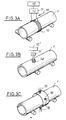
- FIGS. 3A, 3B and 3C three different embodiments are shown of an eddy current device making it possible to measure the thickness of an external cladding layer of a duplex tube 1 constituted by a metallic core covered by a plating layer, the metallic core and the plating layer being constituted by two zirconium alloys containing very small amounts of alloying elements.
- Zircaloy which is a zirconium alloy containing tin
- a variation of 1% in the tin content results in a variation of conductivity of the order of 50%.
- Such variations make it possible to apply the technique of induced currents or eddy currents to perform a thickness control of a plating layer whose composition is different from that of the metallic core coated by the plating layer.
- a coil 10 comprising a certain number of turns surrounding the tube 1.
- the coil is supplied by a multifrequency sinusoidal excitation current via a current source 11 connected to its terminals.
- the electrical signals corresponding to the induced currents are processed by a processing unit 12.
- the average value of the thickness of the cladding is measured, which includes the possible variations in thickness depending on the circumference of the tube or circumferential variations. Variations in thickness are also integrated along the length of the coil 10 or axial variations.
- the measurement is also sensitive to the centering of the tube inside the coil constituting the eddy current probe, so that this centering, even carried out in an optimized manner, risks reducing the accuracy of the measurement.
- a second measurement technique as shown in FIG. 3B consists in using a coil 14 whose axis has a radial direction relative to the tube 1.
- the device as shown in FIG. 3B makes it possible to carry out a local measurement of the thickness of the plating of the tube 1.
- FIG. 3C it is also possible to use several coils 15 similar to the coil 14 shown in FIG. 3B and fixed on a common support 16, so that the coils 15 whose axes have radial directions relative to to tube 1, are arranged around the tube, in regularly distributed circumferential positions.
- the frequency of the sinusoidal excitation signal as well as the dimensions of the windings (diameter and height) are determined so as to optimize the sensitivity of the measurements to variations in thickness of the cladding and to minimize the variations in the measurement signals due to variations in the distance between the coil and the surface of the tube, constituting an air gap.
- the method according to the invention is therefore characterized by the use of a multifrequency sinusoidal excitation signal comprising a main frequency as well as secondary frequencies.
- Two auxiliary frequencies can also be used, one of which is sensitive to the variation in conductivity of the base material constituting the core while being very insensitive to variations in the conductivity of the cladding as well as to the variations in thickness of the core. and of the cladding and the other of which is sensitive only to variations in conductivity of the cladding.
- the probe is simultaneously excited by each of the sinusoidal signals having the frequencies determined in the manner described above and the phase and amplitude measurement signals corresponding to each of the sinusoidal signals of determined frequency are digitized and processed, as indicated below. above, by a processing module and by computer means making it possible to deduce from these signals the value of the thickness of the cladding.
- the thickness of the plating is measured either by phase analysis of the signal corresponding to the eddy currents, this method presenting the advantage of being less sensitive to variations in lift-off, ie by a combined analysis of the phase and the amplitude of the signals corresponding to the eddy currents.
- e p / V p represents the travel time of the ultrasonic wave in the plating material
- (clair - e p / V p ) represents the travel time of the ultrasonic wave in the core of the tube
- (clair - e p / V p ) x Va represents the thickness of the core, for an axial position of the tube perfectly determined by means of control and measurement of axial position.
- the method according to the invention also allows detection of cohesion defects at the interface between the cladding and the core of the tube.
- Cohesion defects are flat, of negligible thickness and arranged parallel to the surface of the tube.
- An ultrasonic detection technique is therefore better suited, although the very shallow depth of the defect under the surface of the tube, corresponding to the thickness of the plating layer (between 80 and 100 ⁇ m) constitutes a difficulty in detecting cohesion defects at the interface.
- the main drawback of these reflection detection techniques lies in the need to use very high frequency ultrasound, for example at a frequency greater than 100 MHz, which corresponds to wavelengths in zirconium of less than 50 ⁇ m. .
- ultrasonic waves are emitted in directions that are substantially radial with respect to the tube, that is to say with a substantially normal incidence.
- FIG. 4A shows an ultrasonic beam 21 reflecting on the outside surface of the tube, an ultrasonic beam 22 reflecting on a defect 20 situated along the interface 4 between the cladding layer 3 and the core 2 of the tube and a beam 23 reflecting on the inner surface of the tube, the corresponding echoes 24, 25 and 26 being represented in FIG. 4B.
- the echo signal 26 reflected by the internal surface of the tube has a smaller amplitude compared to the signal 24 reflected by the external surface of the tube.
- the time difference between these two echoes corresponds to twice the travel time of the ultrasonic waves in the thickness of the tube.
- the echo signal 25 corresponding to a reflection on a fault 20 along the interface 4 has a smaller amplitude and a very small time offset with respect to the signal reflected on the outside surface of the tube, due to the very thin thickness of the layer 3 of plating.
- This first detection method is therefore limited by the fact that the defect is very close to the outer surface of the tube and therefore that the corresponding echo 25 can be mixed with the echo 24 which has a large temporal width due to the effects of the electronic amplification of the ultrasonic signal.
- a second method illustrated by FIGS. 5A and 5B consists in using a beam of ultrasonic waves 27 in oblique incidence so that this beam is first reflected by the internal surface of the tube, then by the defect 28 at the interface and a second time through the inner surface of the tube.
- the echo 29 corresponding to the re bending on the defect 28 after a first reflection on the internal surface of the tube followed by a second reflection on the internal surface of the tube has a significant time offset with respect to the echo 24.
- the echo 29 and the immediate next echo 29 ′ reflected by the internal surface of the tube are of small and equivalent amplitude and temporal width and are therefore easily separable.
- a third measurement method is illustrated in Figures 6A and 6B.
- the control is carried out from inside the tube and the ultrasonic beam is emitted at normal incidence so as to obtain a direct reflection on the fault 30.
- the echo 31 corresponding to the reflection on the defect 30 has a lesser amplitude and a significant time offset with respect to the signal reflected by the internal surface of the tube.
- this echo 31 and the immediate next echo 31 ′ resulting from the reflection on the external surface of the tube are of small and equivalent amplitudes and temporal widths and are therefore easily separable.
- FIGS. 7A, 7B, 8A and 8B illustrate a technique for detecting decohesion defects at the interface between the cladding layer 3 and the core 4 of a duplex tube 1, by transmission of an ultrasonic wave in the wall of the duplex tube constituting a fuel rod cladding, the ultrasonic wave then being reflected on the internal surface of the tube, as it is visible in FIG. 7A relating to a tube or part of a tube having no defect in decohesion.
- the oscillogram Ilogram represented in FIG. 7B comprises a bottom echo 36 whose amplitude although less than the amplitude of the input echo 35 is large.
- the application of the method to a healthy material therefore results in an almost integral transmission of the ultrasonic wave at the interface between the cladding layer 3 and the core 4 of the tube.
- the reflection at the interface 4 is indeed negligible, insofar as the acoustic impedances of the materials constituting the cladding layer 3 and the core 2 are very similar.
- the ultrasonic energy is dissipated by successive reflections in the thickness of the plating layer 3 '.
- the input echo 35 ′ is widened and translates the dissipation of the ultrasonic energy by successive reflections in the plating layer.
- the method therefore makes it very easy to distinguish a healthy material from a material having decohesion defects.
- This transmission detection technique can be applied, using an ultrasonic wave beam whose frequency is in an interval allowing easier implementation of the detection method, compared to the reflection detection methods which have been described more high.
- This frequency range can for example be between 10 and 20 MHz.
- an ultrasonic transducer or feeler 40 has been shown making it possible to detect decohesion defects at the interface of a duplex tube 1.
- the probe 40 is designed so as to obtain an optimized focusing of the ultrasonic beam 41.
- the defects of decohesion at the interface of the duplex tube 1 being defects elongated in the direction parallel to the axis of the tube and having a surface parallel to the surface of the tube, it is sought to obtain a focal spot 42 of oblong shape whose l he longitudinal axis is precisely directed in a direction parallel to the axis of the tube.
- the surface 43 of the focusing lens of the probe has the shape of a cylindrical sector and the optimal adjustment of the focal spot is obtained by adjusting the orientation of the probe so that the bottom echo (36 in FIG. 7B) has a maximum amplitude.
- the probe must be broadband not health, which is achieved by high depreciation. Very narrow echoes are thus obtained and, moreover, the input echo (35 in FIG. 7B) is clearly separated from the background echo (36 in FIG. 5B). A better visualization of the temporal widening of the input echo is also obtained (echo 35 'in FIG. 8B), when passing over a decohesion defect such as defect 37 (FIG. 8A).
- the probe 40 is mounted on a mechanical displacement assembly, not shown, which allows, on the one hand, to make a fine adjustment of the focusing of the probe, of the alignment of the focal spot with respect to the axis of the tube, the height of the coupling liquid such as water, that is to say the distance between the probe and the tube and the incidence of the beam and, on the other hand, to achieve precise guidance of the tube scrolling in the direction of its axis under the ultrasonic probe 40.
- a mechanical displacement assembly not shown, which allows, on the one hand, to make a fine adjustment of the focusing of the probe, of the alignment of the focal spot with respect to the axis of the tube, the height of the coupling liquid such as water, that is to say the distance between the probe and the tube and the incidence of the beam and, on the other hand, to achieve precise guidance of the tube scrolling in the direction of its axis under the ultrasonic probe 40.
- the invention in its various embodiments, therefore makes it possible to carry out in a simple, rapid and precise manner a control of the thickness and of the cohesion of the interface of a duplex tube, by using both techniques ultrasonic testing and eddy current testing techniques.
- the implementation of the method and the device according to the invention can be easily carried out in an industrial setting, on a very large number of tubes of great length and of small diameter.
- transducers having a shape, a structure and dimensions adapted to the tubes to be checked.
- These transducers or feelers can be associated with mechanical adjustment means of any type.
- the tube can be moved in its longitudinal direction relative to the probe by guide means and motor means of any type.
- the position of the tube and of the area being checked can be precisely determined by any suitable means.
- the processing modules and the computer means associated with the ultrasonic control probe and the eddy current measurement means can be made up of conventional components ensuring the digitization and processing of the signals, the thickness calculations, the display of the results under any form and indication of the presence of faults, in the form of easily exploitable messages.
- the invention applies to the control of any duplex tube used as a cladding element for assembly fuel rods for nuclear reactors or in other fields of industry.
- these types of control can be applied all the more easily to larger diameters and thicknesses of tubes; the upper limit is fixed by the eddy current technique for measuring the plating thickness and this limiting thickness is generally about 2 mm in the case of the zirconium alloys mentioned above.
Landscapes
- Physics & Mathematics (AREA)
- General Physics & Mathematics (AREA)
- Chemical & Material Sciences (AREA)
- Immunology (AREA)
- Pathology (AREA)
- Health & Medical Sciences (AREA)
- Life Sciences & Earth Sciences (AREA)
- Analytical Chemistry (AREA)
- Biochemistry (AREA)
- General Health & Medical Sciences (AREA)
- Acoustics & Sound (AREA)
- Electrochemistry (AREA)
- Chemical Kinetics & Catalysis (AREA)
- Length Measuring Devices Characterised By Use Of Acoustic Means (AREA)
- Investigating Or Analyzing Materials By The Use Of Ultrasonic Waves (AREA)
- Investigating Or Analyzing Materials By The Use Of Magnetic Means (AREA)
Claims (14)
dadurch gekenzeichnet,
daß man in den Meßzonen
in welcher:
sowie mindestens eine ergänzende zweite Frequenz aufweist, die empfindlich gegen Schwankungen der Leitfähigkeit von zumindest einer der den Kern (2, 2') oder die Veredelungsschicht (3, 3') des Rohrs (1, 1') bildenden Legierungen und sehr wenig empfindlich gegen Schwankungen der Werkstoffdicke des Kerns (2, 2') oder der Veredelung (3, 3') ist.
Priority Applications (1)
| Application Number | Priority Date | Filing Date | Title |
|---|---|---|---|
| DE9117090U DE9117090U1 (de) | 1990-06-08 | 1991-06-03 | Vorrichtung zur Kontrolle der Dicke und der Kohäsion der Schichtgrenze eines Duplexrohrs |
Applications Claiming Priority (2)
| Application Number | Priority Date | Filing Date | Title |
|---|---|---|---|
| FR9007187A FR2663115B1 (fr) | 1990-06-08 | 1990-06-08 | Procede et dispositif de controle de l'epaisseur et de la cohesion de l'interface d'un tube duplex. |
| FR9007187 | 1990-06-08 |
Publications (3)
| Publication Number | Publication Date |
|---|---|
| EP0461018A1 EP0461018A1 (de) | 1991-12-11 |
| EP0461018B1 true EP0461018B1 (de) | 1994-09-21 |
| EP0461018B2 EP0461018B2 (de) | 1998-03-18 |
Family
ID=9397438
Family Applications (1)
| Application Number | Title | Priority Date | Filing Date |
|---|---|---|---|
| EP91401439A Expired - Lifetime EP0461018B2 (de) | 1990-06-08 | 1991-06-03 | Verfahren und Vorrichtung zur Kontrolle der Dicke und der Kohäsion der Verbindung eines Duplexrohrs |
Country Status (11)
| Country | Link |
|---|---|
| US (2) | US5225148A (de) |
| EP (1) | EP0461018B2 (de) |
| JP (1) | JPH0688720A (de) |
| KR (1) | KR930000932A (de) |
| CN (1) | CN1029026C (de) |
| CS (1) | CS173491A3 (de) |
| DE (1) | DE69104129T3 (de) |
| ES (1) | ES2062714T3 (de) |
| FR (1) | FR2663115B1 (de) |
| TW (1) | TW226435B (de) |
| ZA (1) | ZA914370B (de) |
Families Citing this family (38)
| Publication number | Priority date | Publication date | Assignee | Title |
|---|---|---|---|---|
| DE4109625A1 (de) * | 1991-03-23 | 1992-09-24 | Krautkraemer Gmbh | Ultraschall-messverfahren fuer den wanddickenverlauf einer schweissnaht eines rohres |
| US5406849A (en) * | 1992-07-31 | 1995-04-18 | The United States Of America, As Represented By The Secretary Of Commerce | Method and apparatus for detecting guided leaky waves in acoustic microscopy |
| US5418823A (en) * | 1994-01-04 | 1995-05-23 | General Electric Company | Combined ultrasonic and eddy-current method and apparatus for non-destructive testing of tubular objects to determine thickness of metallic linings or coatings |
| US5481916A (en) * | 1994-07-22 | 1996-01-09 | Tsi Sensor Incorporated | Combined ultrasonic and rotating eddy current probe and method of non-destructive testing of materials |
| US5661241A (en) * | 1995-09-11 | 1997-08-26 | The Babcock & Wilcox Company | Ultrasonic technique for measuring the thickness of cladding on the inside surface of vessels from the outside diameter surface |
| GB9520414D0 (en) * | 1995-10-06 | 1995-12-06 | Car Light & Sound Sys Ltd | Thickness measurement |
| US5952578A (en) * | 1996-08-01 | 1999-09-14 | Beloit Technoloiges, Inc. | Ultrasonic examination of coated parts |
| EP0930502B1 (de) * | 1998-01-16 | 2003-07-23 | Daido Tokushuko Kabushiki Kaisha | Methode zu Untersuchung von Metall-Verbunden mittels Ultraschall |
| US6035717A (en) * | 1998-05-12 | 2000-03-14 | Krautkramer Branson, Inc. | Method and apparatus for measuring the thickness of a coated material |
| NO994984L (no) | 1998-10-14 | 2000-04-17 | Daido Steel Co Ltd | FremgangsmÕte for bestemmelse av sammenføyningsegenskaper for et metallrør |
| US6134967A (en) * | 1999-05-11 | 2000-10-24 | Beloit Technologies, Inc. | Detection of delamination of rubber covers from metal substrates |
| DE10115328A1 (de) * | 2001-03-28 | 2002-10-10 | Framatome Anp Gmbh | Verfahren zur Ultraschallmessung von Teilschichtdicken dünnwandiger Rohre |
| JP3709169B2 (ja) * | 2002-03-04 | 2005-10-19 | 株式会社荏原製作所 | 導電性材料の損傷診断方法及び診断装置 |
| FR2845768B1 (fr) * | 2002-10-10 | 2004-12-10 | Emc3 | Procede pour evaluer des contraintes dans un element allonge, notamment une conduite |
| CN1869680B (zh) * | 2006-06-27 | 2011-03-30 | 上海大学 | 测量超声波在金属熔体中有效传播距离的方法及其专用装置 |
| GB2446670C (en) * | 2007-07-11 | 2013-03-13 | Flexlife Ltd | Inspection method |
| NO327674B1 (no) * | 2007-09-12 | 2009-09-07 | Det Norske Veritas As | Anordning for deteksjon av fuktinntrengning i et isolasjonslag ved hjelp av akustisk resonans teknologi |
| CN101358843B (zh) * | 2008-08-22 | 2012-08-29 | 华东电力试验研究院有限公司 | 高温内筒壁厚检测系统 |
| KR100917045B1 (ko) * | 2009-03-25 | 2009-09-10 | (주)삼전계기 | 배관의 스케일 감지 장치 |
| DE102009060106A1 (de) * | 2009-12-17 | 2011-06-22 | Salzgitter Mannesmann Line Pipe GmbH, 57074 | Verfahren zur Prüfung von Verbindungen metallischer Werkstücke mit Kunststoffmassen auf Hohlräume mittels Ultraschall |
| FR2962548B1 (fr) * | 2010-07-08 | 2012-08-17 | Inst Francais Du Petrole | Procede de controle de l'integrite d'une conduite tubulaire flexible et dispositif pour sa mise en ?uvre |
| GB2481482B (en) | 2011-04-27 | 2012-06-20 | Univ Manchester | Improvements in sensors |
| TWI456162B (zh) * | 2012-01-20 | 2014-10-11 | China Steel Corp | 高爐冷卻壁厚度超音波量測方法及其裝置 |
| CN102759567B (zh) * | 2012-07-18 | 2015-10-28 | 南昌航空大学 | 直流磁化下钢管内外壁缺陷的涡流检测识别及评价方法 |
| GB201304507D0 (en) * | 2013-03-13 | 2013-04-24 | Rolls Royce Plc | Ultrasonic Inspection Method |
| WO2016057814A1 (en) * | 2014-10-10 | 2016-04-14 | Exxam Systems, LLC | Eddy current pipeline inspection apparatus and method |
| CN104776819A (zh) * | 2015-04-18 | 2015-07-15 | 上海和伍新材料科技有限公司 | 一种超声测厚方法 |
| CN106932480B (zh) * | 2015-12-31 | 2019-10-11 | 中核建中核燃料元件有限公司 | 一种提高燃料棒包壳管超声探伤装置稳定性的方法 |
| CN106979761B (zh) * | 2016-01-18 | 2020-07-07 | 中国电力科学研究院 | 一种锂离子电池内部各层级厚度及表面形貌的检测方法 |
| JP5997861B1 (ja) * | 2016-04-18 | 2016-09-28 | 株式会社日立パワーソリューションズ | 超音波映像装置および超音波映像装置の画像生成方法。 |
| US10746698B2 (en) | 2017-01-31 | 2020-08-18 | Exxam Systems, LLC | Eddy current pipeline inspection using swept frequency |
| CN108106585B (zh) * | 2017-12-21 | 2020-06-12 | 爱德森(厦门)电子有限公司 | 一种金属基材表面覆层的检测方法 |
| CN108489434B (zh) * | 2018-03-30 | 2019-06-28 | 燕山大学 | 一种可实现复合板厚度比自动检测的装置及方法 |
| CN108489374B (zh) * | 2018-05-10 | 2020-11-20 | 天津市特种设备监督检验技术研究院(天津市特种设备事故应急调查处理中心) | 一种双模式铁磁包覆层管道壁厚检测方法 |
| CN110231410B (zh) * | 2019-06-12 | 2022-01-28 | 武汉市工程科学技术研究院 | 锚杆无损检测数据智能解释方法 |
| CN113049459A (zh) * | 2019-12-26 | 2021-06-29 | 中国航发商用航空发动机有限责任公司 | 增材制造用孔隙对比试块及其制造方法 |
| US12322519B2 (en) * | 2020-11-12 | 2025-06-03 | Westinghouse Electric Company Llc | System and method for local resistivity measurement and critical heat flux calculation for nuclear reactor cladding tubing |
| CN120403510A (zh) * | 2025-06-27 | 2025-08-01 | 中核核电运行管理有限公司 | 一种管道内涂层脱落情况的脉冲式超声仪检测方法 |
Family Cites Families (30)
| Publication number | Priority date | Publication date | Assignee | Title |
|---|---|---|---|---|
| GB356690A (en) * | 1930-03-04 | 1931-09-04 | Ferranti Ltd | Improvements in and relating to the testing of electrical and/or magnetic characteristics of metal sheets |
| US3375706A (en) * | 1964-12-28 | 1968-04-02 | Combustion Eng | Ultrasonic flaw detecting system |
| US3564903A (en) * | 1968-05-20 | 1971-02-23 | Boeing Co | Bond failure detection in laminated structures using vibration response |
| US3568051A (en) * | 1969-01-06 | 1971-03-02 | Republic Steel Corp | An eddy current defect detector utilizing plural rotating search coils in combination with logic circuitry and markers |
| US3937065A (en) * | 1971-09-01 | 1976-02-10 | William Moore | Delamination detector |
| US3762496A (en) * | 1971-09-01 | 1973-10-02 | Martin Tracker Corp | Delamination detector |
| US3886793A (en) * | 1974-01-09 | 1975-06-03 | Us Navy | Projectile body testing machine |
| DE2517709C3 (de) * | 1975-04-22 | 1979-07-12 | Harald 2800 Bremen Sikora | Vorrichtung zur Messung und Regelung der Wanddicke von isolierten Strängen |
| JPS5571904A (en) * | 1978-11-25 | 1980-05-30 | Japan Steel Works Ltd:The | Measurement of thickness of laminate and base material of clad steel by ultrasonic wave |
| US4391143A (en) * | 1981-05-29 | 1983-07-05 | The United States Of America As Represented By The United States Department Of Energy | Ultrasonic probe for inspecting double-wall tube |
| US4418574A (en) * | 1981-11-20 | 1983-12-06 | Texaco Inc. | Magnetic method and apparatus for measuring wall thickness |
| US4449408A (en) * | 1982-04-22 | 1984-05-22 | Magnetic Analysis Corporation | EMAT Test apparatus having retractable probe |
| JPS5967405A (ja) * | 1982-09-30 | 1984-04-17 | Sumitomo Metal Ind Ltd | ライナ厚測定方法 |
| US4567764A (en) * | 1983-12-27 | 1986-02-04 | Combustion Engineering, Inc. | Detection of clad disbond |
| US4559825A (en) * | 1984-02-15 | 1985-12-24 | Automation Industries, Inc. | Transducer array for detection of subsurface flaws |
| JPS61292549A (ja) * | 1985-06-20 | 1986-12-23 | Mitsubishi Metal Corp | 渦流探傷装置 |
| EP0206296A1 (de) * | 1985-06-26 | 1986-12-30 | Siemens Aktiengesellschaft | Vorrichtung für die prozessintegrierte Prüfung von bewegtem zylindrischen Gut in der Prüfung |
| FR2585869B1 (fr) * | 1985-08-01 | 1987-11-13 | Fragema Framatome & Cogema | Procede et dispositif de controle des crayons de grappe pour assemblage de combustible nucleaire. |
| DE3528545A1 (de) * | 1985-08-08 | 1987-02-19 | Kraftwerk Union Ag | Brennstab fuer ein kernreaktorbrennelement |
| DE3629174A1 (de) * | 1986-08-28 | 1988-03-10 | Ktv Systemtechnik Gmbh | Einrichtung zum messen der wanddicke von rohren |
| US4955235A (en) * | 1987-07-30 | 1990-09-11 | Westinghouse Electric Corp. | Apparatus and method for providing a combined ultrasonic and eddy current inspection of a metallic body |
| US4856337A (en) * | 1987-07-30 | 1989-08-15 | Westinghouse Electric Corp. | Apparatus and method for providing a combined ultrasonic and eddy current inspection of a tube |
| US4814703A (en) * | 1987-08-04 | 1989-03-21 | The Boeing Company | Method and apparatus for gap measurement between a graphite/epoxy structure and a metallic model |
| JPH01156661A (ja) * | 1987-12-15 | 1989-06-20 | Hitachi Ltd | 接合部探査装置 |
| FR2629586B1 (fr) * | 1988-03-30 | 1992-01-03 | Cezus Co Europ Zirconium | Procede de controle ultrasonore de l'epaisseur de placage d'un tube metallique, dispositif correspondant et application a des tubes en alliage de zr plaque |
| US5025215A (en) * | 1989-08-16 | 1991-06-18 | Westinghouse Electric Corp. | Support equipment for a combination eddy current and ultrasonic testing probe for inspection of steam generator tubing |
| US5113358A (en) * | 1990-03-28 | 1992-05-12 | Barber-Colman Company | Web caliper measuring system |
| US5038615A (en) * | 1990-05-11 | 1991-08-13 | General Motors Corporation | Ultrasonic multilayer paint thickness measurement |
| US5145637A (en) * | 1990-05-24 | 1992-09-08 | General Electric Company | Incore housing examination system |
| JP2882856B2 (ja) * | 1990-07-04 | 1999-04-12 | 三菱マテリアル株式会社 | 渦流探傷装置 |
-
1990
- 1990-06-08 FR FR9007187A patent/FR2663115B1/fr not_active Expired - Fee Related
-
1991
- 1991-06-03 ES ES91401439T patent/ES2062714T3/es not_active Expired - Lifetime
- 1991-06-03 DE DE69104129T patent/DE69104129T3/de not_active Expired - Fee Related
- 1991-06-03 EP EP91401439A patent/EP0461018B2/de not_active Expired - Lifetime
- 1991-06-06 CS CS911734A patent/CS173491A3/cs unknown
- 1991-06-07 ZA ZA914370A patent/ZA914370B/xx unknown
- 1991-06-07 KR KR1019910009367A patent/KR930000932A/ko not_active Ceased
- 1991-06-07 CN CN91104552A patent/CN1029026C/zh not_active Expired - Fee Related
- 1991-06-07 US US07/711,997 patent/US5225148A/en not_active Expired - Fee Related
- 1991-06-10 JP JP3164956A patent/JPH0688720A/ja not_active Withdrawn
- 1991-06-10 TW TW080104512A patent/TW226435B/zh active
-
1993
- 1993-02-12 US US08/016,890 patent/US5329561A/en not_active Expired - Fee Related
Also Published As
| Publication number | Publication date |
|---|---|
| CN1059029A (zh) | 1992-02-26 |
| US5225148A (en) | 1993-07-06 |
| EP0461018A1 (de) | 1991-12-11 |
| ZA914370B (en) | 1993-01-27 |
| ES2062714T3 (es) | 1994-12-16 |
| JPH0688720A (ja) | 1994-03-29 |
| DE69104129T2 (de) | 1995-01-19 |
| KR930000932A (ko) | 1993-01-16 |
| FR2663115A1 (fr) | 1991-12-13 |
| TW226435B (de) | 1994-07-11 |
| FR2663115B1 (fr) | 1994-04-15 |
| DE69104129D1 (de) | 1994-10-27 |
| DE69104129T3 (de) | 1998-09-24 |
| CN1029026C (zh) | 1995-06-21 |
| EP0461018B2 (de) | 1998-03-18 |
| CS173491A3 (en) | 1992-01-15 |
| US5329561A (en) | 1994-07-12 |
Similar Documents
| Publication | Publication Date | Title |
|---|---|---|
| EP0461018B1 (de) | Verfahren und Vorrichtung zur Kontrolle der Dicke und der Kohäsion der Verbindung eines Duplexrohrs | |
| CN108603862B (zh) | 模拟缺陷样品及其制造方法、超声波探伤测定条件的调整方法、靶原材料的检查方法、以及溅射靶的制造方法 | |
| EP0335808B1 (de) | Verfahren zur Plattierungsdickenkontrolle an metallischen Rohren mittels Ultraschall, dazugehörige Vorrichtung und Anwendung an plattierten Rohren in Zr-Legierung | |
| FR2534015A1 (fr) | Procede et appareil de mesure de l'epaisseur d'un revetement de zirconium sur un tube en alliage de zirconium | |
| Brook | Ultrasonic inspection technology development and search unit design: examples of practical applications | |
| EP1271097A2 (de) | Methode für die Inspektion eines plattierten Rohrs | |
| US5665893A (en) | Reference block for determining operating characteristics of ultrasonic transducer in right circular cylinder type probe | |
| EP0018290B1 (de) | Verfahren und Vorrichtung zur Überprüfung von Brennstoffstäben eines Kernreaktor-Brennstoffpakets | |
| US20090249879A1 (en) | Inspection systems and methods for detection of material property anomalies | |
| US4509369A (en) | Near surface inspection system | |
| US6588278B1 (en) | Ultrasonic inspection device and ultrasonic probe | |
| EP4384775B1 (de) | Methode zur rekonstruktion eines dickenprofils eines zu inspizierenden objekts | |
| JP3052550B2 (ja) | 超音波探傷用斜角探触子 | |
| Zheng et al. | Nondestructive testing of IV type hydrogen storage cylinder liner based on rotating water immersion ultrasonic total focusing method detection system | |
| CN214374519U (zh) | 一种细声束超声波探头 | |
| EP0588732A1 (de) | Verfahren zur Ultraschallprüfung eines Metallteiles | |
| EP2166306B1 (de) | Vorrichtung und Verfahren zum Prüfen von Abmessungen einer Kernbrennstoffhülle eines Kernreaktorsteuerstabbündels | |
| Matsui et al. | Development of New Inspection Method for LSAW Pipes Using Matrix Phased Array UT | |
| CN115856081B (zh) | 适用于金属包壳的检测装置及检测方法 | |
| Beller | Pipeline inspection utilizing ultrasound technology: On the issue of resolution | |
| JP2913600B2 (ja) | 原子燃料被覆管の表面探傷法 | |
| Hanstock et al. | Ultrasonic inspection of tubes | |
| Rooney et al. | Ultrasonic inspection of small diameter thin-wall tubing | |
| Perdijon | Calibration and specifications for the ultrasonic testing of thin-wall tubing | |
| Oliver et al. | Production Inspection of Pipe and Tubing by the Immersed Ultrasonic Method |
Legal Events
| Date | Code | Title | Description |
|---|---|---|---|
| PUAI | Public reference made under article 153(3) epc to a published international application that has entered the european phase |
Free format text: ORIGINAL CODE: 0009012 |
|
| AK | Designated contracting states |
Kind code of ref document: A1 Designated state(s): BE DE ES GB SE |
|
| 17P | Request for examination filed |
Effective date: 19911107 |
|
| 17Q | First examination report despatched |
Effective date: 19930430 |
|
| GRAA | (expected) grant |
Free format text: ORIGINAL CODE: 0009210 |
|
| AK | Designated contracting states |
Kind code of ref document: B1 Designated state(s): BE DE ES GB SE |
|
| PG25 | Lapsed in a contracting state [announced via postgrant information from national office to epo] |
Ref country code: GB Free format text: LAPSE BECAUSE OF FAILURE TO SUBMIT A TRANSLATION OF THE DESCRIPTION OR TO PAY THE FEE WITHIN THE PRESCRIBED TIME-LIMIT Effective date: 19940921 |
|
| REF | Corresponds to: |
Ref document number: 69104129 Country of ref document: DE Date of ref document: 19941027 |
|
| REG | Reference to a national code |
Ref country code: ES Ref legal event code: FG2A Ref document number: 2062714 Country of ref document: ES Kind code of ref document: T3 |
|
| EAL | Se: european patent in force in sweden |
Ref document number: 91401439.4 |
|
| GBT | Gb: translation of ep patent filed (gb section 77(6)(a)/1977) |
Effective date: 19950111 |
|
| PLBI | Opposition filed |
Free format text: ORIGINAL CODE: 0009260 |
|
| 26 | Opposition filed |
Opponent name: SIEMENS AG Effective date: 19950619 |
|
| PLBF | Reply of patent proprietor to notice(s) of opposition |
Free format text: ORIGINAL CODE: EPIDOS OBSO |
|
| PGFP | Annual fee paid to national office [announced via postgrant information from national office to epo] |
Ref country code: GB Payment date: 19970527 Year of fee payment: 7 |
|
| PGFP | Annual fee paid to national office [announced via postgrant information from national office to epo] |
Ref country code: ES Payment date: 19970602 Year of fee payment: 7 |
|
| PG25 | Lapsed in a contracting state [announced via postgrant information from national office to epo] |
Ref country code: SE Free format text: LAPSE BECAUSE OF NON-PAYMENT OF DUE FEES Effective date: 19970604 |
|
| PLAW | Interlocutory decision in opposition |
Free format text: ORIGINAL CODE: EPIDOS IDOP |
|
| PGFP | Annual fee paid to national office [announced via postgrant information from national office to epo] |
Ref country code: SE Payment date: 19970619 Year of fee payment: 7 |
|
| PLAW | Interlocutory decision in opposition |
Free format text: ORIGINAL CODE: EPIDOS IDOP |
|
| PUAH | Patent maintained in amended form |
Free format text: ORIGINAL CODE: 0009272 |
|
| STAA | Information on the status of an ep patent application or granted ep patent |
Free format text: STATUS: PATENT MAINTAINED AS AMENDED |
|
| 27A | Patent maintained in amended form |
Effective date: 19980318 |
|
| AK | Designated contracting states |
Kind code of ref document: B2 Designated state(s): BE DE ES GB SE |
|
| PG25 | Lapsed in a contracting state [announced via postgrant information from national office to epo] |
Ref country code: ES Free format text: LAPSE BECAUSE OF THE APPLICANT RENOUNCES Effective date: 19980604 |
|
| PGFP | Annual fee paid to national office [announced via postgrant information from national office to epo] |
Ref country code: BE Payment date: 19980617 Year of fee payment: 8 |
|
| GBV | Gb: ep patent (uk) treated as always having been void in accordance with gb section 77(7)/1977 [no translation filed] |
Effective date: 19940921 |
|
| PG25 | Lapsed in a contracting state [announced via postgrant information from national office to epo] |
Ref country code: BE Free format text: LAPSE BECAUSE OF NON-PAYMENT OF DUE FEES Effective date: 19990630 |
|
| BERE | Be: lapsed |
Owner name: ZIRCOTUBE Effective date: 19990630 Owner name: COGEMA Effective date: 19990630 Owner name: FRAMATOME Effective date: 19990630 |
|
| REG | Reference to a national code |
Ref country code: ES Ref legal event code: FD2A Effective date: 20001009 |
|
| PGFP | Annual fee paid to national office [announced via postgrant information from national office to epo] |
Ref country code: DE Payment date: 20030611 Year of fee payment: 13 |
|
| PG25 | Lapsed in a contracting state [announced via postgrant information from national office to epo] |
Ref country code: DE Free format text: LAPSE BECAUSE OF NON-PAYMENT OF DUE FEES Effective date: 20050101 |