EP0461024A2 - Hydraulische Antischwingungslager - Google Patents
Hydraulische Antischwingungslager Download PDFInfo
- Publication number
- EP0461024A2 EP0461024A2 EP91401456A EP91401456A EP0461024A2 EP 0461024 A2 EP0461024 A2 EP 0461024A2 EP 91401456 A EP91401456 A EP 91401456A EP 91401456 A EP91401456 A EP 91401456A EP 0461024 A2 EP0461024 A2 EP 0461024A2
- Authority
- EP
- European Patent Office
- Prior art keywords
- housing
- rigid
- base
- valve
- liquid
- Prior art date
- Legal status (The legal status is an assumption and is not a legal conclusion. Google has not performed a legal analysis and makes no representation as to the accuracy of the status listed.)
- Granted
Links
Images

Classifications
-
- F—MECHANICAL ENGINEERING; LIGHTING; HEATING; WEAPONS; BLASTING
- F16—ENGINEERING ELEMENTS AND UNITS; GENERAL MEASURES FOR PRODUCING AND MAINTAINING EFFECTIVE FUNCTIONING OF MACHINES OR INSTALLATIONS; THERMAL INSULATION IN GENERAL
- F16F—SPRINGS; SHOCK-ABSORBERS; MEANS FOR DAMPING VIBRATION
- F16F13/00—Units comprising springs of the non-fluid type as well as vibration-dampers, shock-absorbers, or fluid springs
- F16F13/04—Units comprising springs of the non-fluid type as well as vibration-dampers, shock-absorbers, or fluid springs comprising both a plastics spring and a damper, e.g. a friction damper
- F16F13/26—Units comprising springs of the non-fluid type as well as vibration-dampers, shock-absorbers, or fluid springs comprising both a plastics spring and a damper, e.g. a friction damper characterised by adjusting or regulating devices responsive to exterior conditions
- F16F13/262—Units comprising springs of the non-fluid type as well as vibration-dampers, shock-absorbers, or fluid springs comprising both a plastics spring and a damper, e.g. a friction damper characterised by adjusting or regulating devices responsive to exterior conditions changing geometry of passages between working and equilibration chambers, e.g. cross-sectional area or length
Definitions
- the invention relates to hydraulic anti-vibration devices intended to be interposed for the purposes of support and damping between two rigid elements individually subjected to certain oscillations or vibrations, elements being for example part, respectively of a vehicle chassis and of the engine internal combustion or suspension train of this vehicle.
- the invention relates more particularly, among the supports of the kind in question, those which consist of a sealed housing comprising a rigid core which can be joined to one of the two rigid elements, a rigid base which can be joined to the other rigid element, and a annular elastic support wall, preferably of frustoconical shape, sealingly connecting the core to the base, the interior volume of said housing being filled with a damping liquid and the core being extended, inside the housing, by a rigid foot itself terminated by a shoe or piston whose outline defines, with the wall portion facing the housing, an annular passage throttled for the liquid.
- the oscillations applied axially on the core or on the base are translated by alternative repressions of the piston in the liquid and, for a well determined value F0 of the alternation frequency of these repressions, the column annular liquid which occupies the strangled annular passage surrounding the piston is subjected to a resonance phenomenon which ensures excellent damping of the oscillations considered.
- the invention provides a particularly simple formula for solving such a problem.
- the supports of the kind in question are essentially characterized according to the invention in that the face, of the base, external to the housing is capped by a flexible and watertight bellows tightly connected to this face so as to form with it a pocket of variable volume for the liquid, and in that said base is perforated by a single or multiple lumen whose length is much less than the average diameter, lumen communicating between them the interior volumes of the housing and of the pocket.
- the invention includes, apart from these main provisions, certain other provisions which are preferably used at the same time and which will be more explicitly discussed below.
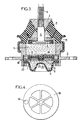
- Figure 1 of these drawings shows in axial section an anti-vibration support established according to the invention.
- FIG. 2 is a partial cross section of the same support according to arrows II-II, FIG. 1.
- Figure 3 shows in axial section another antivibration support established according to the invention.
- Figure 4 shows in plan one of the two grids of this support.
- each of the supports considered is intended to be interposed vertically or in a direction slightly inclined to the vertical between a rigid support member constituted by a vehicle chassis and a rigid supported member constituted by the internal combustion engine of this vehicle.
- a standby stud 4 whose threaded rod extends upwards is integral with the core 1 and is used for fixing the vehicle engine to this core.
- bowl 2 its edge is also connected to means (not shown) allowing its attachment to the chassis of the vehicle.
- the core 1, or more precisely the stud 4 is extended towards the inside of the housing by a foot 5 itself terminated by an enlarged shoe or piston 6.
- This piston 6 is dimensioned in such a way that an annular gap constituting a constricted passage p for the liquid is created between its periphery and the internal face opposite the housing 1, 2, 3.
- the bowl 2 is hollowed out by at least one orifice 7, single or multiple, the axial length of which is much less than the average diameter (here the average diameter is called the diameter of the circle having the same section than the port concerned).
- the hole in question is here associated with a rotary valve 8 for adjusting the degree of its opening.
- said valve 8 is angularly linked to the shaft 9 of a small electric motor 10 and it is arranged so as to be able to slide contiguously against the underside of the edge of each opening 7.
- any orifice 7 and the valve 8 can be given any desirable shape: in the embodiment illustrated by way of example, each orifice 7 has the shape of a circular sector extending over an arc of 60 degrees, and the valve has three identical flat sides also having the shape of circular sectors of 60 degrees.
- a waterproof and flexible bellows or membrane 11 is attached to the underside of the bowl 2 so as to form therewith a sealed pocket R with variable volume.
- a protective cover 12 envelops the bellows 11 and allows the tight assembly thereof on the edge of the bowl 2 by folding down its own edge circular, like a crimp, around the edges of the following axially juxtaposed parts: the bowl 2, bellows 11 and an annular reinforcement 13 embedded in the wall 3.
- each biasing of the piston 6 downwards no longer necessarily results in a relative rise, through the passage P, of a volume of liquid L equivalent to that expelled by this piston , by means of a corresponding deformation of the wall 3.
- the value of the frequency for which the annular column of liquid which surrounds the piston 6 enters into resonance is no longer equal to F0, but to a new value F1.
- this new value varies according to the degree of opening of the orifices 7 and increases in the same direction as this opening.
- control of the small electric motor 10 is advantageously slaved to the instantaneous frequency of the oscillations to be damped, and in particular to the frequency of the vibrations of the vehicle engine or, which amounts to the same thing, to the speed of rotation of the output shaft of this engine.
- this channel 14 plays a role substantially similar to that of the constricted passage P in that the column of liquid L disposed in said channel is also driven back into it alternately during the application of relative axial oscillations between the two elements 1 and 2, which ensures effective damping for a frequency which depends on the dimensions of channel 14, at least as long as that the orifices 7 remain closed or not very clear, the total disengagement of these orifices may have the effect of short-circuiting the channel 14.
- This embodiment essentially differs from the previous one in that the section of the light 7 is no longer adjustable at will: it is assumed here that it has its optimum value previously determined in the factory as a function of the intended application, for example using an adjustable opening prototype as described above.
- the valve 15 is contained with clearance between two plane and parallel grids 18 and 19 and it is constituted by a deformable rubber pad centered with a central button 20 with an enlarged head molded therewith and forced into a complementary central housing 21 of one of the grids.
- valve and rigid parts constituting the grids are such that, when the valve is not applied against one of the grids, the liquid L can circulate freely through them, at least as long as is not not reached a given value of the frequency - relatively "high” - of the vibrations to be damped, value corresponding to the "resonance" of the liquid mass then "strangled" in the nozzle formed by said grids.
- the lumen 7 is here the circular hole hollowed out in a washer 22 juxtaposed axially below the lower grid 19 and its mean diameter is preferably greater than that of the openings in each grid.
- the length, counted according to the direction of circulation of the liquid, of each lumen 7, is much smaller than the overall average diameter of this lumen.
- the ratio between said average diameter and said length is advantageously of the order of 5 to 20, or even greater than 20.
- the length of the light 7 is for example of the order of 2 to 3 mm for an average diameter of the order of 10 to 50 mm.
- the ratio between the mean diameter and the length is much less than 1 instead of being significantly more than 1, this ratio generally being less than 1/5 and even at 1/10.
- This support has a certain number of advantages compared to those previously known and in particular that of making possible in an extremely simple and effective manner an adjustment of the optimum damping frequency which corresponds to the resonance of the annular column. of liquid surrounding the piston which is immersed in the housing.
Landscapes
- Engineering & Computer Science (AREA)
- General Engineering & Computer Science (AREA)
- Mechanical Engineering (AREA)
- Combined Devices Of Dampers And Springs (AREA)
Applications Claiming Priority (2)
| Application Number | Priority Date | Filing Date | Title |
|---|---|---|---|
| FR909007088A FR2663101B1 (fr) | 1990-06-07 | 1990-06-07 | Perfectionnements apportes aux supports antivibratoires hydrauliques. |
| FR9007088 | 1990-06-07 |
Publications (3)
| Publication Number | Publication Date |
|---|---|
| EP0461024A2 true EP0461024A2 (de) | 1991-12-11 |
| EP0461024A3 EP0461024A3 (en) | 1992-10-21 |
| EP0461024B1 EP0461024B1 (de) | 1994-12-28 |
Family
ID=9397370
Family Applications (1)
| Application Number | Title | Priority Date | Filing Date |
|---|---|---|---|
| EP91401456A Revoked EP0461024B1 (de) | 1990-06-07 | 1991-06-04 | Hydraulische Antischwingungslager |
Country Status (6)
| Country | Link |
|---|---|
| US (1) | US5209460A (de) |
| EP (1) | EP0461024B1 (de) |
| JP (1) | JPH04231746A (de) |
| DE (1) | DE69106228T2 (de) |
| ES (1) | ES2066382T3 (de) |
| FR (1) | FR2663101B1 (de) |
Cited By (4)
| Publication number | Priority date | Publication date | Assignee | Title |
|---|---|---|---|---|
| GB2278660A (en) * | 1993-05-26 | 1994-12-07 | Honda Motor Co Ltd | Liquid-elastomer vibration-isolating device |
| WO1999027277A1 (de) * | 1997-11-21 | 1999-06-03 | Btr Avs Technical Centre Gmbh | Hydraulisch dämpfendes zweikammer-motorlager |
| DE19932584A1 (de) * | 1999-05-27 | 2000-12-21 | Freudenberg Carl Fa | Hydraulisch dämpfendes Lager |
| FR2831630A1 (fr) * | 2001-10-29 | 2003-05-02 | Hutchinson | Support antivibratoire hydraulique comportant un clapet de decouplage clipse |
Families Citing this family (14)
| Publication number | Priority date | Publication date | Assignee | Title |
|---|---|---|---|---|
| JP2585595Y2 (ja) * | 1993-02-22 | 1998-11-18 | 株式会社小松製作所 | ブルドーザのオペレータキャビンの支持装置 |
| JP3166493B2 (ja) * | 1994-06-28 | 2001-05-14 | 豊田合成株式会社 | 液封入防振装置 |
| US5540549A (en) * | 1994-08-05 | 1996-07-30 | Lord Corporation | Fluid damping devices |
| FR2765292B1 (fr) * | 1997-06-26 | 1999-09-17 | Peugeot | Systeme de commande d'un support hydroelastique |
| DE19902494C2 (de) * | 1999-01-22 | 2002-10-31 | Freudenberg Carl Kg | Umschaltbares Zweikammerstützlager mit hydraulischer Dämpfung |
| JP3489500B2 (ja) * | 1999-08-10 | 2004-01-19 | 東海ゴム工業株式会社 | 防振装置 |
| DE10057466A1 (de) * | 2000-11-20 | 2002-06-06 | Trelleborg Automotive Tech Ct | Hydraulisch dämpfendes Lager |
| DE10104458A1 (de) * | 2001-02-01 | 2002-09-19 | Zf Boge Gmbh | Hydraulisch dämpfendes Motorlager |
| FR2822911B1 (fr) * | 2001-04-02 | 2003-10-24 | Hutchinson | Support antivibratoire hydraulique |
| JP3849534B2 (ja) | 2002-01-29 | 2006-11-22 | 東海ゴム工業株式会社 | 流体封入式防振装置 |
| JP5641525B2 (ja) * | 2011-03-25 | 2014-12-17 | 住友理工株式会社 | 流体封入式能動型防振装置 |
| JP6063249B2 (ja) * | 2012-12-26 | 2017-01-18 | 東洋ゴム工業株式会社 | 防振装置 |
| DE102014211953A1 (de) | 2014-06-23 | 2015-12-24 | Contitech Vibration Control Gmbh | Hydrolager sowie Kraftfahrzeug mit einem derartigen Hydrolager |
| KR101845421B1 (ko) * | 2016-04-06 | 2018-05-18 | 현대자동차주식회사 | 엔진마운트 |
Family Cites Families (13)
| Publication number | Priority date | Publication date | Assignee | Title |
|---|---|---|---|---|
| DE3347274C2 (de) * | 1983-12-28 | 1987-02-26 | Lemförder Metallwaren AG, 2844 Lemförde | Hydraulischer Schwingungsdämpfer für elastische Stützlager in Kraftfahrzeugen |
| JPS61121281A (ja) * | 1984-11-16 | 1986-06-09 | 三洋電機株式会社 | 誘導加熱調理器の出力設定装置 |
| JPS61193006A (ja) * | 1985-02-22 | 1986-08-27 | Hitachi Ltd | 紙葉重複送り検出回路 |
| US4765601A (en) * | 1985-02-28 | 1988-08-23 | General Motors Corporation | Hydraulic-elastomeric mount |
| JPS62180130A (ja) * | 1986-02-03 | 1987-08-07 | Honda Motor Co Ltd | 可変オリフイスを有する複合エンジンマウント |
| JPS62215141A (ja) * | 1986-03-14 | 1987-09-21 | Bridgestone Corp | 防振装置 |
| JPH0826917B2 (ja) * | 1986-05-16 | 1996-03-21 | 本田技研工業株式会社 | 自動車のエンジン支持装置 |
| DE3619687A1 (de) * | 1986-06-11 | 1987-12-17 | Freudenberg Carl Fa | Zweikammermotorlager |
| FR2610054B1 (fr) * | 1987-01-26 | 1991-08-16 | Hutchinson | Perfectionnements apportes aux supports antivibratoires hydrauliques |
| DE3705579C2 (de) * | 1987-02-21 | 1995-11-02 | Bosch Gmbh Robert | Verstellbares Motorlager |
| DE3721811A1 (de) * | 1987-07-02 | 1989-01-12 | Freudenberg Carl Fa | Motorlager |
| IT1211187B (it) * | 1987-07-07 | 1989-10-12 | Ages Spa | Supporto ammortizzante per la sospensione di un corpo oscillante ad una struttura di sopporto partico larmente per la sospensione del motore al telaio in un autoveicolo |
| US4796874A (en) * | 1987-10-02 | 1989-01-10 | General Motors Corporation | Electronic hydraulic mount with continuously variable control |
-
1990
- 1990-06-07 FR FR909007088A patent/FR2663101B1/fr not_active Expired - Fee Related
-
1991
- 1991-06-04 ES ES91401456T patent/ES2066382T3/es not_active Expired - Lifetime
- 1991-06-04 EP EP91401456A patent/EP0461024B1/de not_active Revoked
- 1991-06-04 DE DE69106228T patent/DE69106228T2/de not_active Revoked
- 1991-06-07 JP JP3136831A patent/JPH04231746A/ja active Pending
- 1991-06-07 US US07/710,430 patent/US5209460A/en not_active Expired - Fee Related
Cited By (8)
| Publication number | Priority date | Publication date | Assignee | Title |
|---|---|---|---|---|
| GB2278660A (en) * | 1993-05-26 | 1994-12-07 | Honda Motor Co Ltd | Liquid-elastomer vibration-isolating device |
| US5443574A (en) * | 1993-05-26 | 1995-08-22 | Honda Giken Kogyo Kabushiki Kaisha | Liquid-sealing type vibration-isolating device |
| GB2278660B (en) * | 1993-05-26 | 1996-11-27 | Honda Motor Co Ltd | Liquid-sealing type vibration-isolating device |
| WO1999027277A1 (de) * | 1997-11-21 | 1999-06-03 | Btr Avs Technical Centre Gmbh | Hydraulisch dämpfendes zweikammer-motorlager |
| DE19932584A1 (de) * | 1999-05-27 | 2000-12-21 | Freudenberg Carl Fa | Hydraulisch dämpfendes Lager |
| FR2831630A1 (fr) * | 2001-10-29 | 2003-05-02 | Hutchinson | Support antivibratoire hydraulique comportant un clapet de decouplage clipse |
| EP1306576A1 (de) * | 2001-10-29 | 2003-05-02 | Hutchinson | Hydraulisches, schwingungsdämpfendes Lager mit einem verrasteten Entkopplungsventil |
| US6676117B2 (en) | 2001-10-29 | 2004-01-13 | Hutchinson | Hydraulic vibration-damping support including a clip-on decoupling flap |
Also Published As
| Publication number | Publication date |
|---|---|
| DE69106228D1 (de) | 1995-02-09 |
| ES2066382T3 (es) | 1995-03-01 |
| EP0461024B1 (de) | 1994-12-28 |
| EP0461024A3 (en) | 1992-10-21 |
| FR2663101A1 (fr) | 1991-12-13 |
| DE69106228T2 (de) | 1995-08-10 |
| FR2663101B1 (fr) | 1994-08-05 |
| US5209460A (en) | 1993-05-11 |
| JPH04231746A (ja) | 1992-08-20 |
Similar Documents
| Publication | Publication Date | Title |
|---|---|---|
| EP0461024B1 (de) | Hydraulische Antischwingungslager | |
| FR2593869A1 (fr) | Suspension composite a ouverture variable pour moteur | |
| EP0248714B1 (de) | Hülsen für hydraulische Antischwingungslager | |
| EP0840035B1 (de) | Hydraulisches, schwingungsdämpfendes Lager | |
| EP2180207B1 (de) | Schwingungstilger und Fahrzeug mit einem solchen Schwingungstilger | |
| EP0223712B1 (de) | Änderungen an hydraulischen Dämpfern | |
| FR2600138A1 (fr) | Appareil antivibration utilisant un fluide | |
| FR2688844A1 (fr) | Perfectionnements aux dispositifs antivibratoires hydrauliques. | |
| EP0278824B1 (de) | Hydraulische Antischwingungslager | |
| EP0306369B1 (de) | Hydraulisch gedämpfte Lagerbuchsen | |
| EP0191703A1 (de) | Änderungen an hydraulischen Antischwingungslagern | |
| FR2812362A1 (fr) | Support antivibratoire hydraulique et son procede de fabrication | |
| FR2617932A1 (fr) | Support amortisseur pour la suspension d'un corps oscillant sur une structure support, en particulier pour la suspension du moteur sur le chassis d'un vehicule automobile | |
| FR2650355A1 (fr) | Perfectionnements aux dispositifs amortisseurs de vibrations | |
| FR2627564A1 (fr) | Support caoutchouc a amortissement hydraulique | |
| EP0297974B1 (de) | Hydraulisch gedämpfte Lager | |
| EP0225227B1 (de) | Änderungen an hydraulischen Anti-Schwingungslagern | |
| FR2675222A1 (fr) | Support elastique rempli par un fluide, comportant un amortisseur dynamique pour une console de montage et utilisant un capot a diaphragme d'equilibre. | |
| EP0241353B1 (de) | Änderungen an Antischwingungslagern vom hydraulischen Typ | |
| EP0305246A1 (de) | Hydraulisch gedämpfte Lager | |
| FR2628805A1 (fr) | Structure de montage elastique a remplissage de fluide a elements mobiles et a orifices | |
| FR3103527A1 (fr) | Elément de séparation de module hydraulique antivibratoire et module hydraulique antivibratoire équipé d’un tel élément de séparation | |
| EP0849494B1 (de) | Hydroelastisches Lager, insbesondere zum Lagern einer Antriebseinheit in einem Kfz | |
| FR2671839A1 (fr) | Perfectionnements aux supports antivibratoires hydrauliques. | |
| FR2841621A1 (fr) | "dispositif d'articulation hydroelastique a effet axial" |
Legal Events
| Date | Code | Title | Description |
|---|---|---|---|
| PUAI | Public reference made under article 153(3) epc to a published international application that has entered the european phase |
Free format text: ORIGINAL CODE: 0009012 |
|
| AK | Designated contracting states |
Kind code of ref document: A2 Designated state(s): DE ES FR GB IT SE |
|
| PUAL | Search report despatched |
Free format text: ORIGINAL CODE: 0009013 |
|
| AK | Designated contracting states |
Kind code of ref document: A3 Designated state(s): DE ES FR GB IT SE |
|
| 17P | Request for examination filed |
Effective date: 19921109 |
|
| 17Q | First examination report despatched |
Effective date: 19931123 |
|
| GRAA | (expected) grant |
Free format text: ORIGINAL CODE: 0009210 |
|
| AK | Designated contracting states |
Kind code of ref document: B1 Designated state(s): DE ES FR GB IT SE |
|
| REF | Corresponds to: |
Ref document number: 69106228 Country of ref document: DE Date of ref document: 19950209 |
|
| GBT | Gb: translation of ep patent filed (gb section 77(6)(a)/1977) |
Effective date: 19950118 |
|
| REG | Reference to a national code |
Ref country code: ES Ref legal event code: FG2A Ref document number: 2066382 Country of ref document: ES Kind code of ref document: T3 |
|
| ITF | It: translation for a ep patent filed | ||
| PGFP | Annual fee paid to national office [announced via postgrant information from national office to epo] |
Ref country code: FR Payment date: 19950529 Year of fee payment: 5 |
|
| PGFP | Annual fee paid to national office [announced via postgrant information from national office to epo] |
Ref country code: GB Payment date: 19950530 Year of fee payment: 5 |
|
| PGFP | Annual fee paid to national office [announced via postgrant information from national office to epo] |
Ref country code: ES Payment date: 19950609 Year of fee payment: 5 |
|
| PGFP | Annual fee paid to national office [announced via postgrant information from national office to epo] |
Ref country code: SE Payment date: 19950621 Year of fee payment: 5 |
|
| PGFP | Annual fee paid to national office [announced via postgrant information from national office to epo] |
Ref country code: DE Payment date: 19950623 Year of fee payment: 5 |
|
| PLBI | Opposition filed |
Free format text: ORIGINAL CODE: 0009260 |
|
| 26 | Opposition filed |
Opponent name: CONTINENTAL AG Effective date: 19950921 |
|
| PLBF | Reply of patent proprietor to notice(s) of opposition |
Free format text: ORIGINAL CODE: EPIDOS OBSO |
|
| PLBF | Reply of patent proprietor to notice(s) of opposition |
Free format text: ORIGINAL CODE: EPIDOS OBSO |
|
| PLBF | Reply of patent proprietor to notice(s) of opposition |
Free format text: ORIGINAL CODE: EPIDOS OBSO |
|
| RDAH | Patent revoked |
Free format text: ORIGINAL CODE: EPIDOS REVO |
|
| RDAG | Patent revoked |
Free format text: ORIGINAL CODE: 0009271 |
|
| STAA | Information on the status of an ep patent application or granted ep patent |
Free format text: STATUS: PATENT REVOKED |
|
| GBPR | Gb: patent revoked under art. 102 of the ep convention designating the uk as contracting state |
Free format text: 960727 |
|
| 27W | Patent revoked |
Effective date: 19960727 |