EP0461061A2 - Tragvorrichtung für Münzprüfer - Google Patents
Tragvorrichtung für Münzprüfer Download PDFInfo
- Publication number
- EP0461061A2 EP0461061A2 EP91500054A EP91500054A EP0461061A2 EP 0461061 A2 EP0461061 A2 EP 0461061A2 EP 91500054 A EP91500054 A EP 91500054A EP 91500054 A EP91500054 A EP 91500054A EP 0461061 A2 EP0461061 A2 EP 0461061A2
- Authority
- EP
- European Patent Office
- Prior art keywords
- frame
- coins
- passage
- holder
- tokens
- Prior art date
- Legal status (The legal status is an assumption and is not a legal conclusion. Google has not performed a legal analysis and makes no representation as to the accuracy of the status listed.)
- Granted
Links
Images

Classifications
-
- G—PHYSICS
- G07—CHECKING-DEVICES
- G07D—HANDLING OF COINS OR VALUABLE PAPERS, e.g. TESTING, SORTING BY DENOMINATIONS, COUNTING, DISPENSING, CHANGING OR DEPOSITING
- G07D5/00—Testing specially adapted to determine the identity or genuineness of coins, e.g. for segregating coins which are unacceptable or alien to a currency
Definitions
- This invention relates to a frame-holder for removably housing validation devices in coin-operated dispensing machines, amusement or gaming machines and automatic apparatus to cancel payment.
- the body frame or supporting members must incorporate in addition, integral therewith, a shaft to mount in rotating articulation an elastically loaded lever to feed back the defective coins, the lever being interrelated with a push button for such purpose and protruding from a front panel, on whose back is fixed the frame-holder, and which operates on a hinged element that diverts the jammed coins or tokens toward a rejecting path.
- Spanish utility model n° 268.966 and Spanish patent n° 87 00623 relate to the above type of device.
- the invention proposes essentially to construct the assembly with only a single body obtained by an injection molding operation and therefore of a material that can be used through said process, advantageously of plastic material, in which are integrated not only the means forming its own support, but also the path for the entering of the coins, exit path and reject or feeding back path, a supporting shaft to install a lever that must operates a feeding back device to release jammed coins or tokens, and a support for detecting means and illumination of a push-button to operate the lever.
- This single body has conformed a first inclined path or channel of rectangular cross section for receiving the inserted coins or tokens, that ends in a slotted path which remains level to one of the side walls of a large prismatic rectangular recess of a width and depth big enough to house the body of any kind of coins validation device (mechanical, electromechanical, etc.) the recess having in the wall close to the slotted path, from this opening and until the opposite side, a large aperture through which extends parallel to the recess back side an appendage from which perpendicularly protrudes a cylindrical stem or shaft.
- the recess has an opening to ease the mounting of the lever to feed back the jammed coins or tokens.
- the stem has a first thicker part, to support a spring forming a loop and extended in two divergent arms, one of the arms being supported on one of the recess side walls and the second arm latching to one part of the lever.
- the recess side edges have close to the smaller sides thereof grooves and notches opposite to each other for positioning and retaining by an elastic element the validation device body inside the prismatic recess.
- the grooves of rectangular profile and notches of L-shaped profile are introduced shafts or pins on the sides of the validation device and one of them forces an elastic element whose end, having an elbowed shaped profile, remains arranged inside one of the rectangular grooves, until the shaft passes a ramp thereon and enters the groove remaining trapped by the elastic element on the side wall.
- the single body holder On one of the sides of the slot for insertion of the coins and flanking the feeding back box opening the single body holder has flanges provided with mounting holes to mount the frame-holder to an assembling panel.
- Another characteristic of the invention is the fact that the coins or tokens entrance path has aligned cross holes. These holes though used during the manufacturing process of the path for immobilizing and perfect centering of a slide required in the mold have in addition the function to make possible in a simple way the withdrawal of coins, tokens or other objects that become trapped in the path.
- one of the walls forming the coin entrance oblique path is continued above the path and has a protrusion of triangular profile with an offset on one of the wall sides to mount an illumination bushing provided with an anchoring clip.
- the single body frame-holder will be advantageously obtained as stated by means of an injection molding operation with the assistance of three slides to form the three paths, two of them parallel and the third one oblique and longer and centered during the process by positioning means that will later on give rise to the mentioned centered holes.
- the coins acceptance path also has an arch-shaped cross passageway to facilitate arranging across it a rod interrelated with a microswitch to record the number of coins or tokens accepted.
- the recess side wall extends beyond the slot preventing access to the rod from the feeding back box, whose wider slot remains virtually level with the recess edge.
- the coin acceptance path has furthermore, close to one of its sides, upright grooves, facing each other, for guided insertion and setting of supplementary elements, designed to throttle the coin passageway to adapt it to the physical characteristics of the coins or tokens under test in the validation device.
- supplementary elements designed to throttle the coin passageway to adapt it to the physical characteristics of the coins or tokens under test in the validation device.
- a set of supplementary elements of different dimensions are selectively insertable within the coins acceptance path.
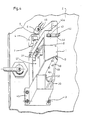
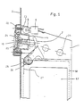
- the frame-holder of the invention is formed by a single body -1- having a large prismatic rectangular recess -40- to house the body of a coin or tokens validation device, not shown, having in one side a first inclined passage or channel -29-, provided with side transversal holes -34-, for inserting coins or tokens, a second passage or channel -30- for receiving valid coins and directing them toward a collection thank and third passage -31- that communicates with a box -32- which is outwardly open or with a vertical passage -32a- (Fig. 1a).
- the dotted lines and arrows in this figure is shown the path along which the coins or tokens run through the validation device and the body -1- depending on whetter they are accepted or not.
- the front edges of the sides forming recess (40) sides have chamfers -41- defining a mouth or entrance that provides easy entry of the validation device body and notches -13- and -14- for positioning and locking of the validation device which is provided on its sides with side shafts that will remain housed inside the notches and grooves -13- and -14-, and retained by a metallic plate -42- fastened with a screw -43- to the external wall of the side of recess -40- and provided with a protuberance -43a- (see Fig. 4) that remains inserted in a hole at the side of the recess -40-.
- the elbowed end of plate -42- is provided with an opening -44- overlapping the entrance of one of the mentioned grooves -14-.
- the single-part body -1- has flanges -45- and -46- with holes -47- -48- therein to fasten a panel -2- thereto by screws or bolts inserted through holes -47- and -48- and retained by locknuts -3-.
- the single body has further a stem or shaft -26- for mounting a lever -7- to operate the feeding back device of the validation device, the lever being known per se.
- Fig. 1 it can be seen that the path -30- for accepting coins has close to one of its sides upright grooves -49- facing each other and an offset -50- .
- Grooves -49- are for guiding an elongated supplemental element -51-, of T-shaped cross section.
- Elongated rib or stem -54- thereon has a width significantly equivalent to that of passageway -30- and side branches or flanges -52-, forming the head of the T have a width, that slidingly fit in grooves -49- .
- a beading -53- is provided for engaging in offset -50- when supplemental element -51- is fully inserted.
- FIGs. 2 and 3 are shown two supplemental elements -51- with different heights -a- and -b- of their elongated ribs -54-
- Fig. 1 can also be seen the deep offset -56- of curved sides, together to one of the larger sides of passage -33- designed to allow the passage of a lever to block the withdrawal of the coin once it is introduced, such lever being known per se and incorporated in most of the prior art validation devices.
- Fig. 4 and 5 there appears the illumination element comprised of a bushing -6- and bulb -5- that is locked to the frame-holder -1- by means of an elastic jaw -46- that encloses a protrusion -60- provided with an offset -28-.
- Lever -7- operates a means to feed back the coins jammed into the validation device.
- Lever -7- is spring loaded by spring -27- and is retained by screw -25-.
- the frame-holder -1- is associated with panel -2- and a push button -19-, spring loaded by spring -20- is mounted therein with its stem -24- facing the lever -7-.
- the push button is mounted in a frame -4- fastened to a second frame -22- which is locked by screws -23- to the panel -2- .
- the recess bottom is formed by the large opening -57- level with the recess bottom and delimited at its other three sides by a narrow frame -58-.
- Fig. 4 are shown some hollow protuberances -59- in the back part of the plate -55- designed for mounting the microswitch on plate -55- by lock screws.
Landscapes
- Physics & Mathematics (AREA)
- General Physics & Mathematics (AREA)
- Control Of Vending Devices And Auxiliary Devices For Vending Devices (AREA)
- Acyclic And Carbocyclic Compounds In Medicinal Compositions (AREA)
- Medicines That Contain Protein Lipid Enzymes And Other Medicines (AREA)
- Coin-Freed Apparatuses For Hiring Articles (AREA)
- Injection Moulding Of Plastics Or The Like (AREA)
Applications Claiming Priority (4)
| Application Number | Priority Date | Filing Date | Title |
|---|---|---|---|
| ES9001540 | 1990-06-05 | ||
| ES9001540A ES2024829A6 (es) | 1990-06-05 | 1990-06-05 | Carcasa-soporte para dispositivos selectores de monedas o fichas. |
| ES9100327 | 1991-02-07 | ||
| ES9100327A ES2030363A6 (es) | 1991-02-07 | 1991-02-07 | Perfeccionamientos en el objeto de la patente principal n{ 90 01540 por "carcasa-soporte para dispositivos selectores de monedas o fichas". |
Publications (3)
| Publication Number | Publication Date |
|---|---|
| EP0461061A2 true EP0461061A2 (de) | 1991-12-11 |
| EP0461061A3 EP0461061A3 (en) | 1992-12-23 |
| EP0461061B1 EP0461061B1 (de) | 1995-06-14 |
Family
ID=26154476
Family Applications (1)
| Application Number | Title | Priority Date | Filing Date |
|---|---|---|---|
| EP91500054A Expired - Lifetime EP0461061B1 (de) | 1990-06-05 | 1991-06-05 | Tragvorrichtung für Münzprüfer |
Country Status (4)
| Country | Link |
|---|---|
| US (1) | US5165511A (de) |
| EP (1) | EP0461061B1 (de) |
| AT (1) | ATE123889T1 (de) |
| DE (1) | DE69110354T2 (de) |
Cited By (1)
| Publication number | Priority date | Publication date | Assignee | Title |
|---|---|---|---|---|
| EP0511150A3 (de) * | 1991-04-22 | 1992-12-30 | Industrias Lorenzo, S.A. | Tragvorrichtung für Münzprüfer samt Sortiervorrichtung |
Families Citing this family (5)
| Publication number | Priority date | Publication date | Assignee | Title |
|---|---|---|---|---|
| JP2540528Y2 (ja) * | 1991-12-09 | 1997-07-09 | 旭精工株式会社 | コインドア |
| JPH07244763A (ja) * | 1994-03-03 | 1995-09-19 | Ace Denken:Kk | コインセパレータの取付け構造 |
| US5967287A (en) * | 1998-01-15 | 1999-10-19 | Cole; Joseph | Internally mounted, externally lockable and removable coin comparator mounting device for video vending machines and the like |
| US7635059B1 (en) | 2000-02-02 | 2009-12-22 | Imonex Services, Inc. | Apparatus and method for rejecting jammed coins |
| TWM247958U (en) * | 2003-10-27 | 2004-10-21 | Int Currency Tech | Improved coin-separation device of coin receiver |
Family Cites Families (14)
| Publication number | Priority date | Publication date | Assignee | Title |
|---|---|---|---|---|
| US2237132A (en) * | 1939-12-28 | 1941-04-01 | Wurlitzer Co | Photoelectric coin registering device |
| US2539855A (en) * | 1945-08-20 | 1951-01-30 | Raymond T Moloney | Coin chute |
| US3156340A (en) * | 1961-05-03 | 1964-11-10 | Jack H Arkes | Coin operated vending machine |
| US3907088A (en) * | 1974-05-06 | 1975-09-23 | Nordon Ind Inc | Apparatus for sensing the passage of coins through and the retention of coins in a coin handling mechanism |
| GB2040526B (en) * | 1978-08-02 | 1982-07-28 | Coburn O W | Magnetic coin element sensor |
| US4515262A (en) * | 1983-03-28 | 1985-05-07 | Equipment Systems & Devices, Inc. | Coin slide |
| US4583630A (en) * | 1984-09-25 | 1986-04-22 | Bernard Kalishman | Coin chutes for a coin apparatus |
| US4651862A (en) * | 1985-06-10 | 1987-03-24 | Greenfield Jr Irving E | Dual temperature beverage dispenser with removable operating module |
| ES8708074A1 (es) * | 1986-05-21 | 1987-09-01 | Azkoyen Ind Sa | Perfeccionamientos en mecanismos selectores de moneda |
| FR2611949B3 (fr) * | 1987-03-06 | 1989-06-09 | Azkoyen Ind Sa | Trieuse de pieces de monnaie pour machines fonctionnant a l'aide de pieces de monnaie |
| US4911280A (en) * | 1987-04-27 | 1990-03-27 | Bruner Philemon L | Method and apparatus for deflecting coins while maintaining an on-edge orientation |
| DE3727927C2 (de) * | 1987-08-21 | 1996-07-25 | Paul Gauselmann | Münzeinheit für ein Unterhaltungsgerät |
| CH670167A5 (de) * | 1987-12-31 | 1989-05-12 | Automaten Ag | |
| US5048663A (en) * | 1988-09-17 | 1991-09-17 | Asahi Seiko Kabushiki Kaisha | Electronic coin acceptor |
-
1991
- 1991-06-05 DE DE69110354T patent/DE69110354T2/de not_active Expired - Fee Related
- 1991-06-05 AT AT91500054T patent/ATE123889T1/de not_active IP Right Cessation
- 1991-06-05 EP EP91500054A patent/EP0461061B1/de not_active Expired - Lifetime
- 1991-06-05 US US07/710,021 patent/US5165511A/en not_active Expired - Lifetime
Cited By (1)
| Publication number | Priority date | Publication date | Assignee | Title |
|---|---|---|---|---|
| EP0511150A3 (de) * | 1991-04-22 | 1992-12-30 | Industrias Lorenzo, S.A. | Tragvorrichtung für Münzprüfer samt Sortiervorrichtung |
Also Published As
| Publication number | Publication date |
|---|---|
| DE69110354D1 (de) | 1995-07-20 |
| DE69110354T2 (de) | 1996-01-25 |
| US5165511A (en) | 1992-11-24 |
| EP0461061A3 (en) | 1992-12-23 |
| ATE123889T1 (de) | 1995-06-15 |
| EP0461061B1 (de) | 1995-06-14 |
Similar Documents
| Publication | Publication Date | Title |
|---|---|---|
| US6086473A (en) | Coin processing device with improved coin storage system | |
| US4509631A (en) | Coin door assembly | |
| EP0461061B1 (de) | Tragvorrichtung für Münzprüfer | |
| JP3038058B2 (ja) | パチンコ機 | |
| US5048663A (en) | Electronic coin acceptor | |
| US5082099A (en) | Apparatus for accepting two kinds of coins | |
| JP3027636B2 (ja) | パチンコ機 | |
| JPH0552984U (ja) | コインドア | |
| JP3059548B2 (ja) | パチンコ機 | |
| JP3024831B2 (ja) | パチンコ機 | |
| JPH0542859Y2 (de) | ||
| JP2000093585A (ja) | 弾球遊技機の球戻り防止装置 | |
| JPH05174222A (ja) | コインメカニズム | |
| JP3118077B2 (ja) | パチンコ機の球排出装置 | |
| JP3040861B2 (ja) | パチンコ機 | |
| JP3014187B2 (ja) | パチンコ機 | |
| JP3014820B2 (ja) | パチンコ機の球貯留タンク | |
| JP2978713B2 (ja) | パチンコ機の入賞装置 | |
| CA2110566A1 (en) | Deposit lock and token for a transport cart | |
| US5076415A (en) | Coin operated device | |
| US3946849A (en) | Coin-chute for testing the ferrous content, weight, and presence of an aperture in coins | |
| JPH087491Y2 (ja) | コイン貸出機 | |
| EP0511150A2 (de) | Tragvorrichtung für Münzprüfer samt Sortiervorrichtung | |
| KR910007607Y1 (ko) | 자판기의 동전 반환 장치 | |
| JP2549083B2 (ja) | 弾球遊技機の入賞球回収装置 |
Legal Events
| Date | Code | Title | Description |
|---|---|---|---|
| PUAI | Public reference made under article 153(3) epc to a published international application that has entered the european phase |
Free format text: ORIGINAL CODE: 0009012 |
|
| AK | Designated contracting states |
Kind code of ref document: A2 Designated state(s): AT BE DE FR GB IT NL |
|
| PUAL | Search report despatched |
Free format text: ORIGINAL CODE: 0009013 |
|
| AK | Designated contracting states |
Kind code of ref document: A3 Designated state(s): AT BE DE FR GB IT NL |
|
| 17P | Request for examination filed |
Effective date: 19930514 |
|
| 17Q | First examination report despatched |
Effective date: 19940317 |
|
| GRAA | (expected) grant |
Free format text: ORIGINAL CODE: 0009210 |
|
| AK | Designated contracting states |
Kind code of ref document: B1 Designated state(s): AT BE DE FR GB IT NL |
|
| PG25 | Lapsed in a contracting state [announced via postgrant information from national office to epo] |
Ref country code: AT Effective date: 19950614 Ref country code: BE Effective date: 19950614 |
|
| REF | Corresponds to: |
Ref document number: 123889 Country of ref document: AT Date of ref document: 19950615 Kind code of ref document: T |
|
| REF | Corresponds to: |
Ref document number: 69110354 Country of ref document: DE Date of ref document: 19950720 |
|
| ITF | It: translation for a ep patent filed | ||
| ET | Fr: translation filed | ||
| PLBE | No opposition filed within time limit |
Free format text: ORIGINAL CODE: 0009261 |
|
| STAA | Information on the status of an ep patent application or granted ep patent |
Free format text: STATUS: NO OPPOSITION FILED WITHIN TIME LIMIT |
|
| 26N | No opposition filed | ||
| REG | Reference to a national code |
Ref country code: GB Ref legal event code: IF02 |
|
| PGFP | Annual fee paid to national office [announced via postgrant information from national office to epo] |
Ref country code: IT Payment date: 20080613 Year of fee payment: 18 |
|
| PGFP | Annual fee paid to national office [announced via postgrant information from national office to epo] |
Ref country code: FR Payment date: 20080620 Year of fee payment: 18 |
|
| PGFP | Annual fee paid to national office [announced via postgrant information from national office to epo] |
Ref country code: NL Payment date: 20090630 Year of fee payment: 19 |
|
| PGFP | Annual fee paid to national office [announced via postgrant information from national office to epo] |
Ref country code: DE Payment date: 20090826 Year of fee payment: 19 Ref country code: GB Payment date: 20090629 Year of fee payment: 19 |
|
| REG | Reference to a national code |
Ref country code: NL Ref legal event code: V1 Effective date: 20110101 |
|
| GBPC | Gb: european patent ceased through non-payment of renewal fee |
Effective date: 20100605 |
|
| REG | Reference to a national code |
Ref country code: FR Ref legal event code: ST Effective date: 20110228 |
|
| PG25 | Lapsed in a contracting state [announced via postgrant information from national office to epo] |
Ref country code: IT Free format text: LAPSE BECAUSE OF NON-PAYMENT OF DUE FEES Effective date: 20090605 |
|
| PG25 | Lapsed in a contracting state [announced via postgrant information from national office to epo] |
Ref country code: DE Free format text: LAPSE BECAUSE OF NON-PAYMENT OF DUE FEES Effective date: 20110101 |
|
| PG25 | Lapsed in a contracting state [announced via postgrant information from national office to epo] |
Ref country code: NL Free format text: LAPSE BECAUSE OF NON-PAYMENT OF DUE FEES Effective date: 20110101 Ref country code: FR Free format text: LAPSE BECAUSE OF NON-PAYMENT OF DUE FEES Effective date: 20100630 |
|
| PG25 | Lapsed in a contracting state [announced via postgrant information from national office to epo] |
Ref country code: GB Free format text: LAPSE BECAUSE OF NON-PAYMENT OF DUE FEES Effective date: 20100605 |