EP0461102A2 - Capteur sensible à la température - Google Patents
Capteur sensible à la température Download PDFInfo
- Publication number
- EP0461102A2 EP0461102A2 EP91890115A EP91890115A EP0461102A2 EP 0461102 A2 EP0461102 A2 EP 0461102A2 EP 91890115 A EP91890115 A EP 91890115A EP 91890115 A EP91890115 A EP 91890115A EP 0461102 A2 EP0461102 A2 EP 0461102A2
- Authority
- EP
- European Patent Office
- Prior art keywords
- wire
- resistance wire
- carrier film
- sensor
- windings
- Prior art date
- Legal status (The legal status is an assumption and is not a legal conclusion. Google has not performed a legal analysis and makes no representation as to the accuracy of the status listed.)
- Ceased
Links
Images


Classifications
-
- G—PHYSICS
- G01—MEASURING; TESTING
- G01K—MEASURING TEMPERATURE; MEASURING QUANTITY OF HEAT; THERMALLY-SENSITIVE ELEMENTS NOT OTHERWISE PROVIDED FOR
- G01K7/00—Measuring temperature based on the use of electric or magnetic elements directly sensitive to heat ; Power supply therefor, e.g. using thermoelectric elements
- G01K7/16—Measuring temperature based on the use of electric or magnetic elements directly sensitive to heat ; Power supply therefor, e.g. using thermoelectric elements using resistive elements
- G01K7/18—Measuring temperature based on the use of electric or magnetic elements directly sensitive to heat ; Power supply therefor, e.g. using thermoelectric elements using resistive elements the element being a linear resistance, e.g. platinum resistance thermometer
- G01K7/183—Measuring temperature based on the use of electric or magnetic elements directly sensitive to heat ; Power supply therefor, e.g. using thermoelectric elements using resistive elements the element being a linear resistance, e.g. platinum resistance thermometer characterised by the use of the resistive element
Definitions
- the invention relates to a sensor for detecting the temperature, the heat content and similar quantities, for example for water heaters, night or buffer storage, comprising a resistance wire and a connected voltage measurement system.
- Resistance-based sensors in which the temperature-dependent change in the electrical resistance is displayed by means of a corresponding measuring device, have been known for a long time for detecting the temperature, but also the heat content of a certain amount of a medium.
- the starting material for such sensors are industrially manufactured resistance wires. These are available in some specified alloys and in certain discrete cross-sectional gradations. The resistance, and thus the displayed value, depends on the wire length, the wire cross-section and the alloy used, which means that there are restrictions in many applications, e.g. with regard to the size of the sensor and the device, the value range of the resistor, etc. . On the other hand, however, manufacturing tolerances result in deviations of up to 10% from the theoretical resistance value. Both facts complicate the design of a sensor with high accuracy and resolution, i.e. a sensor in which small changes in temperature cause sufficiently large changes in resistance, e.g. for further processing in electronic circuits.
- DE-OS 2 261 531 describes a temperature resistance sensor in which the resistance wire extends straight near a longitudinal edge of the carrier material and is returned in meandering paths.
- DE-OS 2 048 489 also describes a temperature surface sensor in which the straight line Sections of the resistance wire, also meandering, are aligned parallel to the longitudinal direction of the sensor.
- flat, rigid base covers are provided, so that these sensors are only suitable for spot measurements on flat surfaces.
- the meandering application of the resistance wire requires a mechanically complex and time-consuming production.
- the object of the invention was therefore a sensor based on resistance with increased accuracy and resolution, which can be produced easily and quickly with little effort.
- the sensor should also be adapted to larger dimensions of the surface of the respective device.
- Another task was to be able to compensate for the manufacturing tolerances of the starting materials of the measuring sensor in a simple and quick manner during the course of production.
- the resistance wire is attached to a flexible carrier film in at least two, preferably several overlapping loops or windings.
- the loop arrangement makes it possible to accommodate more resistance wire over the same overall length of the sensor, while at the same time the effort for manufacture, both manually and mechanically, remains very low.
- the wire in the sensor according to the invention instead of placing the resistance wire in complicated meandering paths, the wire in the sensor according to the invention only has to be unwound in two opposite directions, while the corresponding path has to be traversed in the case of meandering resistance wires.
- the greater length of the resistance wire ensures the desired increase in the absolute resistance values as well as the difference in the resistance values for a given temperature difference. As a result, the prerequisites necessary for fine-level measurement value acquisition and further processing of the sensor signals are met.
- the flexible carrier film allows the sensor according to the invention to be adapted to any surface shape, even with relatively large dimensions of the sensor.
- the width of the sensor is small compared to its longitudinal dimension.
- This has the further advantage that the adaptation to the surface of the container essentially only has to be carried out in one dimension, namely the longitudinal dimension of the longitudinal sensor.
- the task of compensating for manufacturing tolerances of the resistance wires is achieved in that a trimming potentiometer is provided in the course of the resistance wire.
- the resistance wire is connected at one end to the ground connection of a temperature sensor, which is preferably also attached to the carrier film, and that a voltage divider circuit is provided at the other end of the resistance wire, with one contact of which, preferably with the interposition of a trim potentiometer, a supply voltage is applied and the other contact is connected to the voltage measurement system.
- the inventive method for producing the measuring sensor provides that, taking into account the cross-section and material of the resistance wire, the number of windings or loops required for obtaining the desired output signal and their length is determined and made by machine or by hand and the wire at least partially on a carrier film is applied, preferably glued, and then the manufacturing tolerances of the wire are compensated by adjusting the wire length regardless of the dimensions of the sensor itself.
- Advantageous variants of this method according to the invention consist in that, taking into account the cross section and material of the resistance wire, the number of windings or loops required to obtain the desired output signal and their length determined and made by machine or by hand and the wire is at least partially applied, preferably glued, onto a carrier foil, and then the manufacturing tolerances of the wire are compensated for by connecting and adjusting a trimming potentiometer or a voltage divider circuit, and the additional components are applied, preferably adhered, to the carrier foil.
- a particular simplification of the manufacture of the sensor according to the invention can be achieved in that the windings or loops of the resistance wire are placed around at least one, preferably two, temporary fastening elements which at most penetrate the carrier film.
- the fasteners are only present during the manufacture of the measuring sensor in this case and are removed again after the wire has been applied to the carrier film and the fastening thereon.
- These fastening elements are preferably spikes, poles or the like of the production machine into which the carrier film is inserted.
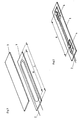
- Fig. 1 shows the basic structure of the sensor according to the invention
- Fig. 2 and 3 illustrate embodiments with fasteners
- Fig. 4 shows an advantageous variant of the sensor with correction option
- Fig. 5 shows a sensor with compensating voltage divider circuit.
- Fig. 1 denotes a flexible carrier film, which is preferably designed as a double-sided adhesive tape.
- the resistance wire 2 is attached to the said carrier film 1 in at least two windings or loops. As shown in the figures, the individual windings overlap each other.
- a plurality of windings or loops are preferably provided in order to obtain the change in resistance per temperature interval required for fine-level measurement value acquisition.
- a protective film 3 is also advantageously provided, which covers the resistance wire 2 or all components attached to the carrier film 1 and thus mechanically protects them.
- the protective or cover film 3 is preferably glued to the carrier film 1.
- the required number of loops of the wire 2 and their length A are initially determined.
- the loops or windings are then made manually or by machine. This essentially comprises guiding the resistance wire 2 in two opposite directions. It is easy to see that these movements, both manually and mechanically, are much easier to carry out than the meandering path of the conventional sensors. This is particularly important because the resistance wire is to be applied under a certain pretension, which can be done much more easily and simply by the method according to the invention.
- the manufacturing tolerances of the wire 2 are compensated by the wire length being adjusted independently of the dimensions, in particular the length L, of the sensor. At a known predetermined temperature, the wire length is varied until the theoretically expected resistance value is reached.
- the wire 2 is attached to the carrier film, preferably glued to the latter.
- the unchanged loops of the wire 2 can also be fixed in place before the adjustment process, so that only the last winding then has to be attached.
- the components attached to the carrier film 1 are eventually covered by the protective film 3 and this is preferably glued to the carrier film 1.
- At least one fastening element is provided.
- two fastening elements 4 preferably plastic parts, arranged at a distance A from one another are preferably provided, as is shown by way of example in FIG. 2.
- the loops or windings of the wire 2 are placed around these fastening elements 4, the distance of the fastening elements being changed during the adjustment process to adjust the wire length in accordance with an advantageous variant in the manufacture. Like the arrangement of the windings themselves, this can be done mechanically or manually.
- the said fastening elements 4 are fixed, that is to say their mutual spacing cannot be changed, are attached to the carrier film 1 or are formed by integral parts of the film 1 itself, other compensation options described below must be provided. Even in the case of a single fastening element, for example in the form of an elongated ridge of length A, the dimension of which cannot be varied, use must be made of the solution indicated last.
- the fasteners can also be parts of the manufacturing machine and are then only temporarily available on the measuring sensor.
- the film can be inserted into the machine, after which two spikes serving as temporary fastening elements pierce the carrier film.
- the windings of the wire 2 are placed around these thorns and these are then attached to the film 1. After attachment, the mandrels can be pulled back, after which the sensor can be finished.
- fastening elements 4 will be explained with reference to FIG. 3.
- they are equipped with pivotable flaps 4 'which can be pivoted through 180 °.
- the flaps 4 ' After attaching the windings of the resistance wire 2, the flaps 4 'are pivoted towards the carrier film 1, snap in the folded position with an opening or recess 4' into the elevations 4 '' 'of the fastening elements 4 lying on the same side as the wire 2 and thereby fix the resistance wire 2.
- the flaps 4 'corresponding recesses are assigned to a (not shown) mounting device, the distance dimension A, ie the length of the windings can be reproduced in a simple and safe manner. This also simplifies the automatic distance adjustment for adjusting the wire length, for example an automatic measuring and control circuit can control the test and the subsequent adjustment step (by adjusting the wire length).
- the embodiment shown in FIG. 4 or FIG. 5 can be used to compensate for the manufacturing tolerances of the resistance wire, if desired, for all variants with an unchangeable distance dimension A.
- Fig. 4 the sensor is shown again in the simplest version, a trimming potentiometer 5, optionally with a fixed resistor 7 connected in series, being provided in the course of the resistance wire 2 according to a further feature of the invention.
- This potentiometer is connected after the wire windings have been manufactured and set according to the desired resistance or voltage value.
- a temperature sensor 6 is preferably mounted on the same carrier film 1 as the wire 2, which has a resistance that varies depending on the temperature prevailing at the point of attachment.
- the output 6 'of the sensor 6 is connected to ground and the output 6' is connected to an evaluation system for the temperature measurement value acquisition.
- One end 2 '' 'of the resistance wire 2 is now connected to the ground connection 6' of the sensor 6.
- a voltage divider circuit is provided, with the supply voltage being applied to a connection 2 ', preferably with the interposition of a trimming potentiometer 5 and possibly a fixed resistor 7.
- the supply voltage source in the immediate vicinity behind the potentiometer 5 is and the voltage to be recorded proportional voltage is removed and supplied to the evaluation and / or display system via the connection 2 ⁇ .
Landscapes
- Physics & Mathematics (AREA)
- General Physics & Mathematics (AREA)
- Measuring Temperature Or Quantity Of Heat (AREA)
Applications Claiming Priority (2)
| Application Number | Priority Date | Filing Date | Title |
|---|---|---|---|
| AT121590 | 1990-06-05 | ||
| AT1215/90 | 1990-06-05 |
Publications (2)
| Publication Number | Publication Date |
|---|---|
| EP0461102A2 true EP0461102A2 (fr) | 1991-12-11 |
| EP0461102A3 EP0461102A3 (en) | 1992-08-12 |
Family
ID=3509106
Family Applications (1)
| Application Number | Title | Priority Date | Filing Date |
|---|---|---|---|
| EP19910890115 Ceased EP0461102A3 (en) | 1990-06-05 | 1991-05-28 | Temperature sensitive sensor |
Country Status (1)
| Country | Link |
|---|---|
| EP (1) | EP0461102A3 (fr) |
Cited By (3)
| Publication number | Priority date | Publication date | Assignee | Title |
|---|---|---|---|---|
| GB2285138A (en) * | 1993-12-27 | 1995-06-28 | Ngk Insulators Ltd | Temperature sensor |
| EP0751383A1 (fr) * | 1995-06-26 | 1997-01-02 | Ngk Insulators, Ltd. | Capteur avec correction du signal de sortie |
| DE10219011A1 (de) * | 2002-04-27 | 2003-11-13 | Fraunhofer Ges Forschung | Temperatursensor für eine Applikation in Trennebenen |
Family Cites Families (2)
| Publication number | Priority date | Publication date | Assignee | Title |
|---|---|---|---|---|
| US3085216A (en) * | 1961-03-01 | 1963-04-09 | Alto Scient Company Inc | Temperature sensor |
| FR2425633A1 (fr) * | 1978-05-09 | 1979-12-07 | Louyot Comptoir Lyon Alemand | Element thermosensible souple a resistance electrique metallique |
-
1991
- 1991-05-28 EP EP19910890115 patent/EP0461102A3/de not_active Ceased
Cited By (7)
| Publication number | Priority date | Publication date | Assignee | Title |
|---|---|---|---|---|
| GB2285138A (en) * | 1993-12-27 | 1995-06-28 | Ngk Insulators Ltd | Temperature sensor |
| GB2285138B (en) * | 1993-12-27 | 1997-10-22 | Ngk Insulators Ltd | Temperature sensor |
| US5823680A (en) * | 1993-12-27 | 1998-10-20 | Ngk Insulators, Ltd. | Temperature sensor |
| EP0751383A1 (fr) * | 1995-06-26 | 1997-01-02 | Ngk Insulators, Ltd. | Capteur avec correction du signal de sortie |
| US5844122A (en) * | 1995-06-26 | 1998-12-01 | Ngk Insulators, Ltd. | Sensor with output correcting function |
| DE10219011A1 (de) * | 2002-04-27 | 2003-11-13 | Fraunhofer Ges Forschung | Temperatursensor für eine Applikation in Trennebenen |
| DE10219011B4 (de) * | 2002-04-27 | 2004-07-15 | Fraunhofer-Gesellschaft zur Förderung der angewandten Forschung e.V. | Temperatursensor für eine Applikation in Trennebenen |
Also Published As
| Publication number | Publication date |
|---|---|
| EP0461102A3 (en) | 1992-08-12 |
Similar Documents
| Publication | Publication Date | Title |
|---|---|---|
| DE69403856T2 (de) | Kapazitive Messvorrichtung und Verfahren zu ihrer Herstellung | |
| DE69726673T2 (de) | Messuhr | |
| EP0240598B1 (fr) | Système pour mesure de niveau | |
| DE3786878T2 (de) | Fahrzeugfühlvorrichtung. | |
| EP0221251B1 (fr) | Méthode pour compenser des erreurs d'un capteur à caractéristique non linéaire et dispositif pour sa mise en oeuvre | |
| EP0233176A1 (fr) | Sonde pour la mesure de grandeurs physiques et procede d'egalisation des mesures. | |
| DE69704577T2 (de) | Elektronische tragbare präzisionskaliber | |
| EP1119467A1 (fr) | Procede de representation integree des parametres d'un dispositif de regulation de l'espacement entre vehicules | |
| DE2442137A1 (de) | Lehre mit mindestens einem elektrischen positionswandler zur messung der abmasse mechanischer werkstuecke | |
| DE8234635U1 (de) | Fernmessgeraet zur messung des abstandes von einem gegenstand mittels direkter ueberschneidung von kohaerenten lichtstrahlungsbuendeln | |
| DE3527652A1 (de) | Befestigungsmechanismus fuer ein messsystem mit magnetskala | |
| DE2950926C2 (fr) | ||
| EP0048851A2 (fr) | Système de mesure par moyen digital-électrique des longueurs ou des angles | |
| DE3238487A1 (de) | Verfahren zur darstellungphysiklischer messgroessen auf einer analogskala sowie elektrische schaltungsanordnung zur durchfuehrung des verfahrens | |
| EP0569024B1 (fr) | Détecteur d'étiquettes | |
| EP0158783A1 (fr) | Instrument de mesure numérique avec afficheur de valeur mesurée quasi analogique | |
| EP0330915A2 (fr) | Capteur d'écoulement | |
| EP0461102A2 (fr) | Capteur sensible à la température | |
| EP0194611B1 (fr) | Dispositif de mesure | |
| DE19928557A1 (de) | Verfahren und Vorrichtung zur Positionsbestimmung | |
| DE4115244A1 (de) | Winkelsensor zur bestimmung der drehlage einer welle | |
| DE1473860A1 (de) | Koordinaten-Messvorrichtung,insbesondere fuer Werkzeugmaschinen | |
| DD298027A5 (de) | Optoelektronischer geber fuer einen energieverbrauchszaehler | |
| DE2253485C3 (de) | Verfahren und Vorrichtung zur digitalen Messung des von einem Fahrzeug zurückgelegten Wegs | |
| DE3306460C2 (fr) |
Legal Events
| Date | Code | Title | Description |
|---|---|---|---|
| PUAI | Public reference made under article 153(3) epc to a published international application that has entered the european phase |
Free format text: ORIGINAL CODE: 0009012 |
|
| AK | Designated contracting states |
Kind code of ref document: A2 Designated state(s): AT CH DE FR IT LI SE |
|
| PUAL | Search report despatched |
Free format text: ORIGINAL CODE: 0009013 |
|
| AK | Designated contracting states |
Kind code of ref document: A3 Designated state(s): AT CH DE FR IT LI SE |
|
| 17P | Request for examination filed |
Effective date: 19921211 |
|
| RAP1 | Party data changed (applicant data changed or rights of an application transferred) |
Owner name: AUSTRIA EMAIL WAERMETECHNIK GMBH |
|
| 17Q | First examination report despatched |
Effective date: 19950113 |
|
| STAA | Information on the status of an ep patent application or granted ep patent |
Free format text: STATUS: THE APPLICATION HAS BEEN REFUSED |
|
| 18R | Application refused |
Effective date: 19950702 |