EP0461299B1 - Appareillage pour fixer un élément insérable de fixation dans un panneau en nid d'abeilles - Google Patents
Appareillage pour fixer un élément insérable de fixation dans un panneau en nid d'abeilles Download PDFInfo
- Publication number
- EP0461299B1 EP0461299B1 EP90116040A EP90116040A EP0461299B1 EP 0461299 B1 EP0461299 B1 EP 0461299B1 EP 90116040 A EP90116040 A EP 90116040A EP 90116040 A EP90116040 A EP 90116040A EP 0461299 B1 EP0461299 B1 EP 0461299B1
- Authority
- EP
- European Patent Office
- Prior art keywords
- mounting fixture
- base
- fastener insert
- bores
- epoxy
- Prior art date
- Legal status (The legal status is an assumption and is not a legal conclusion. Google has not performed a legal analysis and makes no representation as to the accuracy of the status listed.)
- Expired - Lifetime
Links
- 239000004593 Epoxy Substances 0.000 claims abstract description 17
- 230000001174 ascending effect Effects 0.000 claims 1
- 238000000034 method Methods 0.000 description 3
- 239000000853 adhesive Substances 0.000 description 2
- 230000001070 adhesive effect Effects 0.000 description 2
- 238000005553 drilling Methods 0.000 description 1
- 229920006332 epoxy adhesive Polymers 0.000 description 1
- 238000004080 punching Methods 0.000 description 1
Images


Classifications
-
- F—MECHANICAL ENGINEERING; LIGHTING; HEATING; WEAPONS; BLASTING
- F16—ENGINEERING ELEMENTS AND UNITS; GENERAL MEASURES FOR PRODUCING AND MAINTAINING EFFECTIVE FUNCTIONING OF MACHINES OR INSTALLATIONS; THERMAL INSULATION IN GENERAL
- F16B—DEVICES FOR FASTENING OR SECURING CONSTRUCTIONAL ELEMENTS OR MACHINE PARTS TOGETHER, e.g. NAILS, BOLTS, CIRCLIPS, CLAMPS, CLIPS OR WEDGES; JOINTS OR JOINTING
- F16B5/00—Joining sheets or plates, e.g. panels, to one another or to strips or bars parallel to them
- F16B5/01—Joining sheets or plates, e.g. panels, to one another or to strips or bars parallel to them by means of fastening elements specially adapted for honeycomb panels
-
- F—MECHANICAL ENGINEERING; LIGHTING; HEATING; WEAPONS; BLASTING
- F16—ENGINEERING ELEMENTS AND UNITS; GENERAL MEASURES FOR PRODUCING AND MAINTAINING EFFECTIVE FUNCTIONING OF MACHINES OR INSTALLATIONS; THERMAL INSULATION IN GENERAL
- F16B—DEVICES FOR FASTENING OR SECURING CONSTRUCTIONAL ELEMENTS OR MACHINE PARTS TOGETHER, e.g. NAILS, BOLTS, CIRCLIPS, CLAMPS, CLIPS OR WEDGES; JOINTS OR JOINTING
- F16B13/00—Dowels or other devices fastened in walls or the like by inserting them in holes made therein for that purpose
- F16B13/14—Non-metallic plugs or sleeves; Use of liquid, loose solid or kneadable material therefor
- F16B13/141—Fixing plugs in holes by the use of settable material
-
- F—MECHANICAL ENGINEERING; LIGHTING; HEATING; WEAPONS; BLASTING
- F16—ENGINEERING ELEMENTS AND UNITS; GENERAL MEASURES FOR PRODUCING AND MAINTAINING EFFECTIVE FUNCTIONING OF MACHINES OR INSTALLATIONS; THERMAL INSULATION IN GENERAL
- F16B—DEVICES FOR FASTENING OR SECURING CONSTRUCTIONAL ELEMENTS OR MACHINE PARTS TOGETHER, e.g. NAILS, BOLTS, CIRCLIPS, CLAMPS, CLIPS OR WEDGES; JOINTS OR JOINTING
- F16B3/00—Key-type connections; Keys
- F16B3/005—Key-type connections; Keys the key being formed by solidification of injected material
-
- F—MECHANICAL ENGINEERING; LIGHTING; HEATING; WEAPONS; BLASTING
- F16—ENGINEERING ELEMENTS AND UNITS; GENERAL MEASURES FOR PRODUCING AND MAINTAINING EFFECTIVE FUNCTIONING OF MACHINES OR INSTALLATIONS; THERMAL INSULATION IN GENERAL
- F16B—DEVICES FOR FASTENING OR SECURING CONSTRUCTIONAL ELEMENTS OR MACHINE PARTS TOGETHER, e.g. NAILS, BOLTS, CIRCLIPS, CLAMPS, CLIPS OR WEDGES; JOINTS OR JOINTING
- F16B37/00—Nuts or like thread-engaging members
- F16B37/12—Nuts or like thread-engaging members with thread-engaging surfaces formed by inserted coil-springs, discs, or the like; Independent pieces of wound wire used as nuts; Threaded inserts for holes
- F16B37/122—Threaded inserts, e.g. "rampa bolts"
Definitions
- the invention relates to a mounting fixture for aligning and seating a fastener insert in a honeycomb panel with the features of the preamble of claim 1, as known from DE-A-2 750 829.
- the chimney is formed like a hexagon nut for twisting the mounting fixture by means of a spanner.
- the use of a spanner does not allow the pulling of the amounting fixture by hand, however.
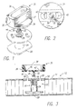
- FIG. 1 is a perspective view of the mounting fixture employed in the method and a phantom view of one type of fastener insert.
- FIG. 2 is a bottom plan view of the mounting fixture.
- FIG. 3 is a cross section of the mounting fixture and a fastener insert in a honeycomb panel.
- FIG. 4 is a cross section of the mounting fixture engaged with the fastener insert in a honeycomb panel and epoxy filling the voids.
- FIG. 5 is a view of the fastener insert and honeycomb panel in cross section showing the location of the epoxy after the mounting fixture is removed by a simple hand twisting and raising motion.
- FIG. 6 is a perspective view showing the mounting fixture about to be snapped into another type of fastener insert.
- FIG. 7 is a cross section of the honeycomb panel and fastener insert showing the flow of epoxy adhesive prior to setting.
- the mounting fixture is used after drilling or punching a hole 10 in a honeycomb panel 12 having an upper skin 14, as seen in FIG. 3.
- a Fastener insert 16 usually with mounting fixture 30 snapped together is inserted into hole 10, so that fastener head 18 fills the opening to the hole 10, but the through bores 20 and 22 in the head 18 permit entry of adhesive into the hole 10.
- the insert fastener 16 has a central body 24 which is cylindrical in shape and has an inner bore 26 which is threaded to accept a bolt.
- a flat base 28 terminates the other end.
- a mounting fixture 30 is inserted into the fastener insert by inserting a descending rod portion 32, having a disc shaped element at its end into the bore 26 of the fastener insert 16.
- the disc 38 snaps into the threads in bore 26.
- the rod 32 is integral with the base 34 on the mounting fixture 30.
- the chimney has a pair of opposite upright narrow end walls 35 flush with an edge of the base 34 and a pair of opposite upright long side walls 37 spaced apart from an edge of the base 34.
- Chimney 36 encloses bores 40 and 42 in base 34. The bores 40 and 42 penetrate the base 34 as seen in FIGS. 2 and 3.
- the base 34 of the mounting fixture 30 rests on the top surface 44 of the fastener insert head 18. Bore 40 is aligned with bore 20 and bore 42 is aligned with bore 22. Base 34 slightly overlaps head 18 of the fastener insert and the hole 10.
- Epoxy 46 or other adhesive is inserted through the chimney to either of bores 40 or 42 and is continuously pumped until the hole 10 is filled with epoxy. Thereafter, assuming epoxy is pumped down through bore 40, the epoxy begins to rise and exits bore 22 and enters the chimney 36 through bore 42. As soon as the operator sees the epoxy 46 entering the chimney 36 through the alternate bore hole the procedure is stopped and the epoxy is allowed to cure. After curing, the mounting fixture is removed by a twisting and pulling motion as seen in FIG. 5. The cured epoxy 46 as seen in FIGS. 5 and 7 fills the hole 10 of the honeycomb panel and securely holds the fastener insert 16 or 16A in the honeycomb panel 12.
- Fastener 16A has a top surface 44A with semi-circular grooves 20A and 22A on opposite edges.
- the fastener 16A has a central bore 26A with internal threads.
- the fastener has a cylindrical bottom portion 24A tapering to a bottom surface 28A.
- the mounting fixture 30 is snapped into the fastener 16A and the joined fastener 16A is then inserted into hole 10 so that the top surface 44A is flush with surface 14 of the honeycomb panel 12.
- Epoxy is pumped into one of the bores in base 34 and after filling hole 10 exits partially through the other bore in base 34 enclosed by chimney 36. After the epoxy is set, the mounting fixture is removed by a simple twisting and pulling action to break the epoxy joint between the insert and fixture.
- Bolts from aircraft auxiliary equipment or other lightweight equipment can be screwed into the fastener insert through bore 26 or 26A and thereby can be securely held in place adjacent the honeycomb panel.
- the chimney 36 employed in the mounting fixture 30 captures the overflow epoxy to keep the surface around the mounting fixture clean.
- the rod 32 and disc 38 act to prevent epoxy from contaminating the threads in bore 26 of the fastener insert.
Landscapes
- Engineering & Computer Science (AREA)
- General Engineering & Computer Science (AREA)
- Mechanical Engineering (AREA)
- Connection Of Plates (AREA)
Claims (1)
- Fixation de montage pour l'alignement et la mise en place d'une pièce rapportée de fixation (16) dans un panneau en nid d'abeille (12), la pièce rapportée de fixation (16) ayant un trou taraudé (26) et un trou d'accès d'époxy (20, 22) de chaque côté du trou taraudé (26), dans une plaque circulaire supérieure et ladite fixation de montage (30) ayant une plaque de base (34) plane circulaire dotée d'une paire de trous traversants (40, 42), une tige (32) descendant depuis une partie centrale de la plaque de base (34) et une cheminée (36) montant depuis la plaque de base (34) avec un intérieur ouvert entouré par des parois latérales (37) permettant l'accès aux trous traversants (40, 42), caractérisée en ce que la cheminée (36) a une paire de parois d'extrémité (35) étroites montantes opposées, alignées avec un bord de la base (34), et une paire de parois latérales allongées (37) montantes écartées d'un bord de la base (34), et
en ce que la tige (32) est pourvue à distance de la base (34), d'un disque (30) pour venir en prise avec les filetages du taraudage de la pièce rapportée de fixation (16).
Applications Claiming Priority (2)
| Application Number | Priority Date | Filing Date | Title |
|---|---|---|---|
| US53643390A | 1990-06-11 | 1990-06-11 | |
| US536433 | 1990-06-11 |
Publications (2)
| Publication Number | Publication Date |
|---|---|
| EP0461299A1 EP0461299A1 (fr) | 1991-12-18 |
| EP0461299B1 true EP0461299B1 (fr) | 1996-01-03 |
Family
ID=24138488
Family Applications (1)
| Application Number | Title | Priority Date | Filing Date |
|---|---|---|---|
| EP90116040A Expired - Lifetime EP0461299B1 (fr) | 1990-06-11 | 1990-08-22 | Appareillage pour fixer un élément insérable de fixation dans un panneau en nid d'abeilles |
Country Status (6)
| Country | Link |
|---|---|
| EP (1) | EP0461299B1 (fr) |
| JP (1) | JPH0792098B2 (fr) |
| AT (1) | ATE132585T1 (fr) |
| CA (1) | CA2037355C (fr) |
| DE (1) | DE69024640T2 (fr) |
| ES (1) | ES2080771T3 (fr) |
Cited By (1)
| Publication number | Priority date | Publication date | Assignee | Title |
|---|---|---|---|---|
| US11104096B2 (en) | 2018-08-30 | 2021-08-31 | The Boeing Company | Integrated fastener insert for open cellular sandwich structure and method to install |
Families Citing this family (8)
| Publication number | Priority date | Publication date | Assignee | Title |
|---|---|---|---|---|
| SE504601C2 (sv) | 1995-09-22 | 1997-03-17 | Alfa Laval Automation Ab | Förfarande samt reglersystem för friktionskomepensation |
| AT505767B1 (de) * | 2008-03-07 | 2009-04-15 | Blum Gmbh Julius | Verfahren zum vorbereiten von leichtbauplatten fur die anschliessende befestigung von beschlagen |
| DE102008020614A1 (de) * | 2008-04-24 | 2009-11-05 | Airbus Deutschland Gmbh | Verfahren zum Einsetzen einer Buchse in ein Bauteil und Buchse |
| EP2610505A1 (fr) * | 2011-12-30 | 2013-07-03 | AGUSTAWESTLAND S.p.A. | Insert conducteur de l'électricité, et outil et procédé d'application d'un tel insert dans un élément de support |
| FR2986287B1 (fr) * | 2012-01-30 | 2015-04-24 | Bollhoff Otalu Sa | Accessoire d'assemblage d'un materiel a une structure composite, ensemble pour doter une structure composite d'un tel accessoire et procede de fixation d'un tel accessoire |
| EP2909004B1 (fr) * | 2012-10-17 | 2019-01-23 | RUAG Schweiz AG | Procédé et système d'implantation d'un élément dans un panneau |
| US9457537B1 (en) | 2013-11-26 | 2016-10-04 | Hrl Laboratories, Llc | Methods for embedding fasteners in an open cellular sandwich structure |
| CN106194931B (zh) * | 2015-05-07 | 2018-07-06 | 哈尔滨飞机工业集团有限责任公司 | 一种在夹层结构中反向安装镶嵌衬套的方法 |
Family Cites Families (5)
| Publication number | Priority date | Publication date | Assignee | Title |
|---|---|---|---|---|
| US3282015A (en) * | 1962-04-20 | 1966-11-01 | Frederick W Rohe | Moldable insert fastener with dual potting ports in head |
| US3621557A (en) * | 1969-06-06 | 1971-11-23 | Rex Chainbelt Inc | Insert for sandwich panels and method of installation |
| DE2750829C2 (de) * | 1977-11-14 | 1982-12-16 | Camloc Fastener Gmbh, 6233 Kelkheim | Vorrichtung zum Einsetzen und Vergießen eines in einer Leichtbau-Schichtverbundplatte mit Vergußmasse zu befestigenden Gewindedübels o.dgl. |
| DE3042432C2 (de) * | 1980-11-11 | 1984-11-15 | Messerschmitt-Bölkow-Blohm GmbH, 8000 München | Befestigungsvorrichtung für eine Sandwichplatte zur Aufnahme von Befestigungsschrauben mit einem Spreizdübel und Gewindeeinsatz |
| US4800643A (en) * | 1987-02-02 | 1989-01-31 | Atr International, Inc. | Method of mounting a bolt in lightweight panels |
-
1990
- 1990-08-22 ES ES90116040T patent/ES2080771T3/es not_active Expired - Lifetime
- 1990-08-22 DE DE69024640T patent/DE69024640T2/de not_active Expired - Fee Related
- 1990-08-22 AT AT90116040T patent/ATE132585T1/de active
- 1990-08-22 EP EP90116040A patent/EP0461299B1/fr not_active Expired - Lifetime
-
1991
- 1991-02-28 CA CA002037355A patent/CA2037355C/fr not_active Expired - Fee Related
- 1991-04-18 JP JP3112194A patent/JPH0792098B2/ja not_active Expired - Lifetime
Cited By (1)
| Publication number | Priority date | Publication date | Assignee | Title |
|---|---|---|---|---|
| US11104096B2 (en) | 2018-08-30 | 2021-08-31 | The Boeing Company | Integrated fastener insert for open cellular sandwich structure and method to install |
Also Published As
| Publication number | Publication date |
|---|---|
| CA2037355A1 (fr) | 1991-12-12 |
| EP0461299A1 (fr) | 1991-12-18 |
| JPH0792098B2 (ja) | 1995-10-09 |
| DE69024640T2 (de) | 1996-06-20 |
| JPH04231711A (ja) | 1992-08-20 |
| ATE132585T1 (de) | 1996-01-15 |
| ES2080771T3 (es) | 1996-02-16 |
| CA2037355C (fr) | 1995-05-23 |
| DE69024640D1 (de) | 1996-02-15 |
Similar Documents
| Publication | Publication Date | Title |
|---|---|---|
| US5240543A (en) | Apparatus for and method of seating a fastener insert in a honeycomb panel | |
| EP0726372B1 (fr) | Elément de fixation pour produits d'isolation | |
| DE602009022922C5 (de) | Verbinderanordnung | |
| US5037259A (en) | Nut with sleeve lock | |
| DE69915942T2 (de) | Halterungsvorrichtung für das Armaturenbrett | |
| DE3012899A1 (de) | Vibrationen daempfendes befestigungsglied | |
| ATE47469T1 (de) | Vorrichtung zum loesbaren verbinden zweier profilstaebe. | |
| SE469237B (sv) | Anordning foer justerbar infaestning av doerrkarmar, foensterkarmar och liknande element mot ett baerande element | |
| CA2037355C (fr) | Methode d'implantation d'un insert-fixation dans un panneau alveolaire | |
| CA2100834A1 (fr) | Manchon pour l'assemblage d'une poutre betonnee | |
| DE102004018736A1 (de) | Verbindungselement | |
| KR19980033114A (ko) | 모듈 지지 구조체 | |
| US20060175595A1 (en) | Post-to-base attachment | |
| EP0723506A1 (fr) | Gllissieres de porte-bagages monte sur un toit de vehicule | |
| ATE102109T1 (de) | Adaptor zum aufschrauben oder abschrauben von einem verbindungselement mit gewinde. | |
| EP0965721A1 (fr) | Fixation pour élément de vitrage isolant | |
| DE3815176C1 (fr) | ||
| ATE125908T1 (de) | Schraubverbindung zwischen einer profilschiene und einem beschlag oder einem sonstigen bauteil. | |
| DE2809704C2 (de) | Mittelholmtreppe | |
| DE29608334U1 (de) | Befestigungsmittel | |
| DE60118445T2 (de) | Verfahren und Bausatz zur Befestigung von Tafeln mit doppelten Flanken | |
| JPS6328319Y2 (fr) | ||
| DE19621893C1 (de) | Montageverbinder | |
| CH681237A5 (fr) | ||
| CH639167A5 (en) | Stair |
Legal Events
| Date | Code | Title | Description |
|---|---|---|---|
| PUAI | Public reference made under article 153(3) epc to a published international application that has entered the european phase |
Free format text: ORIGINAL CODE: 0009012 |
|
| 17P | Request for examination filed |
Effective date: 19910610 |
|
| AK | Designated contracting states |
Kind code of ref document: A1 Designated state(s): AT BE CH DE ES FR GB GR IT LI LU NL SE |
|
| 17Q | First examination report despatched |
Effective date: 19930303 |
|
| GRAA | (expected) grant |
Free format text: ORIGINAL CODE: 0009210 |
|
| AK | Designated contracting states |
Kind code of ref document: B1 Designated state(s): AT BE CH DE ES FR GB GR IT LI LU NL SE |
|
| PG25 | Lapsed in a contracting state [announced via postgrant information from national office to epo] |
Ref country code: GR Free format text: LAPSE BECAUSE OF FAILURE TO SUBMIT A TRANSLATION OF THE DESCRIPTION OR TO PAY THE FEE WITHIN THE PRESCRIBED TIME-LIMIT Effective date: 19960103 |
|
| REF | Corresponds to: |
Ref document number: 132585 Country of ref document: AT Date of ref document: 19960115 Kind code of ref document: T |
|
| REF | Corresponds to: |
Ref document number: 69024640 Country of ref document: DE Date of ref document: 19960215 |
|
| REG | Reference to a national code |
Ref country code: ES Ref legal event code: FG2A Ref document number: 2080771 Country of ref document: ES Kind code of ref document: T3 |
|
| ET | Fr: translation filed | ||
| REG | Reference to a national code |
Ref country code: CH Ref legal event code: NV Representative=s name: BOVARD AG PATENTANWAELTE |
|
| ITF | It: translation for a ep patent filed | ||
| PLBE | No opposition filed within time limit |
Free format text: ORIGINAL CODE: 0009261 |
|
| STAA | Information on the status of an ep patent application or granted ep patent |
Free format text: STATUS: NO OPPOSITION FILED WITHIN TIME LIMIT |
|
| 26N | No opposition filed | ||
| REG | Reference to a national code |
Ref country code: GB Ref legal event code: 732E |
|
| NLS | Nl: assignments of ep-patents |
Owner name: AAR MANUFACTURING GROUP, INC. AN ILLINOIS CORPORAT |
|
| REG | Reference to a national code |
Ref country code: CH Ref legal event code: PFA Free format text: ATR INTERNATIONAL, INC. TRANSFER- AAR MANUFACTURING GROUP, INC. |
|
| REG | Reference to a national code |
Ref country code: ES Ref legal event code: PC2A |
|
| REG | Reference to a national code |
Ref country code: FR Ref legal event code: TP |
|
| PGFP | Annual fee paid to national office [announced via postgrant information from national office to epo] |
Ref country code: DE Payment date: 20000629 Year of fee payment: 11 |
|
| PGFP | Annual fee paid to national office [announced via postgrant information from national office to epo] |
Ref country code: GB Payment date: 20000717 Year of fee payment: 11 Ref country code: CH Payment date: 20000717 Year of fee payment: 11 |
|
| PGFP | Annual fee paid to national office [announced via postgrant information from national office to epo] |
Ref country code: LU Payment date: 20000724 Year of fee payment: 11 Ref country code: AT Payment date: 20000724 Year of fee payment: 11 |
|
| PGFP | Annual fee paid to national office [announced via postgrant information from national office to epo] |
Ref country code: NL Payment date: 20000725 Year of fee payment: 11 |
|
| PGFP | Annual fee paid to national office [announced via postgrant information from national office to epo] |
Ref country code: SE Payment date: 20000726 Year of fee payment: 11 |
|
| PGFP | Annual fee paid to national office [announced via postgrant information from national office to epo] |
Ref country code: BE Payment date: 20000728 Year of fee payment: 11 |
|
| PGFP | Annual fee paid to national office [announced via postgrant information from national office to epo] |
Ref country code: FR Payment date: 20000801 Year of fee payment: 11 |
|
| PGFP | Annual fee paid to national office [announced via postgrant information from national office to epo] |
Ref country code: ES Payment date: 20000825 Year of fee payment: 11 |
|
| PG25 | Lapsed in a contracting state [announced via postgrant information from national office to epo] |
Ref country code: LU Free format text: LAPSE BECAUSE OF NON-PAYMENT OF DUE FEES Effective date: 20010822 Ref country code: GB Free format text: LAPSE BECAUSE OF NON-PAYMENT OF DUE FEES Effective date: 20010822 Ref country code: AT Free format text: LAPSE BECAUSE OF NON-PAYMENT OF DUE FEES Effective date: 20010822 |
|
| PG25 | Lapsed in a contracting state [announced via postgrant information from national office to epo] |
Ref country code: SE Free format text: LAPSE BECAUSE OF NON-PAYMENT OF DUE FEES Effective date: 20010823 Ref country code: ES Free format text: LAPSE BECAUSE OF NON-PAYMENT OF DUE FEES Effective date: 20010823 |
|
| PG25 | Lapsed in a contracting state [announced via postgrant information from national office to epo] |
Ref country code: LI Free format text: LAPSE BECAUSE OF NON-PAYMENT OF DUE FEES Effective date: 20010831 Ref country code: CH Free format text: LAPSE BECAUSE OF NON-PAYMENT OF DUE FEES Effective date: 20010831 Ref country code: BE Free format text: LAPSE BECAUSE OF NON-PAYMENT OF DUE FEES Effective date: 20010831 |
|
| BERE | Be: lapsed |
Owner name: AAR MFG GROUP INC. Effective date: 20010831 |
|
| PG25 | Lapsed in a contracting state [announced via postgrant information from national office to epo] |
Ref country code: NL Free format text: LAPSE BECAUSE OF NON-PAYMENT OF DUE FEES Effective date: 20020301 |
|
| EUG | Se: european patent has lapsed |
Ref document number: 90116040.8 |
|
| REG | Reference to a national code |
Ref country code: CH Ref legal event code: PL |
|
| GBPC | Gb: european patent ceased through non-payment of renewal fee |
Effective date: 20010822 |
|
| PG25 | Lapsed in a contracting state [announced via postgrant information from national office to epo] |
Ref country code: FR Free format text: LAPSE BECAUSE OF NON-PAYMENT OF DUE FEES Effective date: 20020430 |
|
| NLV4 | Nl: lapsed or anulled due to non-payment of the annual fee |
Effective date: 20020301 |
|
| PG25 | Lapsed in a contracting state [announced via postgrant information from national office to epo] |
Ref country code: DE Free format text: LAPSE BECAUSE OF NON-PAYMENT OF DUE FEES Effective date: 20020501 |
|
| REG | Reference to a national code |
Ref country code: FR Ref legal event code: ST |
|
| REG | Reference to a national code |
Ref country code: ES Ref legal event code: FD2A Effective date: 20020911 |
|
| PG25 | Lapsed in a contracting state [announced via postgrant information from national office to epo] |
Ref country code: IT Free format text: LAPSE BECAUSE OF NON-PAYMENT OF DUE FEES Effective date: 20050822 |