EP0461365A1 - Procédé et appareil pour alimenter un moule de compression en matière plastique - Google Patents
Procédé et appareil pour alimenter un moule de compression en matière plastique Download PDFInfo
- Publication number
- EP0461365A1 EP0461365A1 EP91106302A EP91106302A EP0461365A1 EP 0461365 A1 EP0461365 A1 EP 0461365A1 EP 91106302 A EP91106302 A EP 91106302A EP 91106302 A EP91106302 A EP 91106302A EP 0461365 A1 EP0461365 A1 EP 0461365A1
- Authority
- EP
- European Patent Office
- Prior art keywords
- extrudate
- belt
- transport
- controlled
- heated
- Prior art date
- Legal status (The legal status is an assumption and is not a legal conclusion. Google has not performed a legal analysis and makes no representation as to the accuracy of the status listed.)
- Granted
Links
Images

Classifications
-
- B—PERFORMING OPERATIONS; TRANSPORTING
- B29—WORKING OF PLASTICS; WORKING OF SUBSTANCES IN A PLASTIC STATE IN GENERAL
- B29B—PREPARATION OR PRETREATMENT OF THE MATERIAL TO BE SHAPED; MAKING GRANULES OR PREFORMS; RECOVERY OF PLASTICS OR OTHER CONSTITUENTS OF WASTE MATERIAL CONTAINING PLASTICS
- B29B11/00—Making preforms
- B29B11/06—Making preforms by moulding the material
- B29B11/10—Extrusion moulding
-
- B—PERFORMING OPERATIONS; TRANSPORTING
- B29—WORKING OF PLASTICS; WORKING OF SUBSTANCES IN A PLASTIC STATE IN GENERAL
- B29C—SHAPING OR JOINING OF PLASTICS; SHAPING OF MATERIAL IN A PLASTIC STATE, NOT OTHERWISE PROVIDED FOR; AFTER-TREATMENT OF THE SHAPED PRODUCTS, e.g. REPAIRING
- B29C31/00—Handling, e.g. feeding of the material to be shaped, storage of plastics material before moulding; Automation, i.e. automated handling lines in plastics processing plants, e.g. using manipulators or robots
- B29C31/04—Feeding of the material to be moulded, e.g. into a mould cavity
- B29C31/06—Feeding of the material to be moulded, e.g. into a mould cavity in measured doses, e.g. by weighting
-
- B—PERFORMING OPERATIONS; TRANSPORTING
- B29—WORKING OF PLASTICS; WORKING OF SUBSTANCES IN A PLASTIC STATE IN GENERAL
- B29C—SHAPING OR JOINING OF PLASTICS; SHAPING OF MATERIAL IN A PLASTIC STATE, NOT OTHERWISE PROVIDED FOR; AFTER-TREATMENT OF THE SHAPED PRODUCTS, e.g. REPAIRING
- B29C31/00—Handling, e.g. feeding of the material to be shaped, storage of plastics material before moulding; Automation, i.e. automated handling lines in plastics processing plants, e.g. using manipulators or robots
- B29C31/04—Feeding of the material to be moulded, e.g. into a mould cavity
- B29C31/08—Feeding of the material to be moulded, e.g. into a mould cavity of preforms to be moulded, e.g. tablets, fibre reinforced preforms, extruded ribbons, tubes or profiles; Manipulating means specially adapted for feeding preforms, e.g. supports conveyors
-
- B—PERFORMING OPERATIONS; TRANSPORTING
- B29—WORKING OF PLASTICS; WORKING OF SUBSTANCES IN A PLASTIC STATE IN GENERAL
- B29C—SHAPING OR JOINING OF PLASTICS; SHAPING OF MATERIAL IN A PLASTIC STATE, NOT OTHERWISE PROVIDED FOR; AFTER-TREATMENT OF THE SHAPED PRODUCTS, e.g. REPAIRING
- B29C43/00—Compression moulding, i.e. applying external pressure to flow the moulding material; Apparatus therefor
- B29C43/32—Component parts, details or accessories; Auxiliary operations
- B29C43/34—Feeding the material to the mould or the compression means
-
- B—PERFORMING OPERATIONS; TRANSPORTING
- B29—WORKING OF PLASTICS; WORKING OF SUBSTANCES IN A PLASTIC STATE IN GENERAL
- B29C—SHAPING OR JOINING OF PLASTICS; SHAPING OF MATERIAL IN A PLASTIC STATE, NOT OTHERWISE PROVIDED FOR; AFTER-TREATMENT OF THE SHAPED PRODUCTS, e.g. REPAIRING
- B29C48/00—Extrusion moulding, i.e. expressing the moulding material through a die or nozzle which imparts the desired form; Apparatus therefor
- B29C48/03—Extrusion moulding, i.e. expressing the moulding material through a die or nozzle which imparts the desired form; Apparatus therefor characterised by the shape of the extruded material at extrusion
- B29C48/05—Filamentary, e.g. strands
-
- B—PERFORMING OPERATIONS; TRANSPORTING
- B29—WORKING OF PLASTICS; WORKING OF SUBSTANCES IN A PLASTIC STATE IN GENERAL
- B29C—SHAPING OR JOINING OF PLASTICS; SHAPING OF MATERIAL IN A PLASTIC STATE, NOT OTHERWISE PROVIDED FOR; AFTER-TREATMENT OF THE SHAPED PRODUCTS, e.g. REPAIRING
- B29C48/00—Extrusion moulding, i.e. expressing the moulding material through a die or nozzle which imparts the desired form; Apparatus therefor
- B29C48/03—Extrusion moulding, i.e. expressing the moulding material through a die or nozzle which imparts the desired form; Apparatus therefor characterised by the shape of the extruded material at extrusion
- B29C48/07—Flat, e.g. panels
- B29C48/08—Flat, e.g. panels flexible, e.g. films
-
- B—PERFORMING OPERATIONS; TRANSPORTING
- B29—WORKING OF PLASTICS; WORKING OF SUBSTANCES IN A PLASTIC STATE IN GENERAL
- B29C—SHAPING OR JOINING OF PLASTICS; SHAPING OF MATERIAL IN A PLASTIC STATE, NOT OTHERWISE PROVIDED FOR; AFTER-TREATMENT OF THE SHAPED PRODUCTS, e.g. REPAIRING
- B29C48/00—Extrusion moulding, i.e. expressing the moulding material through a die or nozzle which imparts the desired form; Apparatus therefor
- B29C48/03—Extrusion moulding, i.e. expressing the moulding material through a die or nozzle which imparts the desired form; Apparatus therefor characterised by the shape of the extruded material at extrusion
- B29C48/09—Articles with cross-sections having partially or fully enclosed cavities, e.g. pipes or channels
- B29C48/11—Articles with cross-sections having partially or fully enclosed cavities, e.g. pipes or channels comprising two or more partially or fully enclosed cavities, e.g. honeycomb-shaped
-
- B—PERFORMING OPERATIONS; TRANSPORTING
- B29—WORKING OF PLASTICS; WORKING OF SUBSTANCES IN A PLASTIC STATE IN GENERAL
- B29C—SHAPING OR JOINING OF PLASTICS; SHAPING OF MATERIAL IN A PLASTIC STATE, NOT OTHERWISE PROVIDED FOR; AFTER-TREATMENT OF THE SHAPED PRODUCTS, e.g. REPAIRING
- B29C48/00—Extrusion moulding, i.e. expressing the moulding material through a die or nozzle which imparts the desired form; Apparatus therefor
- B29C48/25—Component parts, details or accessories; Auxiliary operations
- B29C48/30—Extrusion nozzles or dies
- B29C48/305—Extrusion nozzles or dies having a wide opening, e.g. for forming sheets
-
- B—PERFORMING OPERATIONS; TRANSPORTING
- B29—WORKING OF PLASTICS; WORKING OF SUBSTANCES IN A PLASTIC STATE IN GENERAL
- B29C—SHAPING OR JOINING OF PLASTICS; SHAPING OF MATERIAL IN A PLASTIC STATE, NOT OTHERWISE PROVIDED FOR; AFTER-TREATMENT OF THE SHAPED PRODUCTS, e.g. REPAIRING
- B29C48/00—Extrusion moulding, i.e. expressing the moulding material through a die or nozzle which imparts the desired form; Apparatus therefor
- B29C48/25—Component parts, details or accessories; Auxiliary operations
- B29C48/78—Thermal treatment of the extrusion moulding material or of preformed parts or layers, e.g. by heating or cooling
- B29C48/80—Thermal treatment of the extrusion moulding material or of preformed parts or layers, e.g. by heating or cooling at the plasticising zone, e.g. by heating cylinders
- B29C48/83—Heating or cooling the cylinders
- B29C48/832—Heating
-
- B—PERFORMING OPERATIONS; TRANSPORTING
- B29—WORKING OF PLASTICS; WORKING OF SUBSTANCES IN A PLASTIC STATE IN GENERAL
- B29C—SHAPING OR JOINING OF PLASTICS; SHAPING OF MATERIAL IN A PLASTIC STATE, NOT OTHERWISE PROVIDED FOR; AFTER-TREATMENT OF THE SHAPED PRODUCTS, e.g. REPAIRING
- B29C48/00—Extrusion moulding, i.e. expressing the moulding material through a die or nozzle which imparts the desired form; Apparatus therefor
- B29C48/25—Component parts, details or accessories; Auxiliary operations
- B29C48/78—Thermal treatment of the extrusion moulding material or of preformed parts or layers, e.g. by heating or cooling
- B29C48/86—Thermal treatment of the extrusion moulding material or of preformed parts or layers, e.g. by heating or cooling at the nozzle zone
-
- B—PERFORMING OPERATIONS; TRANSPORTING
- B29—WORKING OF PLASTICS; WORKING OF SUBSTANCES IN A PLASTIC STATE IN GENERAL
- B29C—SHAPING OR JOINING OF PLASTICS; SHAPING OF MATERIAL IN A PLASTIC STATE, NOT OTHERWISE PROVIDED FOR; AFTER-TREATMENT OF THE SHAPED PRODUCTS, e.g. REPAIRING
- B29C48/00—Extrusion moulding, i.e. expressing the moulding material through a die or nozzle which imparts the desired form; Apparatus therefor
- B29C48/25—Component parts, details or accessories; Auxiliary operations
- B29C48/78—Thermal treatment of the extrusion moulding material or of preformed parts or layers, e.g. by heating or cooling
- B29C48/86—Thermal treatment of the extrusion moulding material or of preformed parts or layers, e.g. by heating or cooling at the nozzle zone
- B29C48/865—Heating
-
- B—PERFORMING OPERATIONS; TRANSPORTING
- B29—WORKING OF PLASTICS; WORKING OF SUBSTANCES IN A PLASTIC STATE IN GENERAL
- B29C—SHAPING OR JOINING OF PLASTICS; SHAPING OF MATERIAL IN A PLASTIC STATE, NOT OTHERWISE PROVIDED FOR; AFTER-TREATMENT OF THE SHAPED PRODUCTS, e.g. REPAIRING
- B29C48/00—Extrusion moulding, i.e. expressing the moulding material through a die or nozzle which imparts the desired form; Apparatus therefor
- B29C48/25—Component parts, details or accessories; Auxiliary operations
- B29C48/78—Thermal treatment of the extrusion moulding material or of preformed parts or layers, e.g. by heating or cooling
- B29C48/86—Thermal treatment of the extrusion moulding material or of preformed parts or layers, e.g. by heating or cooling at the nozzle zone
- B29C48/87—Cooling
-
- B—PERFORMING OPERATIONS; TRANSPORTING
- B29—WORKING OF PLASTICS; WORKING OF SUBSTANCES IN A PLASTIC STATE IN GENERAL
- B29C—SHAPING OR JOINING OF PLASTICS; SHAPING OF MATERIAL IN A PLASTIC STATE, NOT OTHERWISE PROVIDED FOR; AFTER-TREATMENT OF THE SHAPED PRODUCTS, e.g. REPAIRING
- B29C48/00—Extrusion moulding, i.e. expressing the moulding material through a die or nozzle which imparts the desired form; Apparatus therefor
- B29C48/25—Component parts, details or accessories; Auxiliary operations
- B29C48/88—Thermal treatment of the stream of extruded material, e.g. cooling
- B29C48/91—Heating, e.g. for cross linking
-
- B—PERFORMING OPERATIONS; TRANSPORTING
- B29—WORKING OF PLASTICS; WORKING OF SUBSTANCES IN A PLASTIC STATE IN GENERAL
- B29C—SHAPING OR JOINING OF PLASTICS; SHAPING OF MATERIAL IN A PLASTIC STATE, NOT OTHERWISE PROVIDED FOR; AFTER-TREATMENT OF THE SHAPED PRODUCTS, e.g. REPAIRING
- B29C2949/00—Indexing scheme relating to blow-moulding
- B29C2949/07—Preforms or parisons characterised by their configuration
- B29C2949/081—Specified dimensions, e.g. values or ranges
- B29C2949/0811—Wall thickness
-
- B—PERFORMING OPERATIONS; TRANSPORTING
- B29—WORKING OF PLASTICS; WORKING OF SUBSTANCES IN A PLASTIC STATE IN GENERAL
- B29C—SHAPING OR JOINING OF PLASTICS; SHAPING OF MATERIAL IN A PLASTIC STATE, NOT OTHERWISE PROVIDED FOR; AFTER-TREATMENT OF THE SHAPED PRODUCTS, e.g. REPAIRING
- B29C48/00—Extrusion moulding, i.e. expressing the moulding material through a die or nozzle which imparts the desired form; Apparatus therefor
-
- B—PERFORMING OPERATIONS; TRANSPORTING
- B29—WORKING OF PLASTICS; WORKING OF SUBSTANCES IN A PLASTIC STATE IN GENERAL
- B29K—INDEXING SCHEME ASSOCIATED WITH SUBCLASSES B29B, B29C OR B29D, RELATING TO MOULDING MATERIALS OR TO MATERIALS FOR MOULDS, REINFORCEMENTS, FILLERS OR PREFORMED PARTS, e.g. INSERTS
- B29K2101/00—Use of unspecified macromolecular compounds as moulding material
- B29K2101/12—Thermoplastic materials
-
- B—PERFORMING OPERATIONS; TRANSPORTING
- B29—WORKING OF PLASTICS; WORKING OF SUBSTANCES IN A PLASTIC STATE IN GENERAL
- B29K—INDEXING SCHEME ASSOCIATED WITH SUBCLASSES B29B, B29C OR B29D, RELATING TO MOULDING MATERIALS OR TO MATERIALS FOR MOULDS, REINFORCEMENTS, FILLERS OR PREFORMED PARTS, e.g. INSERTS
- B29K2105/00—Condition, form or state of moulded material or of the material to be shaped
- B29K2105/25—Solid
- B29K2105/253—Preform
- B29K2105/256—Sheets, plates, blanks or films
-
- B—PERFORMING OPERATIONS; TRANSPORTING
- B29—WORKING OF PLASTICS; WORKING OF SUBSTANCES IN A PLASTIC STATE IN GENERAL
- B29K—INDEXING SCHEME ASSOCIATED WITH SUBCLASSES B29B, B29C OR B29D, RELATING TO MOULDING MATERIALS OR TO MATERIALS FOR MOULDS, REINFORCEMENTS, FILLERS OR PREFORMED PARTS, e.g. INSERTS
- B29K2105/00—Condition, form or state of moulded material or of the material to be shaped
- B29K2105/26—Scrap or recycled material
Definitions
- the invention relates to a method and a device for loading a press mold with extruded plastic, in particular using free-flowing crushed recycled plastics, which are fed to the extruder in a predetermined mixing ratio, optionally with the addition of a thermoplastic as a binder, with heating and possibly degassing blended, extruded through the exit of a heated extrusion die, and in measured extrudate portions using a heated transport device can be fed to a compression mold.
- the disadvantage here is that the extrudate portion is deposited in a lump-like manner, ie without having a specific shape, in a loading trough of the compression molding tool.
- the pressing pressure required to form the final plastic product is therefore considerable, so that large-sized presses must be used for the pressing process, with a corresponding expenditure of pressing energy.
- the shape of the extrudate portion must be considerably deformed during pressing, in particular to form a flat plastic end product, since large flow paths have to be covered to fill the feed trough.
- the associated shear forces sometimes lead to considerable internal stresses in the finished plastic part, which often brings about deformation or warping of the molded plastic part and thus results in unusable parts.
- complex tempering measures are required while the end product is still in the press mold tool, which considerably increases the device and energy expenditure of the press / press mold tool.
- the invention has for its object to provide a method and an apparatus of the type mentioned, in which an improvement in the loading of the compression mold is to be achieved, while reducing the necessary pressing forces during the pressing process and the residual stresses in the finished pressed plastic part are reduced.
- the invention provides as a method that the extrudate strand leaving the extrusion die is placed in a meandering manner next to and / or on top of one another on a temperature-controlled and controlled oscillating shelf, namely on a base surface that corresponds, for example, to the loading area of the plastic part to be molded in the press mold or to a partial area thereof and its desired molding compound distribution and is separated off when a predetermined extrudate portion size is reached, with several extrudate portions possibly being placed on the tray and fed to the transport device.
- extrudate portions that is to say the extrudate blanks
- the geometric shape of the finished plastic part that is to say the creation of an extrudate portion, which in particular is largely flat, the width of which depends in part on the exit cross-sectional shape of the extrusion die, and its length , Width, and local thickness is dependent on the oscillation speed and the oscillation stroke during an oscillation of the deposit during the depositing process of the extrudate strand.
- a meandering stacking of individual strand layers to form a flat structure brings great advantages in the final shaping within the press tool in the press, since shorter flow paths are required to fill the feed trough in the press tool, which means that there is almost no residual stress in the finished plastic part of "frozen" shear forces.
- the weight of the extrudate strand deposited on the tray is detected and, when a predetermined target value is reached, a signal is sent to a separating device for severing the extrudate strand, after which the weight of the extrudate portion deposited is captured and is discarded in the event of a deviation by a predetermined tolerance amount, and the target value is corrected or a temporary target value is set, if necessary.
- the method can be electronically controlled and monitored, that is to say can be carried out automatically, in particular by means of a central electronic control and control device, with all of the results thereof Rationalization and automation advantages that a centrally controlled system brings with it.
- the oscillation speed of the deposit and the oscillation stroke (path) can be changed while the extrudate strand is being deposited.
- the oscillation speed is selected to be equal to the exit speed of the extrudate strand from the extrusion tool, ie, the material-specific loading speed of the extruder.
- the tax expenditure for the production of a flat extrudate blank by means of the tray can be considerably reduced by the fact that the extrudate strand leaving the extrusion tool without impulses can be fed to the tray in the form of a belt which may have a variable width and / or thickness. It is technically sensible and easy to handle that the extrudate strand with a width of about 100-1,400 mm and a thickness of 1-15 mm can leave the outlet of the extrusion die. By optimizing the thickness and width, the necessary oscillation strokes can be reduced in order to achieve an extrudate blank that conforms to the shape and the wear required for the device required for this.
- a longitudinally slotted tubular nozzle can be provided as the extrusion tool, by means of which the extrudate strand is formed.
- the outlet slot of the tubular nozzle is followed by a separating device having at least one cutting element, to which a controlled oscillating shelf with weighing device and possibly temperature-controlled temperature control device is connected, which in turn is followed by a heated transport device for transporting at least one measured extrudate portion into one or more Press molds of at least one press.
- the heated transport device ensures that the outer skin of the extrudate portion to be guided to the die does not cool down during the transport process and that different flow properties then arise in the extrudate blank to be pressed during the pressing. This results in a significant improvement in the quality of the plastic parts produced.
- the device can have a central electronic control and regulating device for regulating, monitoring and control, which can control and / or regulate all device components and the presses fully automatically and, if necessary, coordinate with one another. This is preferably ensured by means of a programmable logic controller.
- the pipe nozzle serving as the extrusion tool can have a heated cylinder which can be interchangeably flanged onto the extruder and has a jacket-side outlet slot running parallel to the cylinder's longitudinal axis, and a protruding, optionally heated, displacement body projecting into the cylinder from outside one end of the cylinder to the extruder-side tool connection flange is conical or parabolic.
- the outlet slot is heated in a particularly advantageous manner; its length can be approximately 100-1400 mm and its slot width approximately 3-15 mm.
- the pipe nozzle it is provided that it may have a heated orifice for adjusting the clear slot length and / or width, whereby replacement of individual pipe nozzles to change the necessary extrudate width or thickness can be reduced to a minimum .
- the screen can consist of steel mask elements slidably held on the outside of the cylinder.
- the separating device can be operated mechanically, hydraulically or pneumatically, by means of Weighing device controlled lifting cylinder, which preferably arranged parallel to the extrusion tool has a longitudinally displaceable cutting knife.
- the separating device provides that it can have two cutting knives which run parallel to one another and are arranged on both sides of the outlet slot and which can be suddenly delivered to and separated from one another for severing the extrudate strand, the separating device being controlled by the weighing device.
- the control can be carried out either directly by the weighing device or by the control and control device, which is also coupled to the weighing device.
- the cutting knives are expediently heated and / or non-stick coated.
- a scale in particular a belt scale, can be provided as a tray, which can have a non-stick coated endless storage tape, in particular a PTFE-coated or silicone tape, which rolls by means of a controlled drive, in particular with a stepping or servo motor is movable in two directions, which requires less control effort for the oscillating movement of the tray.
- a non-stick coated endless storage tape in particular a PTFE-coated or silicone tape
- the belt scale can expediently have a fast forward and return, the belt speed being infinitely variable in order to ensure an adaptation to the exit speed of the extrudate strand from the tubular nozzle, which is dependent on the material composition and the loading speed of the extruder.
- the temperature control device can be formed by flexible, inductively heatable, optionally thermostatically controlled heating tapes or wires which are arranged in the deposit belt.
- infrared emitters can also be provided which are directed onto the storage belt.
- the weighing device can consist of a zero-tare strain gauge weighing cell arrangement which interacts with the belt guide frame accommodated in a storage table, which has the rollers and the storage belt, and possibly has a pulse generator for the cutting device which, when the desired Weight of the deposited extrudate strand triggers the cutting process.
- the tape guide frame or the tray table can be slidably mounted transversely to the tape transport direction and by means of an adjustable Drive, in particular a stepper or servo motor, can be moved in an oscillating manner, as a result of which several extrudate portions can be deposited next to one another or offset to one another or, if superimposed with the oscillating movement of the deposit belt, any contours can be controlled to produce a specially shaped extrudate blank.
- an adjustable Drive in particular a stepper or servo motor
- At least one transport table having the conveyor belt can be advantageously provided, which can be moved by motor between a receiving position adjoining the belt scale and at least one loading position, in which is a locally targeted loading of the open mold, whereby a variable and adaptable transport device is formed.
- the transport device can have a modular design and have at least two transport tables, which can be moved alternately in the receiving position on the belt scale and when loaded with at least one extrudate portion in a controlled manner into a loading position on at least one press in which at least one loading trough or a sub-area of which at least one press mold can be fed with at least one extrudate portion, which means that considerably shorter press feed rates can be achieved.
- extrudate portions can either be placed locally in different zones of a loading trough or one extrudate portion each in one or more loading troughs of a compression molding tool, without having to move the transport table each time in the receiving position for receiving an extrudate portion and then again in a controlled manner to move to the specific loading position.
- the belt speeds of the transport table in the receiving position and that of the storage belt of the belt scale can expediently be synchronized for the stretch-free transfer of the extrudate portions.
- the transport table can have a belt guide frame that receives the conveyor belt, which can be moved on the transport table by means of a motor and, if necessary, can be aligned, in particular tilted, so that at least the end region of the conveyor belt can be attached to or via the compression mold to be loaded is telescopically deliverable and retractable for targeted loading, so that the loading trough can be optimally loaded in the compression mold.
- the drive of the The belt guide frame and the drive of the conveyor belt can be synchronized, so that the belt guide frame can be retracted with simultaneous loading movement of the conveyor belt for the exact placement of the extrudate portion (s) in the compression mold, whereby the contour of the extrudate portion (s) when introduced into the respective loading trough preserved.
- the conditioning device can, in a preferred embodiment, be formed by an insulation hood with a motor-controlled interior that can be moved up and down via the transport table in the receiving position be; the heating is carried out in particular by heating plates or radiant heaters and is preferably controlled by a thermostat.
- each transport table can have such an insulating hood, which can be held by means of a suspension above the conveyor belt so that the extrudate portions can be tempered even during the movement of the transport table into the respective loading position is.
- a motor-driven disposal belt with subsequent extrudate regeneration device in particular a plastic comminution device, should be provided at the end of the belt scale opposite the transport device, by means of which incorrectly produced extrudate portions are excreted after the depositing process and passed on to the extrusion process again at a later point in time can be, whereby the reject of defective plastic molded parts can be reduced even before the pressing process and additional energy is saved.
- a motor-driven removal gripper which preferably has one rotational and two translational degrees of freedom of movement, can be provided in the removal device open mold for targeted removal of the plastic part, in particular by means of a vacuum suction device, can be retracted and withdrawn, so that manual removal of the still hot plastic pressed parts by an operator is not required.
- a removal belt can be provided in a structurally simple manner for the targeted removal of the plastic pressed parts open press mold can be designed to be able to be moved in and out by means of a motor, on the endless belt, possibly non-stick coated, rotating around motor-driven rollers, the pressed plastic part after ejection from the press tool can be picked up and transported.
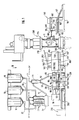
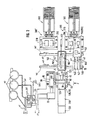
- FIG. 1 and 2 a plant is shown in a schematic representation for the production of, in particular, flat plastic molded parts from a recycled plastic extrudate mixture.
- the system has storage containers 10, in which free-flowing shredded recycling plastics are bunkered, preferably different types of waste plastics that have been obtained as waste in other processing processes, for example, or plastic-granulate mixtures of various compositions, possibly with fillers such as aluminum chips and the like.
- the material from the individual containers 10 is fed via conveying lines 20, each with conveying devices 25 equipped with dust filters, each of which is connected via suction lines 22 to a drive 24, not shown, in the form of high-performance fans (suction conveying).
- the plastic-granulate mixture passes into a mixing device 30, in which the plastic granules are mixed in a predetermined ratio to one another, possibly with the addition of a pure thermoplastic, and from which the granulate is fed to an extruder conveying device 35 via a further conveying line 32 which, in turn, is operated by a further suction line 23 from the associated drive 24 and via which the funnels 60 of an extruder 80 which can be fed from two sides are supplied by means of two feed lines 50, the drive 70 thereof drives an opposite screw on the front.
- the extruder 80 the granulate mixture is intimately mixed with one another and, due to the type of extruder, is plasticized in the required manner with only a small amount of heat and is optionally degassed.
- a heatable, specially designed extrusion die 100 is flanged to the extruder 80 in the longitudinal center of the extruder barrel 85 and is to be described in more detail below with reference to FIG. 5.
- the extrusion tool 100 shown in FIG. 3 is referred to as a pipe nozzle and consists of a cylinder 101, which can be heated, for example, regulated by means of heating and cooling belts 102, which is exchangeably fastened to the extruder cylinder 85 via an extruder-side tool connecting flange 103 and a jacket-side outlet slot 104 which runs parallel to the cylinder longitudinal axis having.
- a positionally displaceable displacement body 110 is attached to a connecting flange 105, possibly heatable, pointing into the interior of the cylinder and oriented coaxially to the longitudinal axis of the cylinder by means of its fastening flange 111.
- the displacer 110 has a conical or parabolic taper from its attachment-side mounting flange 111 to the extruder-side tool connection flange 103 in order to generate a constant outlet pressure for the plastic extrudate mass along the slot 104.
- the tubular nozzle can be provided with an exit slot 104 in a length between 300 and 1400 mm, the slot width also being 1 to 15 mm depending on the desired strip cross section and depending on the extrusion material.
- the exit slot length can also be only 100 mm in extreme cases.
- the tubular nozzle shown works on a different principle than a slot die and can therefore only be compared to a limited extent.
- An embodiment variant, not shown, provides an optionally heated screen in the area of the outlet slot 104 of the tubular nozzle, so that starting from a slot 104 of length 1400 mm and width of 15 mm, the clear slot length and / or width can be variably adjusted.
- a separating device 90 is arranged downstream of the extrusion tool 100 in the region of the outlet slot 104, said separating device having a mechanically, hydraulically or pneumatically operated and controlled long-stroke cylinder 91, which in the present case Case is arranged running parallel to the extrusion tool 100 and a cutting knife 92 which is guided longitudinally displaceably therein for severing the plastic strand (a) leaving the exit slot 104 of the extrusion tool 100.
- the separating device 90 has two cutting knives 92, which run parallel to one another and are arranged on both sides of the outlet slot 104 and can be abruptly fed and separated from one another in order to sever the extrudate strand (a).
- the cutting blades 92 are non-stick coated to prevent sticking to the plastic extrudate.
- a belt scale with an integrated weighing device 130 is provided as a deposit 120.
- the belt scale has a non-stick coated endless storage belt 125 which can be moved back and forth electronically in an oscillating manner in two directions via a drive 121 in the form of stepper motor-driven rollers, so that the extrudate strand (a) can be placed on one another in a meandering manner.
- the belt scale has a fast forward and backward movement, the belt speed being infinitely variable and, in particular depending on the material throughput in the extruder 80, equal to the exit speed of the extrudate strand (a) from the extrusion tool 100.
- the belt guide frame 124 of the storage belt 125 is transverse to Belt transport direction, i.e. slidably mounted in the slot length direction of the tubular nozzle on a storage table 123 and possibly also oscillatingly movable via a slide drive 122 with an electronically controlled stepper motor, so that the extrudate strand (a) can be deposited next to one another in a meandering manner, or, if the extrudate strand ( a) was previously cut, a second extrudate strand (a) can be placed next to, in front of or behind the first.
- the dimensions of the storage collar 125 depend on the extrudate portion size and number to be accommodated and in the exemplary embodiment are approximately 700 mm wide x 2000 mm long, with widths up to 1500 mm being achievable when using pipe nozzles with a slot length of 1400 mm and lengths up to 3000 mm.
- a solidification of the deposited extrudate strand (a) on the deposit 120 during or after the depositing process is prevented by a temperature control device 128, which consists of flexible, inductively heatable, thermostatically controlled heating tapes or wires which are arranged in the depositing belt 125.
- An embodiment of the temperature control device 128, not shown, has, in addition to or instead of the heating tapes, radiators, in particular infrared radiators, which are directed toward the deposit belt 125, so that the surface temperature of the deposited extrudate strand (a) remains constantly high and cooling, which leads to the formation of skin, largely is prevented.
- the weighing device 130 consists of a zero-tare strain gauge load cell arrangement for weight detection of the deposited extrudate strand (a) and has a pulse generator for controlling / triggering the separating device 90.
- a central control and control device not shown in the figures, in particular a programmable logic controller (PLC) is provided, which is also used for adjustment with the weighing device 130 and monitoring and is coupled to the tennis device 90.
- PLC programmable logic controller
- the storage 120 is immediately followed by a transport device 140, by means of which the extrudate strand (a) previously stored in extrudate portions (b) and subsequently divided is optionally available can be loaded locally in the open mold 210 of one of two presses 200, 200 'arranged after the transport device 140.
- the transport device 140 has two transport tables 143, 143 ', which alternate on rails 141 by means of a drive device (not shown) between one on the belt scale (storage 120) subsequent receiving position (A) and at least one loading position (B) can be moved electronically in a motor-controlled manner, in which the locally targeted loading of the opened compression mold 210 of one of the presses (200, 200 ') with extrudate portions (b) is possible.
- the transport table 143, 143 ' has a non-stick coated endless conveyor belt 150 with an associated drive 148, in particular in the form of stepper motor-driven rollers, which are arranged in a receiving belt guide frame 151, which is mounted on the movable table frame 145 of the transport table 143, 143' by means of a guide 146 and a pneumatic one , Hydraulically or mechanically actuated drive 147 in the form of an infeed cylinder, can optionally be aligned towards the lower press table 216, in particular tiltable, so that at least the end region of the conveyor belt 150 can be telescopically advanced and retracted for targeted loading on or via the compression mold 210.
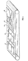
- the dimensions of the conveyor belt 150 are determined in accordance with the possibility of accommodating a plurality of extrudate portions (6), as is also shown in FIG. 4. They can correspond to those of the storage belt 125.
- the control and regulation and monitoring of the position of the individual transport device components is carried out using sensors by the control and control device (PLC), in particular the belt speed of the conveyor belt 150 and the storage belt 125 of the belt scale can be synchronized in order to ensure smooth and seamless transfer to ensure the extrudate portion (s) (b) from the shelf 120 into the transport device 140.
- the feed cylinder 147 of the belt guide frame 151 and the drive 148 of the conveyor belt 150 can be synchronized by the control and control device (PLC) in such a way that the belt guide frame 151 can be retracted with a simultaneous loading movement, i.e. Forward movement of the conveyor belt 150 for exact depositing of the extrudate portion (s) in the compression mold 210 takes place.
- the transport table 143 can simultaneously hold several extrudate portions (b) distributed on its conveyor belt 150, so that different, i.e. extrudate portions (b) having different geometrical dimensions and weights without forming a heap can be introduced specifically into a respective receiving trough (c) - or several areas of such - of the lower compression mold 210.
- the transport device 140 is a conditioning device 160 for tempering / heating the extrudate portion (s) (b) assigned.
- This consists of an insulating hood 161 made of a heat-insulating material with an electronically controlled heatable interior and which is held on a cantilever stand 166 by means of a lifting device 165 and which is arranged in a stationary manner over the transport table 143 located in the receiving position (A).
- a thermostatically controlled heating plate integrated in the insulating hood 161 or an infrared heater is used for temperature control / heating.
- conditioning device 160 also provides an insulating hood 161, which is also held so that it can be moved up and down by motor by means of a suspension above the conveyor belt 150, but which is assigned to each individual transport table 143 and can be moved with it.
- the infeed, ie the up and down movement takes place via the control and monitoring device (PLC), which also takes over / monitors the thermostat control.
- PLC control and monitoring device
- an electronically controlled, motor-driven disposal belt 260 with subsequent extrudate regeneration device 250 is provided.
- PLC control and control device
- a removal device 180 Downstream of the presses 200, 200 'is a removal device 180, also electronically controlled by the control and control device (PLC), for the further transport and / or removal of the pressed plastic parts from the compression mold 210.
- PLC control and control device
- the removal gripper 185 has a gripper head 186 which is rotatable about the feed axis (double arrow f3), and which has a vertically movable (double arrow f1) vacuum suction device 187, by means of which a targeted removal of the finished pressed plastic parts from the top and bottom Press table 215,216 attached mold halves 210 is possible.
- each removal gripper 185 Arranged in the frame 181 below each removal gripper 185 is a removal belt 190.
- This consists of a non-stick coated endless belt 195 with an associated electronically controlled drive 193 in the form of stepper motor-driven rollers, which are accommodated in a belt guide frame 191 which is movably supported in the frame 181 arranged by means of a Feed drive 192 can be moved into and out of the open press 200, 200 '.
- the pressed plastic part can be picked up after ejection from the compression mold 210 and fed to a conveyor roller arrangement 197 for removal or for further transport, for example into a storage facility.
- the recycled plastic to be processed, a mixture of sorted or non-sorted plastics which have been comminuted to flowability, are removed from the storage containers 10, optionally with the addition of a thermoplastic as a binder
- the conveying lines 20 are fed to the respective conveying devices 25 and from there to the mixing device 30, in which mixing takes place according to weight or volume fractions in accordance with a desired plastic composition, possibly regulated by the control and control device (PLC).
- PLC control and control device
- the plastic-granulate mixture to be processed is then fed via a conveyor line 32 to the conveyor device 35, from where the hoppers 60 of the extruder 80 are fed via feed lines.
- the granules are intimately mixed with heating and plasticized with only a brief heat load and, in addition, degassed to the pipe nozzle 100 flanged to the extruder 80.
- the one leaving the heated exit slot 104 of the extrusion tool 100 (tubular nozzle) in the form of a tough plastic mass Extrudate strand (a) is placed on the temperature-controlled storage belt 125 of the belt scale, which can be oscillated and controlled by means of the control and control device (PLC), in a meandering manner.
- the storage base corresponds approximately to the loading area of the plastic part to be molded in the compression mold 210 or a partial area thereof and its desired molding compound distribution, in particular the local thickness of the plastic part.
- control and control device PLC
- PLC control and control device
- the weight of the extrudate strand (a) deposited on the shelf 120 is determined by means of the weighing device 130, so that when a predetermined, predetermined value depending on the finished plastic part has been reached, a signal is sent to the separating device 90 for severing the extrudate. Strand (a) takes place; the weight of the extrudate portion (b) deposited is then measured again.
- the target value is automatically corrected or a temporary target value is set in the control and control device (PLC) and the stored extrudate portion (b) is thereby eliminated from the loading process , in which this is fed to the disposal belt 260, which is followed by the extrudate regeneration device (hot granulate mill) 250, in which cooling and comminution of the plastic extrudate takes place, so that it can in turn be fed to the extrusion process.
- PLC control and control device
- a signal is sent for further transport of the deposit belt 125 and switching on of the conveyor belt 150 of the transport table 143 thereafter located in the receiving position A, whereby the extrudate portion (b) passes through the transport device 140 is received.
- the transport table 143 several extrudate portions (b) are recorded and temporarily stored, the number and arrangement of the extrudate potion (b) on the conveyor belt 150 depending on whether and to what extent one or more loading troughs (c) of one or more press-forming tools 210 of one or more presses 200, 200 'are locally and specifically loaded should.
- Such an arrangement of extrudate portions (b1-b5) made up in various ways is shown, for example, in FIG.
- the insulating hood 161 of the conditioning device 160 is lowered over the conveyor belt 150 of the transport table 143 located in the receiving position A.
- one of the two transport tables 143, 143 ′ provided can be moved alternately into the receiving position A and its respective loading position B in accordance with the arrows e4 and e5.
- the belt guide frame 151 is extended telescopically according to arrow e3 for the locally targeted loading of the loading trough (c) of the opened compression mold 210 with the extrudate portions (b) deposited on the conveyor belt 150 and possibly inclined towards the lower press table 216.
- the finished plastic part is removed from the upper or lower mold half 210 by means of the removal gripper 185 and the vacuum suction device 187 of the removal device 180 and placed on the removal belt 190, where it is transported further to the conveyor roller arrangement 197 for further transport of the finished plastic part or for removal.
- the removal belt 190 can also be retracted telescopically into the opened mold 210, so that plastic parts hanging on the upper mold half can be picked up after being ejected and can be passed on after the conveyor roller arrangement 197 has been retracted.
- a method is specified in which, depending on the number of oscillation strokes of the conveyor belt 125 of the belt scale, the oscillation stroke of an oscillation, as well as the length and width of the outlet slot 104 of the tubular nozzle and possibly also the oscillation of the conveyor belt guide frame 124, a flat, local different thickness distribution having extrudate blank (extrudate portion (b)) can be produced, which can then be pressed in the press mold 210 to the finished plastic part with the greatest possible use of material and without pressing waste.
- extrudate blank is shown, for example, in FIG. 5.
- an extrudate blank formed in this way has is the low-loss temperature distribution over the cross section of the extrudate layer. Due to the flat shape of the extrudate portion (b), lower shear forces occur when pressing flat parts, since there is a smaller flow path for filling the feed trough (c) of the compression mold 210, which almost eliminates residual stresses in the finished plastic part due to " frozen "shear forces. The shorter flow paths also result in reduced pressing forces, which results in further energy savings during the pressing process. With such an extrudate blank or several partial blanks, it is possible to produce flat plastic parts, for example with external dimensions of up to 2600 x 1400 x 20 mm and a weight of about 160kg.
- systems can be put together that have one or more extruders with the associated tray and a transport device, possibly with several transport tables, by means of which a corresponding or even larger number of presses with the shaped extrudate blanks (extrudate portions) ) have it loaded.
Landscapes
- Engineering & Computer Science (AREA)
- Mechanical Engineering (AREA)
- Physics & Mathematics (AREA)
- Thermal Sciences (AREA)
- Manufacturing & Machinery (AREA)
- Robotics (AREA)
- Casting Or Compression Moulding Of Plastics Or The Like (AREA)
- Processing And Handling Of Plastics And Other Materials For Molding In General (AREA)
- Extrusion Moulding Of Plastics Or The Like (AREA)
Applications Claiming Priority (2)
| Application Number | Priority Date | Filing Date | Title |
|---|---|---|---|
| DE4018706 | 1990-06-12 | ||
| DE4018706 | 1990-06-12 |
Publications (2)
| Publication Number | Publication Date |
|---|---|
| EP0461365A1 true EP0461365A1 (fr) | 1991-12-18 |
| EP0461365B1 EP0461365B1 (fr) | 1994-08-10 |
Family
ID=6408213
Family Applications (1)
| Application Number | Title | Priority Date | Filing Date |
|---|---|---|---|
| EP91106302A Expired - Lifetime EP0461365B1 (fr) | 1990-06-12 | 1991-04-19 | Procédé et appareil pour alimenter un moule de compression en matière plastique |
Country Status (3)
| Country | Link |
|---|---|
| EP (1) | EP0461365B1 (fr) |
| AT (1) | ATE109715T1 (fr) |
| DE (1) | DE59102471D1 (fr) |
Cited By (15)
| Publication number | Priority date | Publication date | Assignee | Title |
|---|---|---|---|---|
| EP0480153A3 (en) * | 1990-10-01 | 1992-06-03 | Happich Gmbh Gebr | Method and apparatus for manufacturing a moulded plastics article |
| WO1992022418A1 (fr) * | 1991-06-14 | 1992-12-23 | Eastman Kodak Company | Filieres |
| EP0588362A1 (fr) * | 1992-09-18 | 1994-03-23 | IVECO FIAT S.p.A. | Procédé et système de préparation de charges de matière plastique pour alimenter une presse de moulage |
| FR2700136A1 (fr) * | 1993-01-05 | 1994-07-08 | Moreau Pierre | Procédé et dispositif de recyclage de matières plastiques. |
| WO1995001248A1 (fr) * | 1993-07-02 | 1995-01-12 | Giorgio Ravera | Procede de depot de deux couches superposees d'un materiau thermoplastique sur une matrice de moule |
| DE10021730A1 (de) * | 2000-05-04 | 2001-11-08 | Krupp Werner & Pfleiderer Gmbh | Anlage zur Aufbereitung und Weiterverarbeitung von thermoplastischem Kunststoff |
| WO2005016632A1 (fr) * | 2003-08-05 | 2005-02-24 | Daimlerchrysler Ag | Procede d'assemblage precis en poids de mats impregnes de resine ou de piles de mats impregnes de resine dans la fabrication de composants smc |
| EP1935600A1 (fr) * | 2006-12-20 | 2008-06-25 | Schmidt & Heinzmann GmbH & Co. KG | Dispositif doté d'un dispositif de levage |
| CN107553871A (zh) * | 2017-10-31 | 2018-01-09 | 沈燕 | 一种具有高效生产能力的挤出机 |
| CN110053985A (zh) * | 2019-05-16 | 2019-07-26 | 上海易研机械设备有限公司 | 一种高粘度物料全自动化送料分料系统 |
| CN112339198A (zh) * | 2020-11-02 | 2021-02-09 | 南通超达装备股份有限公司 | 一种150t接触加热烘箱设备 |
| CN114536706A (zh) * | 2022-02-15 | 2022-05-27 | 席梓淇 | 一种eva塑料薄膜挤出机 |
| CN115260734A (zh) * | 2022-09-27 | 2022-11-01 | 广东盟信塑胶实业有限公司 | 一种耐磨抗变形pok塑料棒材及其制备方法 |
| CN117565348A (zh) * | 2024-01-10 | 2024-02-20 | 泉州市锐铭智能科技有限公司 | 一种dmc或bmc复合材料的称重设备 |
| WO2025073491A1 (fr) * | 2023-10-02 | 2025-04-10 | Wimao Oy | Système de fabrication et procédé de fabrication de produits |
Families Citing this family (3)
| Publication number | Priority date | Publication date | Assignee | Title |
|---|---|---|---|---|
| DE10145308C1 (de) * | 2001-09-14 | 2003-03-13 | Daimler Chrysler Ag | Verfahren zum gewichtsgenauen Zusammenstellen von Harzmattenstapeln für die Herstellung von SMC-Teilen |
| DE10152232B4 (de) * | 2001-10-20 | 2005-02-17 | Daimlerchrysler Ag | Verfahren und Vorrichtung zum automatisierten Handhaben von Harzmatten bei der Herstellung von SMC-Teilen |
| DE10219276B4 (de) * | 2002-04-30 | 2006-04-27 | Daimlerchrysler Ag | Mehrachsig manipulierbarer Entnahmegreifer |
Citations (9)
| Publication number | Priority date | Publication date | Assignee | Title |
|---|---|---|---|---|
| US1944464A (en) * | 1928-03-28 | 1934-01-23 | Cutler Hammer Inc | Art of treating plastic molding compositions including a fibrous filler and an organic binder |
| FR1486417A (fr) * | 1966-04-28 | 1967-06-30 | Procédé et moyens de fabrication automatique et en continu d'éléments moulés, notamment pour talons, en partant de matières fibreuses ou autres | |
| US3443277A (en) * | 1964-11-27 | 1969-05-13 | Shell Oil Co | Apparatus for producing a laminate having mechanically interlocking layers |
| US3759653A (en) * | 1971-06-30 | 1973-09-18 | Standard Oil Co | Extrusion die with arched choke bar |
| US4003866A (en) * | 1974-01-22 | 1977-01-18 | Etablissements Paturle S.A. | Construction material and a process for producing the same |
| EP0005961A1 (fr) * | 1978-05-25 | 1979-12-12 | Rehsif S.A. | Procédé et dispositif pour mouler des objets en matière plastique |
| US4304751A (en) * | 1978-05-30 | 1981-12-08 | Allied Corporation | Process for shaping thermoplastic articles |
| US4321027A (en) * | 1979-06-18 | 1982-03-23 | Leesona Corporation | Under the press granulator construction |
| EP0268199A1 (fr) * | 1986-11-19 | 1988-05-25 | BUCHER-GUYER AG Maschinenfabrik | Procédé de fabrication de pièces moulées à base de polymères et équipement pour l'exécution |
-
1991
- 1991-04-19 EP EP91106302A patent/EP0461365B1/fr not_active Expired - Lifetime
- 1991-04-19 AT AT91106302T patent/ATE109715T1/de not_active IP Right Cessation
- 1991-04-19 DE DE59102471T patent/DE59102471D1/de not_active Expired - Fee Related
Patent Citations (9)
| Publication number | Priority date | Publication date | Assignee | Title |
|---|---|---|---|---|
| US1944464A (en) * | 1928-03-28 | 1934-01-23 | Cutler Hammer Inc | Art of treating plastic molding compositions including a fibrous filler and an organic binder |
| US3443277A (en) * | 1964-11-27 | 1969-05-13 | Shell Oil Co | Apparatus for producing a laminate having mechanically interlocking layers |
| FR1486417A (fr) * | 1966-04-28 | 1967-06-30 | Procédé et moyens de fabrication automatique et en continu d'éléments moulés, notamment pour talons, en partant de matières fibreuses ou autres | |
| US3759653A (en) * | 1971-06-30 | 1973-09-18 | Standard Oil Co | Extrusion die with arched choke bar |
| US4003866A (en) * | 1974-01-22 | 1977-01-18 | Etablissements Paturle S.A. | Construction material and a process for producing the same |
| EP0005961A1 (fr) * | 1978-05-25 | 1979-12-12 | Rehsif S.A. | Procédé et dispositif pour mouler des objets en matière plastique |
| US4304751A (en) * | 1978-05-30 | 1981-12-08 | Allied Corporation | Process for shaping thermoplastic articles |
| US4321027A (en) * | 1979-06-18 | 1982-03-23 | Leesona Corporation | Under the press granulator construction |
| EP0268199A1 (fr) * | 1986-11-19 | 1988-05-25 | BUCHER-GUYER AG Maschinenfabrik | Procédé de fabrication de pièces moulées à base de polymères et équipement pour l'exécution |
Non-Patent Citations (3)
| Title |
|---|
| PATENT ABSTRACTS OF JAPAN, Band 10, Nr. 207 (M-500)[2263], 19. Juli 1986; & JP-A-61 47 232 (MEIWA SANGYO K.K.) 07-03-1986 * |
| PATENT ABSTRACTS OF JAPAN, Band 5, Nr. 172 (M-095), 31. Oktober 1981; & JP-A-56 98 120 (YAMAKAWA KOGYO K.K.) 07-08-1981 * |
| PATENT ABSTRACTS OF JAPAN, Band 8, Nr. 191 (M-332)[1628], 4. September 1984; & JP-A-59 81 123 (TOYOTA JIDOSHA K.K.) 10-05-1984 * |
Cited By (23)
| Publication number | Priority date | Publication date | Assignee | Title |
|---|---|---|---|---|
| EP0480153A3 (en) * | 1990-10-01 | 1992-06-03 | Happich Gmbh Gebr | Method and apparatus for manufacturing a moulded plastics article |
| US5326523A (en) * | 1990-10-01 | 1994-07-05 | Gebr. Happich Gmbh | Method for the manufacture of a plastic molded part |
| WO1992022418A1 (fr) * | 1991-06-14 | 1992-12-23 | Eastman Kodak Company | Filieres |
| US5234330A (en) * | 1991-06-14 | 1993-08-10 | Eastman Kodak Company | Dies |
| EP0588362A1 (fr) * | 1992-09-18 | 1994-03-23 | IVECO FIAT S.p.A. | Procédé et système de préparation de charges de matière plastique pour alimenter une presse de moulage |
| US5453228A (en) * | 1992-09-18 | 1995-09-26 | Iveco Fiat S.P.A. | Method and system for preparing plastic material loads for supply to a molding press |
| FR2700136A1 (fr) * | 1993-01-05 | 1994-07-08 | Moreau Pierre | Procédé et dispositif de recyclage de matières plastiques. |
| WO1995001248A1 (fr) * | 1993-07-02 | 1995-01-12 | Giorgio Ravera | Procede de depot de deux couches superposees d'un materiau thermoplastique sur une matrice de moule |
| US7004743B2 (en) | 2000-05-04 | 2006-02-28 | Krupp Werner & Pfleiderer Gmbh & Co. Kg | Installation for the treatment and further processing of thermoplastics and method for the operation thereof |
| DE10021730A1 (de) * | 2000-05-04 | 2001-11-08 | Krupp Werner & Pfleiderer Gmbh | Anlage zur Aufbereitung und Weiterverarbeitung von thermoplastischem Kunststoff |
| WO2005016632A1 (fr) * | 2003-08-05 | 2005-02-24 | Daimlerchrysler Ag | Procede d'assemblage precis en poids de mats impregnes de resine ou de piles de mats impregnes de resine dans la fabrication de composants smc |
| EP1935600A1 (fr) * | 2006-12-20 | 2008-06-25 | Schmidt & Heinzmann GmbH & Co. KG | Dispositif doté d'un dispositif de levage |
| US7891967B2 (en) | 2006-12-20 | 2011-02-22 | Schmidt & Heinzmann Gmbh & Co. Kg | Apparatus having a lifting apparatus |
| CN107553871B (zh) * | 2017-10-31 | 2023-12-08 | 台州豪轩塑胶有限公司 | 一种具有高效生产能力的挤出机 |
| CN107553871A (zh) * | 2017-10-31 | 2018-01-09 | 沈燕 | 一种具有高效生产能力的挤出机 |
| CN110053985A (zh) * | 2019-05-16 | 2019-07-26 | 上海易研机械设备有限公司 | 一种高粘度物料全自动化送料分料系统 |
| CN110053985B (zh) * | 2019-05-16 | 2024-02-02 | 上海易研机械设备有限公司 | 一种高粘度物料全自动化送料分料系统 |
| CN112339198A (zh) * | 2020-11-02 | 2021-02-09 | 南通超达装备股份有限公司 | 一种150t接触加热烘箱设备 |
| CN114536706A (zh) * | 2022-02-15 | 2022-05-27 | 席梓淇 | 一种eva塑料薄膜挤出机 |
| CN115260734A (zh) * | 2022-09-27 | 2022-11-01 | 广东盟信塑胶实业有限公司 | 一种耐磨抗变形pok塑料棒材及其制备方法 |
| WO2025073491A1 (fr) * | 2023-10-02 | 2025-04-10 | Wimao Oy | Système de fabrication et procédé de fabrication de produits |
| CN117565348A (zh) * | 2024-01-10 | 2024-02-20 | 泉州市锐铭智能科技有限公司 | 一种dmc或bmc复合材料的称重设备 |
| CN117565348B (zh) * | 2024-01-10 | 2024-03-22 | 泉州市锐铭智能科技有限公司 | 一种dmc或bmc复合材料的称重设备 |
Also Published As
| Publication number | Publication date |
|---|---|
| DE59102471D1 (de) | 1994-09-15 |
| EP0461365B1 (fr) | 1994-08-10 |
| ATE109715T1 (de) | 1994-08-15 |
Similar Documents
| Publication | Publication Date | Title |
|---|---|---|
| EP0461365B1 (fr) | Procédé et appareil pour alimenter un moule de compression en matière plastique | |
| DE69218491T2 (de) | Verfahren und Vorrichtung zum Formen von Verbundkunststoffmaterial | |
| EP2081758B1 (fr) | Procédé et dispositif de moulage d'ébauches à partir d'une matière malléable | |
| DE2323882C3 (de) | Vorrichtung zum Herstellen eines Schmelzstranges aus Kunststoffabfall | |
| DE69728135T2 (de) | Verfahren und vorrichtung zur herstellung von geschäumtem material | |
| EP0529187B1 (fr) | Appareil pour la production de poudre monodisperse en élastomère | |
| EP1599330B1 (fr) | Procede et dispositif pour fabriquer des corps creux | |
| DE69618459T2 (de) | Verfahren und vorrichtung zum materialzuführen für einen extruder | |
| DE1753819B1 (de) | Vorrichtung zum Herstellen und Stapeln von Formkoerpern aus thermoplastischem Schaumstoff | |
| DE2162229B2 (de) | Verfahren und Vorrichtung zum Einspeisen von Ausgangsstoffen in den Scherspalt von Maschinen zum Herstellen von Filmen, Bahnen, Folien oder Platten aus Kunststoff | |
| DE4307568C2 (de) | Verfahren und Vorrichtung zum Erhitzen und Extrudieren eines Vorformlings | |
| DE3429141C2 (de) | Verfahren zur Herstellung eines Hohlkörpers | |
| DE102019203284A1 (de) | Vorrichtung zur Aufbereitung von thermoplastischem Restpulver | |
| DE29713665U1 (de) | Vorrichtung zum thermischen Formen von Kunststoffolien | |
| DE4024820C2 (de) | Verfahren und Vorrichtung zum Füllen verschiedenartig gestalteter Formen mit thermoplastischem Kunststoff, insbesondere mit stark verunreinigtem Recycling-Kunststoff | |
| EP0895845A1 (fr) | Installation de pressage pour fabriquer des objets moulés en matière plastique | |
| EP1504868B1 (fr) | Procédé et dispositif pour la fabrication des pièces moulées en matières plastiques | |
| DE69903712T2 (de) | Warmformverfahren und vorrichtung | |
| DE4138978C2 (de) | Verfahren und Vorrichtung zur Verarbeitung von unsortiertem thermoplastischem Kunststoffabfall | |
| EP0709177B1 (fr) | Procédé de contrôle d'un appareil de moulage par soufflage | |
| EP2081759B1 (fr) | Procédé et dispositif de moulage à cycles de rotation à haut rendement | |
| DE3925029C1 (fr) | ||
| AT526871B1 (de) | Formgebungsmaschine zum Herstellen von Formteilen | |
| DE102006015851A1 (de) | Extruder zur Plastifizierung von Kunststoff, insbesondere Abfallkunststoff; Verfahren zur Recyclierung von Abfallkunststoff; Anordnung, insbesondere zur Durchführung des Verfahrens | |
| DE2551333A1 (de) | Vorrichtung zur herstellung eines strangfoermigen koerpers aus schaumkunststoff |
Legal Events
| Date | Code | Title | Description |
|---|---|---|---|
| PUAI | Public reference made under article 153(3) epc to a published international application that has entered the european phase |
Free format text: ORIGINAL CODE: 0009012 |
|
| AK | Designated contracting states |
Kind code of ref document: A1 Designated state(s): AT BE CH DE DK ES FR GB GR IT LI LU NL SE |
|
| 17P | Request for examination filed |
Effective date: 19911025 |
|
| 17Q | First examination report despatched |
Effective date: 19930902 |
|
| GRAA | (expected) grant |
Free format text: ORIGINAL CODE: 0009210 |
|
| AK | Designated contracting states |
Kind code of ref document: B1 Designated state(s): AT BE CH DE DK ES FR GB GR IT LI LU NL SE |
|
| PG25 | Lapsed in a contracting state [announced via postgrant information from national office to epo] |
Ref country code: IT Free format text: LAPSE BECAUSE OF FAILURE TO SUBMIT A TRANSLATION OF THE DESCRIPTION OR TO PAY THE FEE WITHIN THE PRE;WARNING: LAPSES OF ITALIAN PATENTS WITH EFFECTIVE DATE BEFORE 2007 MAY HAVE OCCURRED AT ANY TIME BEFORE 2007. THE CORRECT EFFECTIVE DATE MAY BE DIFFERENT FROM THE ONE RECORDED.SCRIBED TIME-LIMIT Effective date: 19940810 Ref country code: DK Effective date: 19940810 Ref country code: NL Effective date: 19940810 Ref country code: BE Effective date: 19940810 Ref country code: GB Effective date: 19940810 Ref country code: FR Effective date: 19940810 Ref country code: ES Free format text: THE PATENT HAS BEEN ANNULLED BY A DECISION OF A NATIONAL AUTHORITY Effective date: 19940810 Ref country code: GR Free format text: LAPSE BECAUSE OF FAILURE TO SUBMIT A TRANSLATION OF THE DESCRIPTION OR TO PAY THE FEE WITHIN THE PRESCRIBED TIME-LIMIT Effective date: 19940810 |
|
| REF | Corresponds to: |
Ref document number: 109715 Country of ref document: AT Date of ref document: 19940815 Kind code of ref document: T |
|
| REF | Corresponds to: |
Ref document number: 59102471 Country of ref document: DE Date of ref document: 19940915 |
|
| PG25 | Lapsed in a contracting state [announced via postgrant information from national office to epo] |
Ref country code: SE Effective date: 19941110 |
|
| EN | Fr: translation not filed | ||
| NLV1 | Nl: lapsed or annulled due to failure to fulfill the requirements of art. 29p and 29m of the patents act | ||
| GBV | Gb: ep patent (uk) treated as always having been void in accordance with gb section 77(7)/1977 [no translation filed] |
Effective date: 19940810 |
|
| PG25 | Lapsed in a contracting state [announced via postgrant information from national office to epo] |
Ref country code: LU Free format text: LAPSE BECAUSE OF NON-PAYMENT OF DUE FEES Effective date: 19950430 |
|
| PGFP | Annual fee paid to national office [announced via postgrant information from national office to epo] |
Ref country code: AT Payment date: 19950523 Year of fee payment: 5 |
|
| PLBE | No opposition filed within time limit |
Free format text: ORIGINAL CODE: 0009261 |
|
| STAA | Information on the status of an ep patent application or granted ep patent |
Free format text: STATUS: NO OPPOSITION FILED WITHIN TIME LIMIT |
|
| PGFP | Annual fee paid to national office [announced via postgrant information from national office to epo] |
Ref country code: CH Payment date: 19950621 Year of fee payment: 5 |
|
| 26N | No opposition filed | ||
| PG25 | Lapsed in a contracting state [announced via postgrant information from national office to epo] |
Ref country code: DE Effective date: 19960103 |
|
| PG25 | Lapsed in a contracting state [announced via postgrant information from national office to epo] |
Ref country code: AT Effective date: 19960419 |
|
| PG25 | Lapsed in a contracting state [announced via postgrant information from national office to epo] |
Ref country code: CH Effective date: 19960430 Ref country code: LI Effective date: 19960430 |
|
| REG | Reference to a national code |
Ref country code: CH Ref legal event code: PL |