EP0461383A2 - Récipient à échantillons pour la décomposition ou l'analyse d'un échantillon - Google Patents
Récipient à échantillons pour la décomposition ou l'analyse d'un échantillon Download PDFInfo
- Publication number
- EP0461383A2 EP0461383A2 EP91107194A EP91107194A EP0461383A2 EP 0461383 A2 EP0461383 A2 EP 0461383A2 EP 91107194 A EP91107194 A EP 91107194A EP 91107194 A EP91107194 A EP 91107194A EP 0461383 A2 EP0461383 A2 EP 0461383A2
- Authority
- EP
- European Patent Office
- Prior art keywords
- sample container
- valve
- pressure piece
- container according
- sample
- Prior art date
- Legal status (The legal status is an assumption and is not a legal conclusion. Google has not performed a legal analysis and makes no representation as to the accuracy of the status listed.)
- Granted
Links
Images

Classifications
-
- G—PHYSICS
- G01—MEASURING; TESTING
- G01N—INVESTIGATING OR ANALYSING MATERIALS BY DETERMINING THEIR CHEMICAL OR PHYSICAL PROPERTIES
- G01N1/00—Sampling; Preparing specimens for investigation
- G01N1/28—Preparing specimens for investigation including physical details of (bio-)chemical methods covered elsewhere, e.g. G01N33/50, C12Q
-
- B—PERFORMING OPERATIONS; TRANSPORTING
- B01—PHYSICAL OR CHEMICAL PROCESSES OR APPARATUS IN GENERAL
- B01J—CHEMICAL OR PHYSICAL PROCESSES, e.g. CATALYSIS OR COLLOID CHEMISTRY; THEIR RELEVANT APPARATUS
- B01J19/00—Chemical, physical or physico-chemical processes in general; Their relevant apparatus
- B01J19/08—Processes employing the direct application of electric or wave energy, or particle radiation; Apparatus therefor
- B01J19/12—Processes employing the direct application of electric or wave energy, or particle radiation; Apparatus therefor employing electromagnetic waves
- B01J19/122—Incoherent waves
- B01J19/126—Microwaves
-
- B—PERFORMING OPERATIONS; TRANSPORTING
- B01—PHYSICAL OR CHEMICAL PROCESSES OR APPARATUS IN GENERAL
- B01L—CHEMICAL OR PHYSICAL LABORATORY APPARATUS FOR GENERAL USE
- B01L3/00—Containers or dishes for laboratory use, e.g. laboratory glassware; Droppers
- B01L3/04—Crucibles
-
- H—ELECTRICITY
- H05—ELECTRIC TECHNIQUES NOT OTHERWISE PROVIDED FOR
- H05B—ELECTRIC HEATING; ELECTRIC LIGHT SOURCES NOT OTHERWISE PROVIDED FOR; CIRCUIT ARRANGEMENTS FOR ELECTRIC LIGHT SOURCES, IN GENERAL
- H05B6/00—Heating by electric, magnetic or electromagnetic fields
- H05B6/64—Heating using microwaves
- H05B6/6408—Supports or covers specially adapted for use in microwave heating apparatus
-
- B—PERFORMING OPERATIONS; TRANSPORTING
- B01—PHYSICAL OR CHEMICAL PROCESSES OR APPARATUS IN GENERAL
- B01J—CHEMICAL OR PHYSICAL PROCESSES, e.g. CATALYSIS OR COLLOID CHEMISTRY; THEIR RELEVANT APPARATUS
- B01J2219/00—Chemical, physical or physico-chemical processes in general; Their relevant apparatus
- B01J2219/08—Processes employing the direct application of electric or wave energy, or particle radiation; Apparatus therefor
- B01J2219/12—Processes employing electromagnetic waves
- B01J2219/1203—Incoherent waves
- B01J2219/1206—Microwaves
- B01J2219/1209—Features relating to the reactor or vessel
-
- B—PERFORMING OPERATIONS; TRANSPORTING
- B01—PHYSICAL OR CHEMICAL PROCESSES OR APPARATUS IN GENERAL
- B01J—CHEMICAL OR PHYSICAL PROCESSES, e.g. CATALYSIS OR COLLOID CHEMISTRY; THEIR RELEVANT APPARATUS
- B01J2219/00—Chemical, physical or physico-chemical processes in general; Their relevant apparatus
- B01J2219/08—Processes employing the direct application of electric or wave energy, or particle radiation; Apparatus therefor
- B01J2219/12—Processes employing electromagnetic waves
- B01J2219/1203—Incoherent waves
- B01J2219/1206—Microwaves
- B01J2219/1209—Features relating to the reactor or vessel
- B01J2219/1212—Arrangements of the reactor or the reactors
- B01J2219/1215—Single reactor
-
- B—PERFORMING OPERATIONS; TRANSPORTING
- B01—PHYSICAL OR CHEMICAL PROCESSES OR APPARATUS IN GENERAL
- B01J—CHEMICAL OR PHYSICAL PROCESSES, e.g. CATALYSIS OR COLLOID CHEMISTRY; THEIR RELEVANT APPARATUS
- B01J2219/00—Chemical, physical or physico-chemical processes in general; Their relevant apparatus
- B01J2219/08—Processes employing the direct application of electric or wave energy, or particle radiation; Apparatus therefor
- B01J2219/12—Processes employing electromagnetic waves
- B01J2219/1203—Incoherent waves
- B01J2219/1206—Microwaves
- B01J2219/1209—Features relating to the reactor or vessel
- B01J2219/1212—Arrangements of the reactor or the reactors
- B01J2219/1218—Multiple reactors
-
- G—PHYSICS
- G01—MEASURING; TESTING
- G01N—INVESTIGATING OR ANALYSING MATERIALS BY DETERMINING THEIR CHEMICAL OR PHYSICAL PROPERTIES
- G01N1/00—Sampling; Preparing specimens for investigation
- G01N1/28—Preparing specimens for investigation including physical details of (bio-)chemical methods covered elsewhere, e.g. G01N33/50, C12Q
- G01N1/44—Sample treatment involving radiation, e.g. heat
Definitions
- the invention relates to a sample container according to the preamble of claims 1 and 7 respectively
- sample container In such a sample container, one or more materials are chemically treated at the same time for the digestion or analysis of the materials, it being possible to add heat to force this chemical treatment.
- a sample material to be examined in the sample container can be, for example, sewage sludge which is to be digested with highly aggressive acids.
- the digestion process i.e. To accelerate the chemical process, it is customary to heat the sample material to which acids or other disintegrating agents have been added, the sample container with the sample material and the disintegrating agent being heated in a heating device, preferably being exposed to microwave radiation in a microwave oven.
- a high overpressure can arise in the sample container due to the heating.
- a valve is provided in an outlet opening which opens automatically when a predetermined internal pressure is exceeded.
- DE-A-38 39 901 describes a sample container of the type specified at the outset, which has a lower container part with a lid which, as a cup-shaped cylindrical cover, can be screwed onto the cup-shaped cylindrical lower container part in the upside-down position.
- the valve is integrated in a valve body which can be screwed onto a connection piece which is arranged centrally on the cover and contains the outlet opening.
- the valve is located in an outlet channel passing through the valve body and comprises a conical valve seat against which a valve member with a corresponding conical valve member head can be pretensioned from above with such a bias that the valve member exposed to the internal pressure of the sample container is at a predetermined internal pressure in the container from the valve seat lifts upwards and exposes the outlet opening.
- the valve member is vertically displaceably mounted in a pin which can be screwed from above into a recess in the valve body which is open at the top.
- the pretension of the valve member is formed by a particularly disc-shaped pressure piece made of elastic material, preferably of silicone, which is arranged between the valve member and the pin.
- the pin can be started with a screw its upper end arranged in the sense of a pressure screw so far into the valve body that the elastic pressure piece is compressed and thus the biasing force is generated.
- the screw-in depth of the pin and thus the pretensioning force can be determined by means of marks attached to the valve body and / or to the rotary member.
- the sample material in the sample container is preferably heated in a microwave oven, it being possible for several sample containers to be heated simultaneously.
- a rotating stand must be provided in the microwave oven on which the sample containers can be rotated about a vertical axis.
- the sample container or containers require a chemically inert and microwave-transparent material.
- a temperature-resistant and chemically inert plastic is very suitable for this.
- the valve member is formed by the cover itself, a flat aluminum support disk being arranged on the cover.
- a holder which overlaps the cover forming the valve element in FIG holds its closed position.
- a holder is provided on the underside of the sample container with a base plate and on the upper side with a holding plate, wherein a pressure screw can be screwed into the holding plate coaxially with the sample container, the lower end of which presses vertically against the support disk and thus holds the valve in its closed position.
- the invention has for its object to improve the functional stability in a sample container of the type specified.
- the pressure piece is shaped like a plate spring. Because of this configuration, the pressure piece is mainly subjected to bending and not to compression. In this way, both for a pressure piece of a sample container and for several pressure pieces several sample containers achieve essentially uniform parameters of elasticity, so that the pressure exerted by the pressure piece on the valve can be controlled and determined more easily. It is thus possible in a simpler manner to produce pressure pieces with essentially uniform elasticity parameters. Way is achieved.
- sample container according to the invention according to claim 1 is that on the one hand a small cross-sectional size for the pressure piece and on the other hand larger spring forces and also a greater spring travel of the pressure piece can be achieved in a simpler manner. The latter is important for handling reasons when tightening the pressure screw of the holder against the lid. If a larger spring travel is available, the pressure differences achieved in each case have less influence on the opening pressure, because less closing force differences can be achieved. Larger differences in closing force would lead to different opening pressures, which is undesirable.
- a spring action of the pressure piece with a spring characteristic without a slope is particularly advantageous. Such a spring action is comparable to a weight that always exerts an equally large force regardless of the distance traveled.
- the valve is stabilized due to the dimensionally stable intermediate part.
- the manufacturer is free to choose the material for the lid, so that he can also choose a softer and / or more heat-resistant or chemically inert and less dimensionally stable material.
- a PTFE derivative or Teflon which is relatively soft, especially at higher temperatures, is particularly suitable as the material for the lid. This is irrelevant because the shape stability of the intermediate part replaces the shape stability of the cover. The dimensional stability is thus retained, the elasticity of the pressure piece having an essentially unadulterated effect, so that for this reason the valve will open in a targeted manner at a certain and preferably always the same opening pressure.
- the pressure piece preferably consists of a hard or tough-elastic plastic, in particular HTC (high temperature compound) plastic
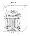
- the heater 1 is a microwave oven with a housing 3 enclosing a boiler room 2 with a door 4 on its front side.
- the supporting part 5 preferably in the form of a round disk 6, can be rotated about a vertical axis of rotation 7.
- six stands 8 are provided for six sample containers 9, two of which are shown visibly opposite one another.
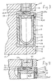
- the sample containers 9 are preferably configured identically to one another and each consist of a cup-shaped housing 11 with a horizontal cross section with a horizontal housing base 12 and a cylindrical, vertically extending housing wall 13 with an edge flange 13a.
- the round one Lid 14 closable housing opening 15 is limited by the upper inner edge of the housing wall 13.
- the sample container 9 is assigned a valve 16 in its upper region, which automatically opens when a certain internal pressure in the sample container 9 is exceeded, which is exposed to heat when a sample material contained therein is broken open, so that the internal pressure can escape to the outside and decrease. This prevents the internal pressure from exceeding a predetermined value and the sample container 9 from being overloaded or from exploding.
- the valve member of the valve 16 is the cover 14 itself.
- the valve seat 17 of the valve 16 is formed on the upper edge of the cylindrical housing wall 13 and is formed by the upper concentric, radial annular edge surface 18 of the cylindrical housing wall 13 and its edge flange 13a.
- a correspondingly shaped radial, annular sealing surface 19 has the cover 14 on the underside on its outer peripheral edge.
- the diameter of the disk-shaped cover 14 corresponds approximately to the outer diameter of the housing 11, whereby it can be dimensioned slightly larger.
- the cover 14 also has a centering projection 14a on the underside which surrounds the housing 11 and whose horizontal lower surface is designated by 21. At the top of the cover 14 there is a concentric round recess 22 with a radial and thus flat base area 23.
- the cover 14 is assigned a predetermined breaking point 24, which is preferably formed by a weakening of the disk-shaped cover 14, in particular in the form of a Ring groove or a central blind hole 25, which are preferably arranged on the top in the cover 14.
- the cover 14 is assigned a disk-shaped intermediate part 27 on the upper side, which is inserted into the recess 22 in a substantially closing manner, so that its radial lower surface rests on the base 23 of the recess 22 and its peripheral surface preferably also bears against the hollow cylindrical inner wall of the recess 22.
- the round intermediate part 27 has a diameter which projects beyond the inner edge of the edge surface 18 and can approximately correspond to the outer diameter of the housing wall 13 or the edge flange 13a. 11 corresponds, but its diameter can also be larger than the housing 11.
- At the top of the intermediate part 27 there is concentrically a round recess 28 with a radial and thus flat base surface 29.
- Each sample container 9 is assigned a disk-shaped, elastic pressure piece 31, which is used for the functional operation of the sample container 9 on the cover 14 in the recess 28. Due to its elasticity, the pressure piece 31 is able to generate a defined preload for the valve 16. The pressure piece 31 is located outside the sample container 9 and thus in the cold, air-flushed area.
- the pressure piece 31 can be a disk made of elastic solid material or a plate-spring-shaped body such as a particularly dome-shaped hollow body and preferably an annular or closed plate spring.
- the plate-spring-shaped twill is arranged in a downward divergent position, its outer circumferential edge being seated in the recess 28 with play or having a circumferential play therein.
- the plate spring 31 is shaped like a truncated cone with a radial flat head surface 31a.
- the lower edge is preferably also provided with a radial foot ring surface 31b.
- the tip of the cavity of the plate spring 31 can be tapered or flattened.
- the wall of the flanks is preferably of the same thickness, see thickness d.
- the plate spring 31 can have a central hole and thus be annular or be a closed component.
- the plate spring 31 has a spring travel of up to about 2 to 3 mm, on which its biasing force is or remains essentially the same.
- the sample container 9 consists of a microwave-transparent and chemically inert material, in particular plastic.
- a temperature-resistant plastic preferably a polytetrafluoroethylene derivative, which is relatively soft (PTFE, Teflon, TFA, PFA), in particular at higher temperatures, is suitable for the housing 11 and the cover 14.
- the pressure piece 31 consists of a hard or tough-elastic plastic, preferably an HTC (high temperature compound) plastic, such as polyetermide (PEI) or polyether ether ketone (PEEK). It can also be made of an elastomeric material such as Silicon and Viton exist.
- PEI polyetermide
- PEEK polyether ether ketone
- the intermediate part 27 consists of a hard plastic, which gives the intermediate part 27 great resistance to deformation and bending, in particular at different temperatures, and thus a high pressure stability.
- the pressure stability or bending strength of the intermediate part 27 is greater than the pressure stability of the plate spring. This also applies to a disc-shaped pressure piece made of elastic solid material.
- the pot-shaped housing 11 is formed by a tube piece, preferably surrounding the cylindrical housing wall 13 over its entire height Surround protective jacket 35, with which it is preferably firmly connected, for example by press fitting or gluing.
- the protective jacket is preferably made of highly tear-resistant plastic, such as polyetermide (PEI), polyether ether ketone (PEEK), for example from the same material described above, from which the plate spring 31 is made.
- the protective jacket 35 can have a hole through which the temperature on the outer surface of the housing 11 can be measured by means of a temperature sensor for the purpose of controlling the rotary drive of the support part 5, the heating energy and / or the heating time of the microwave oven.
- the support part 5 has a support part for each sample container 9, which overlaps the pressure piece 31 of the associated sample container 9 in the position of the sample container 9 set on or in the support part 5, the sample container with such a clamping force between the support part and the standing surface 36 is clamped on the supporting part 5, which, when a certain internal pressure in the sample container 9 is exceeded, lifts the cover 14 against the clamping force of the pressure piece 31 and thus opens the valve 16.
- the support part generally designated 37, is coaxially associated with each stand 8, a tensioning device 38 with which the biasing force of the valve 16 can be brought about, which is predetermined by the tensioning force of the elastic pressure piece 31.
- the support part 37 is a preferably round upper flange or disk 39 of the supporting part 5, which is connected to the lower disk 6 by a vertical shaft 40, for example in one piece or by screws (not shown).
- a set screw 41 with an external thread is screwed coaxially above each stand 8 into a corresponding vertical threaded hole 42 in the upper disks 39.
- the lower end of the adjusting screw 41 protrudes slightly downward from the lower surface of the upper disk 39.
- the set screw 41 has a tool engagement element, for example an internal or external hexagon.
- the set screw 41 In the operating position, the set screw 41 is located coaxially above the cover 14 and above the pressure piece 31. By tightening the set screw 41, the pressure piece 31 and the cover 14 are pressed down against the housing 11, as a result of which a certain pressure is achieved.
- the arrangement can be such that the set screw 41 is screwed against a stop in the tightened position, which can be achieved by screwing a screw head against the upper disk 39.
- a plurality of pressure pieces 31 can be provided for each sample container 9 in a corresponding number, the elasticity or clamping force of which is correspondingly different and adapted to the respectively desired opening pressure.
- a recess 45 is arranged at each stand 8, which is preferably open radially outward, so that the associated sample container 9 can be inserted from the side comfortably.
- the recess 45 is shaped at least in the inner region, or adapted to the cross-sectional shape of the sample container 9, that it is centered in the correct position.
- the supporting part 5 is assigned a protective housing 46, which is indicated and which can preferably be placed over the supporting part 5 from above.
- a protective housing 46 Preferably, on the circumferential wall of the lower disk 6 there is a step 47 tapering upwards with an attachment edge onto which the optionally bell-shaped protective housing 46 can be placed.
- the protective housing 46 is preferably made of transparent material such as glass or plastic, so that the sample container 9 and, if appropriate, their reaction when heated are visible from the outside.
- the design of the supporting part 5 or of the disks 6 and / or 39 can also be such that the respective support part or at least one of the two disks 6, 39 bends slightly elastically under the opening pressure which is effective in its operation from the associated sample container 9 or give way elastically.
- these parts fulfill a secondary opening function for the valve 16, so that the valve 16 is opened reliably when an internal pressure which is above normal is exceeded.
- the support member 5 or the discs 6.39 are also made of plastic.
- the above-described additional opening function is favored in that the reaction to heat is transferred to the flanges 6, 39 and the plastic material is softened and the strength is reduced, so that one or the other disk 6.39 can bend.
- the temperature resistance of this plastic is preferably lower than that of the protective jacket 35 and / or the pressure piece 31, so that this plastic melts rather.
- the bottom 12 of the housing 11 is thicker than its wall 13 for the purpose of thermal insulation.
- the adjusting screw 41 is preferably also made of plastic, namely from a hard plastic, in order to prevent the disk spring from being pressed into the adjusting screw 41.
- the lid pressure increases first because the container plastic expands. If the internal pressure generates a force directed from the inside onto the cover 14 that exceeds the clamping force of the pressure piece 31, then the opening pressure is reached and the cover 14 rises slightly in parallel, the internal pressure escaping between the surfaces 18, 19 of the sample container 9 .
- an inner container 51 preferably made of quartz, is provided as an additional component, which can be inserted into the housing 11 from above with play and has a flange shoulder 52 on its edge , with which it rests in its inserted position on the edge surface 18 of the housing 11.
- the cover 14 has an edge or flange shoulder 52 of the inner container 51 receiving the annular groove 53, so that due to a centering shoulder of the cover 14 encompassing the inner container 51, the centering is maintained and the cover 14 continues with its sealing surface 19 on the Edge surface 18 of the housing 11 rests, whereby the sealing of the sample container 9 is ensured.
- the base 53a of the annular groove fulfills the function of a sealing surface for the inner container in that it rests tightly on it.
- the bottom of the inner container 51 is preferably rounded in a hemispherical manner and is thus released from bending forces caused by the internal pressure.
- the inner container 51 can thus be made of fragile material, in particular quartz. Quartz is particularly suitable because it is chemically inert and transparent to microwaves and also leads to considerable thermal insulation.
- the plate spring forming the pressure piece 31 generates a closing force of approximately 10,000 N, 1000 Kp, the valve 16 opening at an internal pressure of approximately 110 bar.
- the user wants to use a lower internal pressure of e.g. 60 bar and a corresponding lower temperature, then he uses the sample container 9 without inner container 51st
- the joint formed by the edge surface 18 of the housing 11 and the sealing surface 19 of the cover 14 is covered radially outwards by a protective ring 56, which extends through the circumferential direction Fits tightly or with little movement.
- the protective ring 56 has a radial through hole 57, the central axis of which is approximately at the level of the joint.
- a plurality of holes 57 can also be provided, which are arranged distributed over the circumference.
- the protective ring 56 is a separate component which can be pushed with play from above over the cover 14 and over the edge flange 13a, the protective ring 56 resting on the upper edge surface of the protective jacket 35, which is somewhat larger in diameter than the cover 14 and the edge flange 13a, which are of the same size in the present case.
- the protective ring 56 also consists of a microwave-transparent and chemically inert plastic, preferably of the same plastic from which the cover 14 and the housing 11 are made (PTFE derivatives).
- the protective ring 56 on its upper edge with an inner flange so that it rests on the upper side of the cover 14. With such a configuration, there is no need for the protective ring 56 to rest on the protective jacket 35. In this case, the protective jacket can therefore be made smaller or thinner will. It is also possible within the scope of the invention to form the protective ring 56 in one piece on the outer edge of the edge flange 13a of the housing 11 or on the upper edge of the protective jacket 35, it protruding upward from these parts. It is also possible to form the protective ring 56 on the circumference of the cover 14 so that it protrudes downward from the latter.
Landscapes
- Chemical & Material Sciences (AREA)
- Physics & Mathematics (AREA)
- Health & Medical Sciences (AREA)
- Electromagnetism (AREA)
- General Health & Medical Sciences (AREA)
- Chemical Kinetics & Catalysis (AREA)
- Biochemistry (AREA)
- Analytical Chemistry (AREA)
- Life Sciences & Earth Sciences (AREA)
- Clinical Laboratory Science (AREA)
- General Physics & Mathematics (AREA)
- Immunology (AREA)
- Pathology (AREA)
- Toxicology (AREA)
- Organic Chemistry (AREA)
- Sampling And Sample Adjustment (AREA)
- Devices For Use In Laboratory Experiments (AREA)
- Investigating Or Analyzing Non-Biological Materials By The Use Of Chemical Means (AREA)
Applications Claiming Priority (2)
| Application Number | Priority Date | Filing Date | Title |
|---|---|---|---|
| DE4018955 | 1990-06-13 | ||
| DE4018955A DE4018955A1 (de) | 1990-06-13 | 1990-06-13 | Probenbehaelter zum aufschliessen bzw. analysieren von probenmaterial |
Publications (4)
| Publication Number | Publication Date |
|---|---|
| EP0461383A2 true EP0461383A2 (fr) | 1991-12-18 |
| EP0461383A3 EP0461383A3 (en) | 1992-03-11 |
| EP0461383B1 EP0461383B1 (fr) | 1994-08-03 |
| EP0461383B2 EP0461383B2 (fr) | 2001-05-02 |
Family
ID=6408356
Family Applications (1)
| Application Number | Title | Priority Date | Filing Date |
|---|---|---|---|
| EP91107194A Expired - Lifetime EP0461383B2 (fr) | 1990-06-13 | 1991-05-03 | Récipient à échantillons pour la décomposition ou l'analyse d'un échantillon |
Country Status (4)
| Country | Link |
|---|---|
| US (2) | US5270010A (fr) |
| EP (1) | EP0461383B2 (fr) |
| AT (1) | ATE109377T1 (fr) |
| DE (2) | DE4018955A1 (fr) |
Cited By (4)
| Publication number | Priority date | Publication date | Assignee | Title |
|---|---|---|---|---|
| FR2674146A1 (fr) * | 1991-03-18 | 1992-09-25 | Knapp Gunter | Dispositif pour chauffer des substances en creant des pressions elevees dans un champ de micro-ondes. |
| DE19947404A1 (de) * | 1999-10-01 | 2001-05-10 | Norman Loftfield | Reaktionsgefäß für den Druckaufschluß von Probenmaterial |
| BE1014233A3 (fr) * | 1997-03-18 | 2003-07-01 | Basf Ag | Systeme d'echantillonnage pour gaz liquefies et liquides. |
| DE19700530B4 (de) * | 1997-01-09 | 2007-09-06 | Perkin Elmer Bodenseewerk Zweigniederlassung Der Berthold Gmbh & Co. Kg | Vorrichtung zur Durchführung naßchemischer Reaktionen unter Druck |
Families Citing this family (26)
| Publication number | Priority date | Publication date | Assignee | Title |
|---|---|---|---|---|
| DE4018955A1 (de) * | 1990-06-13 | 1991-12-19 | Werner Lautenschlaeger | Probenbehaelter zum aufschliessen bzw. analysieren von probenmaterial |
| DE4223116A1 (de) * | 1992-04-30 | 1993-11-04 | Mikrowellen Labor Systeme | Vorrichtung zur verdampfungsbehandlung von vorzugsweise fluessigen stoffen, insbesondere reagenzstoffen, oder zum aufbereiten oder analysieren von probenmaterial |
| DE4413426C2 (de) * | 1994-04-18 | 2002-05-08 | Anton Paar Gmbh Graz | Vorrichtung zur Druck- und Temperaturmessung in mindestens einem mit einem Deckel verschlossenen, druckdichten Aufschlußgefäß |
| DE4417665A1 (de) * | 1994-05-20 | 1995-11-30 | Testo Gmbh & Co | Meßanordnung zur Untersuchung gasförmiger Medien |
| DE19543401A1 (de) * | 1995-11-21 | 1997-05-22 | Mikrowellen Systeme Mws Gmbh | Vorrichtung zur Wärmebehandlung einer Probe durch die Bestrahlung mit Mikrowellen |
| US5731210A (en) * | 1995-12-13 | 1998-03-24 | R. J. Reynolds Tobacco Company | Environmental evaporation chamber and method of using same |
| DE19700499B4 (de) * | 1996-12-23 | 2005-06-02 | Mikrowellen-Systeme Mws Gmbh | Vorrichtung zum Behandeln chemischer Substanzen durch Erhitzen |
| KR20010023070A (ko) | 1997-08-20 | 2001-03-26 | 더 유니버시티 오브 마이애미 | 고품질의 연속적인 재료 처리, 조직 고정-탈수-지방제거-함침 방법 |
| WO1999054034A1 (fr) * | 1998-04-20 | 1999-10-28 | Cem Corporation | Recipient souple et chassis pour traitements chimiques assistes par hyperfrequences |
| US6534140B2 (en) * | 1999-03-01 | 2003-03-18 | Cem Limited, L.L.C. | Pressure vessel with composite sleeve |
| US6287526B1 (en) * | 1999-06-01 | 2001-09-11 | Cem Corporation | Sealing closure for high pressure vessels in microwave assisted chemistry |
| DE10063925A1 (de) * | 2000-12-20 | 2002-07-11 | Webasto Thermosysteme Gmbh | Heizgerät für ein Fahrzeug mit einem Überhitzungssensor |
| US7285423B2 (en) * | 2000-12-22 | 2007-10-23 | Biotage Ab | Penetrable pressure proof sealing for a container |
| US6893613B2 (en) * | 2002-01-25 | 2005-05-17 | Bristol-Myers Squibb Company | Parallel chemistry reactor with interchangeable vessel carrying inserts |
| DE10227836B4 (de) * | 2002-06-21 | 2006-02-09 | Mikrowellen-Systeme Mws Gmbh | Verfahren, Verwendung des Verfahrens sowie Verwendung eines Mikrowellenheizgeräts zum Mischen und zur Auslösung von chemischen Reaktionen von Feststoffgemischen oder Suspensionen in einem Mikrowellenfeld |
| US7144739B2 (en) * | 2002-11-26 | 2006-12-05 | Cem Corporation | Pressure measurement and relief for microwave-assisted chemical reactions |
| DE10258104B4 (de) * | 2002-12-11 | 2005-11-03 | Leica Mikrosysteme Gmbh | Präparathalter mit Entnahmehilfe für die Mikrotomie und die AFM-Mikroskopie |
| ATE442576T1 (de) * | 2003-10-24 | 2009-09-15 | Univ Miami | Vereinfachte gewebeverarbeitung |
| US7829040B2 (en) * | 2009-03-05 | 2010-11-09 | Cem Corporation | High temperature high pressure vessel for microwave assisted chemistry |
| EP2972219B1 (fr) | 2013-03-15 | 2022-01-19 | Abbott Laboratories | Gestionnaire de réactif automatisé de système analyseur de diagnostic |
| US9632103B2 (en) | 2013-03-15 | 2017-04-25 | Abbott Laboraties | Linear track diagnostic analyzer |
| WO2014144870A2 (fr) | 2013-03-15 | 2014-09-18 | Abbott Laboratories | Système de blocage de lumière pour un analyseur de diagnostic |
| BR112018008629B1 (pt) * | 2015-11-04 | 2020-11-17 | Nitto Denko Corporation | aparelho para ensaio de um biofluido, aparelho para contenção e dispensa de amostras de biofluido e sistema para dispensa e ensaio de biofluido |
| CN105752470B (zh) * | 2016-04-26 | 2018-08-07 | 湖南三德科技股份有限公司 | 一种智能化样品收集装置 |
| US10065168B2 (en) | 2016-05-02 | 2018-09-04 | Cem Corporation | High temperature pressure digestion vessel system with dual action seal |
| USD806260S1 (en) * | 2016-07-12 | 2017-12-26 | Siemens Healthcare Diagnostics Inc. | Sample carrier |
Family Cites Families (19)
| Publication number | Priority date | Publication date | Assignee | Title |
|---|---|---|---|---|
| DE1251116B (fr) * | 1961-03-11 | 1900-01-01 | ||
| US3265296A (en) * | 1964-03-06 | 1966-08-09 | Internat Equipment Company | Plastic centrifuge bottles and caps therefor |
| US3459369A (en) * | 1965-09-16 | 1969-08-05 | Beckman Instruments Inc | Centrifuge test tube cap |
| US4079854A (en) * | 1976-08-09 | 1978-03-21 | Continental Disc Corporation | Rupture disc pressure relief device |
| CA1080435A (fr) * | 1977-04-26 | 1980-07-01 | Her Majesty The Queen In Right Of Canada As Represented By The Minister Of National Defence Of Her Majesty's Canadian Government | Reacteur sous pression a haute precision |
| US4168012A (en) * | 1978-05-30 | 1979-09-18 | Outboard Marine Corporation | Fuel cap assembly |
| US4342419A (en) * | 1980-10-31 | 1982-08-03 | Beckman Instruments, Inc. | Safety cover for centrifuge bucket |
| US4689306A (en) * | 1982-03-19 | 1987-08-25 | Institut Biokhimii I Fiziologii Mikroorganizmov Akademii Nauk Sssr | Device for sterile sampling from a fermenter |
| DE3681319D1 (de) * | 1985-04-11 | 1991-10-17 | Cem Corp | Selbstregulierendes ventilin einem mikrowellen- und behaeltersystem. |
| US4752445A (en) * | 1985-08-20 | 1988-06-21 | American Sterilizer Company | Bi-directional sealing method to control fluid flow between an air inlet and a pressure chamber |
| US4690670A (en) * | 1986-01-10 | 1987-09-01 | Nielsen Steven T | Centrifuge tube having reusable seal |
| DE3620381A1 (de) * | 1986-06-18 | 1988-01-14 | Schultz Wolfgang | Druckaufschlussapparatur fuer die analytische chemie |
| US4882128A (en) * | 1987-07-31 | 1989-11-21 | Parr Instrument Company | Pressure and temperature reaction vessel, method, and apparatus |
| JP2611785B2 (ja) * | 1987-10-24 | 1997-05-21 | 豊田合成株式会社 | フユーエルキヤツプ |
| DE8817046U1 (de) * | 1988-06-01 | 1992-06-25 | Jasper B.V., Den Haag/s'Gravenhage | Probenbehälter zum analytischen Aufschließen von Probenmaterial |
| DE3839901A1 (de) * | 1988-11-25 | 1990-05-31 | Werner Lautenschlaeger | Probenbehaelter zum aufschliessen von probenmaterial |
| FR2642218B1 (fr) * | 1989-01-24 | 1992-07-24 | Commissariat Energie Atomique | Appareil de dissolution sous pression |
| US4993602A (en) * | 1989-06-07 | 1991-02-19 | Prd, Inc. | Pressure relief device for a pressurized container |
| DE4018955A1 (de) * | 1990-06-13 | 1991-12-19 | Werner Lautenschlaeger | Probenbehaelter zum aufschliessen bzw. analysieren von probenmaterial |
-
1990
- 1990-06-13 DE DE4018955A patent/DE4018955A1/de not_active Withdrawn
-
1991
- 1991-05-03 AT AT91107194T patent/ATE109377T1/de active
- 1991-05-03 EP EP91107194A patent/EP0461383B2/fr not_active Expired - Lifetime
- 1991-05-03 DE DE59102410T patent/DE59102410D1/de not_active Expired - Fee Related
- 1991-06-11 US US07/713,074 patent/US5270010A/en not_active Expired - Lifetime
-
1993
- 1993-10-05 US US08/131,622 patent/US5368820A/en not_active Expired - Lifetime
Cited By (6)
| Publication number | Priority date | Publication date | Assignee | Title |
|---|---|---|---|---|
| FR2674146A1 (fr) * | 1991-03-18 | 1992-09-25 | Knapp Gunter | Dispositif pour chauffer des substances en creant des pressions elevees dans un champ de micro-ondes. |
| US5345066A (en) * | 1991-03-18 | 1994-09-06 | Knapp Guenter | Device for heating substances under the development of high pressures in a microwave field |
| DE19700530B4 (de) * | 1997-01-09 | 2007-09-06 | Perkin Elmer Bodenseewerk Zweigniederlassung Der Berthold Gmbh & Co. Kg | Vorrichtung zur Durchführung naßchemischer Reaktionen unter Druck |
| BE1014233A3 (fr) * | 1997-03-18 | 2003-07-01 | Basf Ag | Systeme d'echantillonnage pour gaz liquefies et liquides. |
| DE19947404A1 (de) * | 1999-10-01 | 2001-05-10 | Norman Loftfield | Reaktionsgefäß für den Druckaufschluß von Probenmaterial |
| DE19947404C2 (de) * | 1999-10-01 | 2002-04-11 | Norman Loftfield | Druckaufschluß-Reaktionsgefäß für Probenmaterial |
Also Published As
| Publication number | Publication date |
|---|---|
| DE4018955A1 (de) | 1991-12-19 |
| US5368820A (en) | 1994-11-29 |
| EP0461383A3 (en) | 1992-03-11 |
| EP0461383B2 (fr) | 2001-05-02 |
| US5270010A (en) | 1993-12-14 |
| DE59102410D1 (de) | 1994-09-08 |
| ATE109377T1 (de) | 1994-08-15 |
| EP0461383B1 (fr) | 1994-08-03 |
Similar Documents
| Publication | Publication Date | Title |
|---|---|---|
| EP0461383B1 (fr) | Récipient à échantillons pour la décomposition ou l'analyse d'un échantillon | |
| EP0592654B1 (fr) | Dispositif pour traiter par evaporation des substances de preferance liquides, notamment des substance reactives, ou bien pour preparer ou analyser des prelevements | |
| DE4143541C2 (de) | Vorrichtung zum Extrahieren von Proben mittels eines Lösungsmittels bei erhöhter Temperatur | |
| DE10126967B4 (de) | Öffnungs-/Schließventil | |
| DE602004007222T2 (de) | Dampfdruckkochgerät | |
| DE2253576C3 (de) | An-Aus-Sprinkler mit einem mit einer thermostatischen Feder gesteuerten Ventil | |
| DE4108766C2 (de) | Vorrichtung zum Erhitzen von Substanzen unter Entstehung hoher Drücke im Mikrowellenfeld | |
| WO1990000442A1 (fr) | Reacteur pour quantites minimes d'echantillons fluides | |
| DE2524512A1 (de) | Vorrichtung zur pruefung von werkstoffen bezueglich ihrer bestaendigkeit gegen korrodierend wirkende fliessfaehige medien | |
| CH657282A5 (de) | Ummanteltes druckgefaess mit einem auswechselbaren stutzen. | |
| DE69116708T2 (de) | Selbstabdichtendes Zentrifugenrohr | |
| DE19653580B4 (de) | Dichtung für die Welle eines sterilisierbaren Drehantriebes für medizinische Werkzeuge und Instrumente | |
| DE69915676T2 (de) | Heizeinrichtung an den boden eines elektrischen haushaltsgeräts | |
| DE19518540B4 (de) | Vorrichtung zum Verdampfen von festen oder flüssigen Stoffen in einem Behälter, vorzugsweise bei Unterdruck | |
| DE1476409C3 (de) | Verschlußstöpsel | |
| WO1990006461A1 (fr) | Recipient d'echantillons pour la dissolution d'un echantillon | |
| DE3690748C2 (de) | Vorrichtung zum Entgraten von Werkst}cken mittels Gasdetonation | |
| EP4325122B1 (fr) | Appareil de cuisson | |
| DE10031490A1 (de) | Ventileinrichtung | |
| DE60308301T2 (de) | Sicherheitskappe für ein Flüssigkeitsdruckentlastungsventil und Druckgargerät mit einer solchen Sicherheitskappe | |
| DE20120649U1 (de) | Vorrichtung zum Verschließen eines topfförmigen Aufschlussbehälters | |
| DE9309355U1 (de) | Probenbehälter zum Erhitzen von Probenmaterial in einem Heizgerät, insbesondere einem Mikrowellenofen | |
| DE69608753T2 (de) | Heizkörperthermostat | |
| DE19732885B4 (de) | Verschlussdeckel mit Sicherheitsverriegelung für einen Behälter | |
| DE4409877A1 (de) | Vorrichtung zum Aufbereiten und/oder Extrahieren von Proben mittels eines verdampfungsfähigen Mittels bei erhöhter Temperatur |
Legal Events
| Date | Code | Title | Description |
|---|---|---|---|
| PUAI | Public reference made under article 153(3) epc to a published international application that has entered the european phase |
Free format text: ORIGINAL CODE: 0009012 |
|
| AK | Designated contracting states |
Kind code of ref document: A2 Designated state(s): AT CH DE ES FR GB IT LI NL |
|
| PUAL | Search report despatched |
Free format text: ORIGINAL CODE: 0009013 |
|
| AK | Designated contracting states |
Kind code of ref document: A3 Designated state(s): AT CH DE ES FR GB IT LI NL |
|
| 17P | Request for examination filed |
Effective date: 19920514 |
|
| 17Q | First examination report despatched |
Effective date: 19930310 |
|
| GRAA | (expected) grant |
Free format text: ORIGINAL CODE: 0009210 |
|
| AK | Designated contracting states |
Kind code of ref document: B1 Designated state(s): AT CH DE ES FR GB IT LI NL |
|
| PG25 | Lapsed in a contracting state [announced via postgrant information from national office to epo] |
Ref country code: IT Free format text: LAPSE BECAUSE OF FAILURE TO SUBMIT A TRANSLATION OF THE DESCRIPTION OR TO PAY THE FEE WITHIN THE PRE;WARNING: LAPSES OF ITALIAN PATENTS WITH EFFECTIVE DATE BEFORE 2007 MAY HAVE OCCURRED AT ANY TIME BEFORE 2007. THE CORRECT EFFECTIVE DATE MAY BE DIFFERENT FROM THE ONE RECORDED.SCRIBED TIME-LIMIT Effective date: 19940803 Ref country code: ES Free format text: THE PATENT HAS BEEN ANNULLED BY A DECISION OF A NATIONAL AUTHORITY Effective date: 19940803 Ref country code: FR Effective date: 19940803 Ref country code: NL Effective date: 19940803 |
|
| REF | Corresponds to: |
Ref document number: 109377 Country of ref document: AT Date of ref document: 19940815 Kind code of ref document: T |
|
| REF | Corresponds to: |
Ref document number: 59102410 Country of ref document: DE Date of ref document: 19940908 |
|
| GBT | Gb: translation of ep patent filed (gb section 77(6)(a)/1977) |
Effective date: 19941109 |
|
| EN | Fr: translation not filed | ||
| NLV1 | Nl: lapsed or annulled due to failure to fulfill the requirements of art. 29p and 29m of the patents act | ||
| PLBI | Opposition filed |
Free format text: ORIGINAL CODE: 0009260 |
|
| 26 | Opposition filed |
Opponent name: DR. HARTMUT HEINRICHS Effective date: 19950316 |
|
| PLBF | Reply of patent proprietor to notice(s) of opposition |
Free format text: ORIGINAL CODE: EPIDOS OBSO |
|
| PGFP | Annual fee paid to national office [announced via postgrant information from national office to epo] |
Ref country code: CH Payment date: 19970523 Year of fee payment: 7 |
|
| PLAW | Interlocutory decision in opposition |
Free format text: ORIGINAL CODE: EPIDOS IDOP |
|
| APAC | Appeal dossier modified |
Free format text: ORIGINAL CODE: EPIDOS NOAPO |
|
| APAE | Appeal reference modified |
Free format text: ORIGINAL CODE: EPIDOS REFNO |
|
| APAE | Appeal reference modified |
Free format text: ORIGINAL CODE: EPIDOS REFNO |
|
| APAC | Appeal dossier modified |
Free format text: ORIGINAL CODE: EPIDOS NOAPO |
|
| PG25 | Lapsed in a contracting state [announced via postgrant information from national office to epo] |
Ref country code: LI Free format text: LAPSE BECAUSE OF NON-PAYMENT OF DUE FEES Effective date: 19980531 Ref country code: CH Free format text: LAPSE BECAUSE OF NON-PAYMENT OF DUE FEES Effective date: 19980531 |
|
| REG | Reference to a national code |
Ref country code: CH Ref legal event code: PL |
|
| PGFP | Annual fee paid to national office [announced via postgrant information from national office to epo] |
Ref country code: AT Payment date: 19990531 Year of fee payment: 9 |
|
| PGFP | Annual fee paid to national office [announced via postgrant information from national office to epo] |
Ref country code: GB Payment date: 19990601 Year of fee payment: 9 |
|
| PG25 | Lapsed in a contracting state [announced via postgrant information from national office to epo] |
Ref country code: GB Free format text: LAPSE BECAUSE OF NON-PAYMENT OF DUE FEES Effective date: 20000503 Ref country code: AT Free format text: LAPSE BECAUSE OF NON-PAYMENT OF DUE FEES Effective date: 20000503 |
|
| PGFP | Annual fee paid to national office [announced via postgrant information from national office to epo] |
Ref country code: DE Payment date: 20000728 Year of fee payment: 10 |
|
| APAC | Appeal dossier modified |
Free format text: ORIGINAL CODE: EPIDOS NOAPO |
|
| PLAW | Interlocutory decision in opposition |
Free format text: ORIGINAL CODE: EPIDOS IDOP |
|
| GBPC | Gb: european patent ceased through non-payment of renewal fee |
Effective date: 20000503 |
|
| PUAH | Patent maintained in amended form |
Free format text: ORIGINAL CODE: 0009272 |
|
| STAA | Information on the status of an ep patent application or granted ep patent |
Free format text: STATUS: PATENT MAINTAINED AS AMENDED |
|
| 27A | Patent maintained in amended form |
Effective date: 20010502 |
|
| AK | Designated contracting states |
Kind code of ref document: B2 Designated state(s): AT CH DE ES FR GB IT LI NL |
|
| EN | Fr: translation not filed | ||
| PG25 | Lapsed in a contracting state [announced via postgrant information from national office to epo] |
Ref country code: DE Free format text: LAPSE BECAUSE OF NON-PAYMENT OF DUE FEES Effective date: 20020301 |
|
| APAH | Appeal reference modified |
Free format text: ORIGINAL CODE: EPIDOSCREFNO |
|
| PLAB | Opposition data, opponent's data or that of the opponent's representative modified |
Free format text: ORIGINAL CODE: 0009299OPPO |