EP0461529A2 - Bouton-poussoir avec dispositif de commande amélioré - Google Patents
Bouton-poussoir avec dispositif de commande amélioré Download PDFInfo
- Publication number
- EP0461529A2 EP0461529A2 EP91109137A EP91109137A EP0461529A2 EP 0461529 A2 EP0461529 A2 EP 0461529A2 EP 91109137 A EP91109137 A EP 91109137A EP 91109137 A EP91109137 A EP 91109137A EP 0461529 A2 EP0461529 A2 EP 0461529A2
- Authority
- EP
- European Patent Office
- Prior art keywords
- push switch
- actuator assembly
- assembly
- contact
- switching
- Prior art date
- Legal status (The legal status is an assumption and is not a legal conclusion. Google has not performed a legal analysis and makes no representation as to the accuracy of the status listed.)
- Granted
Links
Images


Classifications
-
- H—ELECTRICITY
- H01—ELECTRIC ELEMENTS
- H01H—ELECTRIC SWITCHES; RELAYS; SELECTORS; EMERGENCY PROTECTIVE DEVICES
- H01H13/00—Switches having rectilinearly-movable operating part or parts adapted for pushing or pulling in one direction only, e.g. push-button switch
-
- H—ELECTRICITY
- H01—ELECTRIC ELEMENTS
- H01H—ELECTRIC SWITCHES; RELAYS; SELECTORS; EMERGENCY PROTECTIVE DEVICES
- H01H13/00—Switches having rectilinearly-movable operating part or parts adapted for pushing or pulling in one direction only, e.g. push-button switch
- H01H13/70—Switches having rectilinearly-movable operating part or parts adapted for pushing or pulling in one direction only, e.g. push-button switch having a plurality of operating members associated with different sets of contacts, e.g. keyboard
- H01H13/702—Switches having rectilinearly-movable operating part or parts adapted for pushing or pulling in one direction only, e.g. push-button switch having a plurality of operating members associated with different sets of contacts, e.g. keyboard with contacts carried by or formed from layers in a multilayer structure, e.g. membrane switches
- H01H13/705—Switches having rectilinearly-movable operating part or parts adapted for pushing or pulling in one direction only, e.g. push-button switch having a plurality of operating members associated with different sets of contacts, e.g. keyboard with contacts carried by or formed from layers in a multilayer structure, e.g. membrane switches characterised by construction, mounting or arrangement of operating parts, e.g. push-buttons or keys
-
- H—ELECTRICITY
- H01—ELECTRIC ELEMENTS
- H01H—ELECTRIC SWITCHES; RELAYS; SELECTORS; EMERGENCY PROTECTIVE DEVICES
- H01H2217/00—Facilitation of operation; Human engineering
- H01H2217/008—Pretravel to avoid inadvertent switching
-
- H—ELECTRICITY
- H01—ELECTRIC ELEMENTS
- H01H—ELECTRIC SWITCHES; RELAYS; SELECTORS; EMERGENCY PROTECTIVE DEVICES
- H01H2217/00—Facilitation of operation; Human engineering
- H01H2217/02—After travel
-
- H—ELECTRICITY
- H01—ELECTRIC ELEMENTS
- H01H—ELECTRIC SWITCHES; RELAYS; SELECTORS; EMERGENCY PROTECTIVE DEVICES
- H01H2221/00—Actuators
- H01H2221/008—Actuators other then push button
- H01H2221/02—Actuators other then push button pneumatic
-
- H—ELECTRICITY
- H01—ELECTRIC ELEMENTS
- H01H—ELECTRIC SWITCHES; RELAYS; SELECTORS; EMERGENCY PROTECTIVE DEVICES
- H01H2221/00—Actuators
- H01H2221/084—Actuators made at least partly of elastic foam
-
- H—ELECTRICITY
- H01—ELECTRIC ELEMENTS
- H01H—ELECTRIC SWITCHES; RELAYS; SELECTORS; EMERGENCY PROTECTIVE DEVICES
- H01H2227/00—Dimensions; Characteristics
- H01H2227/032—Operating force
- H01H2227/034—Regulation of operating force
Definitions
- the present invention relates to a push switch for opening and closing an electronic circuit and an improvement thereof, particularly to a push switch with an improved actuator assembly which can be used in a keyboard having a light weight and a compact structure.
- push switches also known as push-button switches
- push switches play an important role as a means of communication between apparatus and operator.
- demand has arisen for push switches which are more compact, lighter in weight and reduced in profile, whilst also having a comfortable feel when depressed. This demand is particularly strong in the field of portable OA (office automation) apparatus.
- a push switch is composed of a switching-element assembly which opens and closes an electronic circuit, and an actuator assembly for transmitting finger pressure to the switching-element assembly.
- switching-element assembly Many types are known and utilised including a lead switch, mechanical switch, membrane switch, conductive rubber switch, etc., and an appropriate type is selected depending on the specific application.
- Figs. 1 and 2(a), 2(b) show an exemplary structure of a switching-element assembly 100 known as a membrane sheet-type switch, which is used in a low profile keyboard.
- Fig. 1 is an exploded perspective view and Figs. 2(a) and 2(b) show a cross-section.
- the switching-element assembly 100 comprises an upper sheet 111a and a lower sheet 111b of a flexible film of polyester or the like, having respective wiring patterns 113a and 113b and a plurality of contacts 110a and 110b, printed using an ink (printing material) of Ag (silver) or C (carbon), and a spacer 112 having holes at positions corresponding to the contacts 110a and 110b when these sheets are stacked together.
- Figs. 2(a) and 2(b) show off- and on-states of the switching-element assembly respectively, the latter occurring when contacts 110a and 110b are closed by pressing the push switch.
- Fig. 3(a) shows an overall cross-section of a push switch having a known membrane sheet-type switching-element assembly 100.
- the push switch is provided with a metal support panel 200 to which the switching-element assembly 100 is mounted.
- a housing 4 is disposed on the switching-element assembly 100, a slider 3 is slidably mounted in a hole 40 of the housing 4, and a key-top 2 is fixed on the slider 3.
- Two springs 70 and 80 are arranged for giving a comfortable feel when the key-top 2 is depressed.
- a key-bottom 5 which is fixed at the end of the spring 80 depresses the switching-element assembly 100 and makes a contact between two contacts 110a and 110b as previously explained.
- all the constituent parts disposed on the switching-element assembly form an actuator assembly for the push switch.
- Fig. 3(b) shows a cross-section of another example of a known push switch.
- the difference between the structures of Fig. 3(a) and Fig. 3(b) is that the latter comprises only one spring 80 and an additional elastic member 50 made of sheet rubber having a curved protrusion adjacent the bottom of slider 3.
- This protrusion 50a is located at the centre of the inside wall surface, and functions like the key-bottom 5 in Fig. 3(a).
- the push switch of Fig. 3(b) has a comfortable click action when the contacts are closed.
- the actuator assembly of Fig. 3(b) is in a broad sense composed of an actuator assembly 50 in a narrow sense and a slider assembly including slider 3, housing 4, key-top 2, spring 80, etc.
- a key-top stroke length of about 3 to 4 mm is preferable for obtaining a comfortable key-touch feel
- a slider length (length L shown in Fig. 3(a)) of about 12 mm is required in order to obtain a smooth movement of the slider without wobble.
- the overall height of the push-button switch which includes support panel 200, switching-element assembly 100, and the actuator assembly such as shown in Figs. 3(a) and 3(b), requires at least about 10 mm.
- a push switch comprising a switching-element assembly, and an actuator assembly arranged on the switching-element assembly, wherein said switching-element assembly comprises first and second contacts, the second contact being arranged over, and elastically movable towards, the first contact and making contact with the first contact when depressed by said actuator assembly, said actuator assembly comprising:- an airtight enclosure formed by an elastic film containing gas, whereby depression of a top surface of the actuator assembly causes a bottom surface of the actuator assembly to depress said second contact.
- a push switch comprising a switching-element assembly and an actuator assembly arranged on the switching-element assembly, wherein said switching-element assembly comprises first and second contacts, the second contact being arranged over, and elastically movable towards, the first contact and making contact with the first contact when depressed by said actuator assembly, said actuator assembly comprising:- an actuator body made of an elastic foam material formed in a solid domed shape, and a sidewall of an elastic material covering the side surface of said actuator body, whereby depression of a top surface of the actuator assembly causes a bottom surface of the actuator assembly to depress said second contact.
- a push switch comprising a switching-element assembly, an actuator assembly arranged on the switching-element assembly and a slider assembly arranged on the actuator assembly, wherein said switching-element assembly comprises first and second contacts, the second contact being arranged over, and elastically movable towards, the first contact and making contact with the first contact when depressed by the actuator assembly, wherein:- said actuator assembly comprises a planar elastic body, and said slider assembly comprises a fixed housing having a vertical hole, a slider movable up and down in said hole, and a key-top fixed on the slider, the bottom end of the slider contacting the top surface of the planar elastic body, whereby depression of the key-top causes said planar elastic body to depress said second contact.
- An embodiment of the present invention can provide a push switch having a low profile and a light weight by a simple structure.
- An embodiment of the present invention can also provide a push switch having a comfortable key-touch feel.
- An embodiment of the present invention can provide a push switch which closes the switching element halfway through its travel.
- An embodiment of the present invention can provide a push switch in which an actuator assembly can be easily exchanged.
- Figs. 4(a) and 4(b) show a first embodiment of a push switch in accordance with the present invention, in which Fig. 4(a) shows a non-operating state and Fig. 4(b) shows the operating state, i.e. state when the push switch is depressed.
- a switching-element assembly 100 of the push switch is disposed on a support panel 200 of steel, iron, aluminium, or the like.
- the switching-element assembly 100 comprises an upper sheet 111a and a lower sheet 111b of a flexible film of polyester or the like, each having respectively a wiring pattern and a contact 110a, 110b. These are printed using a conductive ink such as one containing silver or carbon.
- a spacer 112 has holes at positions corresponding to the contacts when two sheets are stacked together.
- a domed actuator 1a On contact portion 110 of the switching-element assembly 100, a domed actuator 1a is disposed, the domed actuator being composed of a top member 11 and a bottom flat member 12 which are airtightly sealed together and made of an elastic film made of, for example, polyethylene film or silicone rubber. A gas is sealed in the enclosed space, the term "gas" here including air or any other mixture of gases.
- the top member 11 has a thickness of about 1 mm and the bottom member 12 has a thickness of about 0.3 to 0.5 mm.
- two members 11 and 12 may be joined together by an adhesive so as to enclose air at atmospheric pressure.
- the top member 11 of the actuator assembly may have a spherical (curved) surface, or a flat top finger-touch portion 20 with a conical side-wall portion for easy location by a finger.
- the dimensions of the domed actuator 1a are appropriately chosen for easy operation.
- the domed actuator 1a When the finger tip 300 is removed, the domed actuator 1a returns to its original shape shown in Fig. 4(a) under the elastic force produced by the enclosed gas and the elastic top member 11 itself, and the contacts 110a and 110b are opened.
- the actuator assembly has a simple structure and a push switch having a very light weight can be realised without a slider, housing, springs, etc.
- the compressed gas enclosed in the domed actuator 1a imparts a restoring or repulsion force to the finger, and this contributes to a comfortable key action. It is generally known that a restoring force which increases proportionally with stroke length during depression is found to be comfortable.
- the restoring force in this embodiment changes corresponding to the volume of the sealed gas. In this case, although the restoring force does not increase linearly and proportionally with an increase of the stroke length, nevertheless it is found to increase steadily, giving a satisfactory feel.
- the amount of restoring force sensed by the finger tip 300 can be arbitrarily set by changing the pressure of the sealed gas, or by changing the material of the airtight elastic film 11 to another material having a different elasticity from that of polyethylene or silicone rubber.
- Fig. 5 shows a second embodiment of the present invention.
- a domed actuator 1b is formed by elastic films 11a, 11b and 12, such that two enclosures or compartments 13a and 13b are formed partitioned by the elastic film 11b.
- a first enclosure 13a is airtightly formed-by elastic films 11a and 11b and contains a first volume of gas
- a second enclosure 13b is also airtightly formed by elastic films 11b and 12 and holds a second volume of gas.
- Other parts are the same as those in the previous embodiment.
- the enclosures 13a and 13b may be separately formed and stacked together.
- the domed actuator 1b is divided into two separate airtight enclosures, gas pressures in the two enclosures can be set differently from each other, resulting in an enhanced key touch response. For example, when the pressure of the first gas is set to be lower than that of the second gas, the necessary stroke length for closing the switching-element assembly 100 can be increased.
- Fig. 6 shows a third embodiment of the present invention.
- An actuator 1c comprises a main actuator body 14 of elastic foam material such as polyurethane sponge (called Moltoplen), and is formed in a domed shape.
- An airtight enclosure 13c is formed by elastic films 11b and 12, enclosing a gas, and is embedded in the main actuator body 14.
- the airtight enclosure 13c can be formed in a similar way to the domed actuator 1a of Fig. 4(a), so as also to have a domed shape; however, this is not essential. Other parts are the same as those previously explained.
- the main actuator body 14 of elastic foam material replaces the enclosure 13a of Fig. 5.
- This embodiment makes it possible to obtain a longer stroke length than that shown in Fig. 5.
- the shapes and sizes of the main actuator body 14 and the domed enclosure 13c are chosen to suit the requirements of the push switch.
- Figs. 7(a) and 7(b) show a fourth embodiment of the present invention, in which Fig. 7(a) shows the non-operating state and Fig. 7(b) shows the operating state.
- an actuator assembly 10 may be any selected from those (1a to 1c) used in the preceding embodiments; as an example, the domed actuator 1a of Fig. 4(a) is illustrated here.
- a slider assembly 30 is arranged so that a slider 3 slides up and down through a hole of a housing 4, a key-bottom 5 of the slider 3 contacting with the actuator assembly 10.
- a key-top 2b having a finger touch portion 20 is fixed, thereby giving the push switch of Figs. 7(a) and 7(b) the same tactile quality as keys of a conventional keyboard.
- the housing 4 is fixed to a support panel 200 by screw means or insertion means (not shown). Other parts except the slider assembly 30 are the same as explained previously.
- the contact portion is depressed indirectly by the slider 3, the actuator assembly 10 intervening therebetween. Therefore, if the gas pressure is properly selected, the contacts can be made to close before the slider 3 reaches the end of its stroke, and the slider 3 can be depressed further against the restoring force of elastic actuator assembly 10. Therefore, the switching action can be achieved halfway through the stroke movement.
- Figs. 8(a) and 8(b) show a fifth embodiment of the present invention, in which Fig. 8(a) is a cross-section and Fig. 8(b) is a perspective view of an actuator assembly.
- a domed actuator 1 may be any of those (1a, 1b, 1c) shown in Figs. 4(a), 5 or 6.
- a key-top 2a is made of vinyl chloride, or any like material which is transparent and can be formed as a hard thin layer, and has a concave top surface.
- a mark 21 such as a character or symbol is printed in a reversed manner such that, when the mark is seen from above through the transparent key-top 2a, the normal character or symbol can be seen.
- the domed actuator 1 and key-top 2a are fixed together by adhesive as shown in the Figures.
- the embodiment is particularly suitable for use in a keyboard.
- each key-top of the keyboard is printed with a character or symbol designating its function, there is a problem that frequent finger contact will eventually erase the printing.
- the present embodiment can solve this problem using the same printing method and at low cost.
- Figs. 9(a) and 9(b) show a sixth embodiment in cross-section, in which Fig. 9(a) shows the non-operated state and Fig. 9(b) the operated state.
- a domed actuator 1d comprises an elastic body 14 of foam material such as polyurethane sponge (e.g. Moltoplen), and a slide support elastic member 15 which is made of flexible material but has enough rigidity to stand by itself. Other parts are the same as in the previous embodiments.
- foam material such as polyurethane sponge (e.g. Moltoplen)
- slide support elastic member 15 which is made of flexible material but has enough rigidity to stand by itself.
- Other parts are the same as in the previous embodiments.
- the domed actuator of this embodiment has a side support elastic member 15 surrounding the elastic body 14, made of a material which although elastic is still rigid enough to be self-supporting. Therefore, even when the elastic body 14 is not self-supporting, the domed actuator assembly does not wobble, and the key action is smooth and stable.
- the material for the side support elastic member 15 a plastic material having a suitable stiffness such as vinyl chloride, polystyrene, etc., or silicone rubber, may be used. Further, when the side support member 15 is formed in a corrugated shape, it can be made of metal.
- the side support elastic member is formed in such a way that it is easily deformed in the vertical direction (stroke direction) but it is hard to deform in the lateral direction.
- Figs. 10(a) and 10(b) show a seventh embodiment of the present invention, in off- and on-states respectively.
- a flat elastic member 140 is of, for example, elastic foam material such as Moltoplen, disposed on a switching-element assembly 100.
- a slider assembly 30 is arranged, in which a slider 3 penetrates through a hole provided in a housing 4, the slider 3 being movable up and down therethrough, and a key-bottom 5 thereof contacting the top surface of elastic member 140.
- a key-top 2b is fixed as shown, which allows a conventional tactile quality to be obtained.
- the key-bottom 5 of the slider 3 does not directly strike the contact portion 110 of the switching-element assembly 100, but depresses it indirectly via the flat elastic member 140 as in the embodiment of Figs. 7(a) and 7(b).
- the contacts can be closed before the key reaches the end of its travel, and then slider 3 can be depressed further against the spring return force of flat elastic member 140. Therefore, the switching action can be performed halfway through the stroke movement.
- Figs. 11(a) and 11(b) show an eighth embodiment of the present invention, in which a pressure dispersion plate 6 is added to the structure of Figs. 10(a) and 10(b).
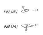
- Figs. 12(a) and 12(b) show examples of the pressure dispersion plate which is a special feature of this embodiment.
- the pressure dispersion plate 6 is of plastic material such as polystyrene, or metal such as aluminium and the like.
- the pressure dispersion plate 6 is arranged between a key-bottom 5 and a flat elastic member 140; therefore, the pressure exerted by the key-bottom 5 is not concentrated on a small area but is distributed over the surrounding region. As a result, even if the axis of slider 3 is not aligned with that of contact portion 110 after assembly of the push switch, the pressure is effectively transmitted to the contact portion 110.
- the above advantage is particularly beneficial when a plurality of push switches are combined to form a keyboard.
- the key-bottom 5 does not collide directly with the flat elastic member 140, whose life is thus remarkably improved, resulting in enhanced reliability of the keyboard.
- Figs. 12(a) and 12(b) it is also advantageous to provide means 60 for preventing a position shift of the pressure dispersion plate 6 by forming a dimple, hole, protrusion, or the like as shown in Figs. 12(a) and 12(b).
- the shape of the pressure dispersion plate 6 may be any form selected from circular, elliptic, square, rectangular and polygonal forms.
- Fig. 12(a) shows a circular form and Fig. 12(b) shows a square form.
- a plurality of domed actuators can be formed all together in a continuous form by an integral molding technique, if necessary. This will improve machining and assembling efficiencies.
- the actuator assembly including all types of domed actuators 1a to 1d and 10 described above is normally permanently fixed to the switching-element assembly 100.
- the actuator assembly may be detachably mounted such that it can be removed or replaced with another type of actuator assembly, by use of an adhesive or insertion mechanism.
Landscapes
- Push-Button Switches (AREA)
Applications Claiming Priority (2)
| Application Number | Priority Date | Filing Date | Title |
|---|---|---|---|
| JP152206/90 | 1990-06-11 | ||
| JP2152206A JPH0447616A (ja) | 1990-06-11 | 1990-06-11 | スイッチ素子 |
Publications (3)
| Publication Number | Publication Date |
|---|---|
| EP0461529A2 true EP0461529A2 (fr) | 1991-12-18 |
| EP0461529A3 EP0461529A3 (en) | 1992-08-05 |
| EP0461529B1 EP0461529B1 (fr) | 1995-07-19 |
Family
ID=15535387
Family Applications (1)
| Application Number | Title | Priority Date | Filing Date |
|---|---|---|---|
| EP91109137A Expired - Lifetime EP0461529B1 (fr) | 1990-06-11 | 1991-06-04 | Bouton-poussoir avec dispositif de commande amélioré |
Country Status (6)
| Country | Link |
|---|---|
| US (1) | US5152392A (fr) |
| EP (1) | EP0461529B1 (fr) |
| JP (1) | JPH0447616A (fr) |
| KR (1) | KR950009024B1 (fr) |
| CA (1) | CA2044009C (fr) |
| DE (1) | DE69111308T2 (fr) |
Cited By (7)
| Publication number | Priority date | Publication date | Assignee | Title |
|---|---|---|---|---|
| EP0558301A1 (fr) * | 1992-02-27 | 1993-09-01 | Fujitsu Limited | Clavier à poussoir amélioré |
| FR2755534A1 (fr) * | 1996-11-06 | 1998-05-07 | Apem | Element formant bouton-poussoir electrique |
| WO2001040914A3 (fr) * | 1999-11-30 | 2002-03-07 | Vercel Dev Corp | Navigateur internet portatif a clavier pliant |
| DE102004021542B4 (de) * | 2003-05-08 | 2006-07-13 | Lear Corp., Southfield | Modulares Schaltsystem |
| GB2434487A (en) * | 2006-01-18 | 2007-07-25 | Matsushita Electric Industrial Co Ltd | Input device |
| GB2445772A (en) * | 2007-01-18 | 2008-07-23 | Powered Triangle Ltd | A switch assembly for use in an item of footwear |
| GB2472902A (en) * | 2009-08-17 | 2011-02-23 | Paten Wireless Technology Inc | Air cushioned key switch |
Families Citing this family (31)
| Publication number | Priority date | Publication date | Assignee | Title |
|---|---|---|---|---|
| DE69133106T2 (de) * | 1990-10-30 | 2003-04-30 | Teikoku Tsushin Kogyo Co. Ltd., Kawasaki | Taste und Verfahren zur Herstellung der Taste |
| JP3498429B2 (ja) * | 1995-06-27 | 2004-02-16 | 松下電器産業株式会社 | プッシュスイッチ |
| US8610674B2 (en) * | 1995-06-29 | 2013-12-17 | Apple Inc. | Programmable tactile touch screen displays and man-machine interfaces for improved vehicle instrumentation and telematics |
| JP4037483B2 (ja) * | 1997-04-14 | 2008-01-23 | ポリマテック株式会社 | シート状キートップおよびその製造方法 |
| US5813777A (en) * | 1997-05-09 | 1998-09-29 | Bonnstauffer; Bill | Stress relieving keys |
| US6768075B2 (en) * | 2002-05-31 | 2004-07-27 | Teac Corporation | Membrane switch and dial operation member equipped therewith |
| US7285098B2 (en) * | 2002-09-05 | 2007-10-23 | Sure-Shot Medical Device, Inc. | Device for medical percussion |
| EP1429355A1 (fr) * | 2002-12-09 | 2004-06-16 | IEE INTERNATIONAL ELECTRONICS & ENGINEERING S.A. | Element de commutation en forme de feuille |
| US6770824B1 (en) * | 2003-10-22 | 2004-08-03 | Hewlett-Packard Development Company, L.P. | Buckling key caps and method |
| JP4564556B2 (ja) * | 2008-08-07 | 2010-10-20 | アルプス電気株式会社 | 押下操作型スイッチ装置 |
| EP2301704B1 (fr) * | 2009-09-11 | 2019-10-09 | TBi Industries GmbH | Chalumeau de soudage manuel |
| JP2012129140A (ja) * | 2010-12-17 | 2012-07-05 | Sony Corp | キーボードおよび電子機器 |
| TWI420553B (zh) * | 2011-06-10 | 2013-12-21 | Primax Electronics Ltd | 具有剪刀式連接元件之按鍵結構 |
| WO2012173593A1 (fr) * | 2011-06-13 | 2012-12-20 | Bell Helicopter Textron Inc. | Transmission de signal élastomère et amplification de mouvement |
| US9058941B2 (en) * | 2012-08-20 | 2015-06-16 | Apple Inc. | Floating switch assemblies and methods for making the same |
| US9793071B2 (en) * | 2013-03-07 | 2017-10-17 | Apple Inc. | Dome switch stack and method for making the same |
| US9793070B2 (en) * | 2013-03-07 | 2017-10-17 | Apple Inc. | Dome switch stack and method for making the same |
| US9786449B2 (en) | 2013-03-07 | 2017-10-10 | Apple Inc. | Dome switch stack and method for making the same |
| EP3076270B1 (fr) * | 2013-11-26 | 2020-02-19 | LG Electronics Inc. | Clavier portatif et ensemble de haut-parleurs |
| JP6450233B2 (ja) * | 2015-03-27 | 2019-01-09 | 株式会社フジクラ | スイッチ |
| JP6224649B2 (ja) | 2015-05-13 | 2017-11-01 | ファナック株式会社 | キースイッチの構造 |
| US10403451B2 (en) | 2015-06-25 | 2019-09-03 | Shin-Etsu Polymer Co., Ltd. | Pushbutton switch member |
| CN107851530B (zh) * | 2015-07-24 | 2020-05-19 | 信越聚合物株式会社 | 按钮开关用部件 |
| US9852853B2 (en) * | 2015-10-14 | 2017-12-26 | Hewlett-Packard Development Company, L.P. | Thermally fused spacers |
| KR102423148B1 (ko) * | 2015-11-26 | 2022-07-21 | 삼성전자주식회사 | 사용자 입력을 획득하기 위한 방법 및 전자장치 |
| JP6653580B2 (ja) * | 2016-01-15 | 2020-02-26 | 富士通コンポーネント株式会社 | タッチパネル装置 |
| CN108206110A (zh) * | 2016-12-16 | 2018-06-26 | 富泰华工业(深圳)有限公司 | 按键机构及具有该按键机构的电子装置 |
| IT201700006845A1 (it) | 2017-01-23 | 2018-07-23 | B810 Soc A Responsabilita Limitata | Sensore di pressione |
| TWI702626B (zh) * | 2018-03-30 | 2020-08-21 | 英屬開曼群島商康而富控股股份有限公司 | 具有較佳按壓手感的觸控按鍵 |
| KR102598959B1 (ko) * | 2018-11-14 | 2023-11-06 | 현대자동차주식회사 | 차량용 쉬프트 바이 와이어 변속 조작장치 |
| JP2023168904A (ja) * | 2022-05-16 | 2023-11-29 | 株式会社東海理化電機製作所 | シフト装置 |
Family Cites Families (16)
| Publication number | Priority date | Publication date | Assignee | Title |
|---|---|---|---|---|
| DE1129210B (de) * | 1955-10-15 | 1962-05-10 | Clemens A Voigt | Druckabhaengiger elektrischer Membranschalter |
| DE2412931A1 (de) * | 1974-03-18 | 1975-10-02 | Bbc Brown Boveri & Cie | Druckmittelbetaetigter elektrischer tastschalter |
| US3978297A (en) * | 1975-03-31 | 1976-08-31 | Chomerics, Inc. | Keyboard switch assembly with improved pushbutton and associated double snap acting actuator/contactor structure |
| US4078257A (en) * | 1976-08-23 | 1978-03-07 | Hewlett-Packard Company | Calculator apparatus with electronically alterable key symbols |
| US4109118A (en) * | 1976-09-01 | 1978-08-22 | Victor Kley | Keyswitch pad |
| DE2902769C2 (de) * | 1979-01-25 | 1982-12-09 | Rudolf Schadow Gmbh, 1000 Berlin | Drucktastenschalter |
| US4300029A (en) * | 1980-01-09 | 1981-11-10 | W. H. Brady Co. | Remote membrane switch |
| US4446344A (en) * | 1980-02-21 | 1984-05-01 | International Freezer Corp. | Pressure operated switch including an expandable flat tube |
| US4520248A (en) * | 1980-08-15 | 1985-05-28 | Rogers Corporation | Keyboard assembly |
| US4284866A (en) * | 1980-08-25 | 1981-08-18 | Amp Incorporated | Membrane switch assembly |
| US4423294A (en) * | 1982-06-17 | 1983-12-27 | The Hall Company | Laminate switch assembly having improved durability |
| DE3240940A1 (de) * | 1982-11-05 | 1984-05-10 | Wilhelm Ruf KG, 8000 München | Taste zum schliessen elektrischer kontakte |
| US4463234A (en) * | 1983-11-02 | 1984-07-31 | Centralab Inc. | Tactile feel membrane switch assembly |
| JPS60127619A (ja) * | 1983-12-13 | 1985-07-08 | 豊田合成株式会社 | スイツチ |
| US4598181A (en) * | 1984-11-13 | 1986-07-01 | Gte Communication Systems Corp. | Laminate switch assembly having improved tactile feel and improved reliability of operation |
| GB8523923D0 (en) * | 1985-09-27 | 1985-10-30 | Bestquint Ltd | Remotely operable arrangement |
-
1990
- 1990-06-11 JP JP2152206A patent/JPH0447616A/ja active Pending
-
1991
- 1991-05-24 US US07/705,650 patent/US5152392A/en not_active Expired - Lifetime
- 1991-06-04 EP EP91109137A patent/EP0461529B1/fr not_active Expired - Lifetime
- 1991-06-04 DE DE69111308T patent/DE69111308T2/de not_active Expired - Fee Related
- 1991-06-07 CA CA002044009A patent/CA2044009C/fr not_active Expired - Fee Related
- 1991-06-08 KR KR1019910009452A patent/KR950009024B1/ko not_active Expired - Fee Related
Cited By (14)
| Publication number | Priority date | Publication date | Assignee | Title |
|---|---|---|---|---|
| EP0558301A1 (fr) * | 1992-02-27 | 1993-09-01 | Fujitsu Limited | Clavier à poussoir amélioré |
| US5486059A (en) * | 1992-02-27 | 1996-01-23 | Fujitsu Limited | Keyboard having improved keytop |
| US5560724A (en) * | 1992-02-27 | 1996-10-01 | Fujitsu Limited | Keyboard having improved keytop |
| FR2755534A1 (fr) * | 1996-11-06 | 1998-05-07 | Apem | Element formant bouton-poussoir electrique |
| EP0841674A1 (fr) * | 1996-11-06 | 1998-05-13 | Apem | Elément formant bouton-poussoir électrique |
| US6008460A (en) * | 1996-11-06 | 1999-12-28 | Apem | Element forming an electric push-button |
| WO2001040914A3 (fr) * | 1999-11-30 | 2002-03-07 | Vercel Dev Corp | Navigateur internet portatif a clavier pliant |
| DE102004021542B4 (de) * | 2003-05-08 | 2006-07-13 | Lear Corp., Southfield | Modulares Schaltsystem |
| GB2434487A (en) * | 2006-01-18 | 2007-07-25 | Matsushita Electric Industrial Co Ltd | Input device |
| GB2434487B (en) * | 2006-01-18 | 2008-05-21 | Matsushita Electric Industrial Co Ltd | Input device |
| US8339368B2 (en) | 2006-01-18 | 2012-12-25 | Panasonic Corporation | Input device |
| GB2445772A (en) * | 2007-01-18 | 2008-07-23 | Powered Triangle Ltd | A switch assembly for use in an item of footwear |
| GB2445772B (en) * | 2007-01-18 | 2009-11-11 | Powered Triangle Ltd | Switch assembly |
| GB2472902A (en) * | 2009-08-17 | 2011-02-23 | Paten Wireless Technology Inc | Air cushioned key switch |
Also Published As
| Publication number | Publication date |
|---|---|
| KR920001585A (ko) | 1992-01-30 |
| JPH0447616A (ja) | 1992-02-17 |
| DE69111308T2 (de) | 1996-01-11 |
| EP0461529A3 (en) | 1992-08-05 |
| US5152392A (en) | 1992-10-06 |
| CA2044009C (fr) | 1995-05-09 |
| DE69111308D1 (de) | 1995-08-24 |
| KR950009024B1 (ko) | 1995-08-10 |
| EP0461529B1 (fr) | 1995-07-19 |
| CA2044009A1 (fr) | 1991-12-12 |
Similar Documents
| Publication | Publication Date | Title |
|---|---|---|
| EP0461529B1 (fr) | Bouton-poussoir avec dispositif de commande amélioré | |
| US4307268A (en) | Tactile element and keyboard including the tactile element | |
| US4323740A (en) | Keyboard actuator device and keyboard incorporating the device | |
| US5150118A (en) | Interchangeable coded key pad assemblies alternately attachable to a user definable keyboard to enable programmable keyboard functions | |
| US5767464A (en) | Electronic device low profile keyboard switch assembly with deployed and stored actuating mechanism | |
| US4362911A (en) | Membrane keyboard switch assembly having selectable tactile properties | |
| US4322587A (en) | Keyboard device | |
| US20010013463A1 (en) | Two-position pushbutton switch | |
| EP0277404B1 (fr) | Clavier ayant un boîtier inférieur avec une partie intégrante surélevée pour supporter une carte à circuit imprimé | |
| US4245138A (en) | Tactile element and keyboard including the tactile element | |
| US4701579A (en) | Data entry keyboard | |
| JPH04215220A (ja) | キーボード用作動板 | |
| GB2130016A (en) | Electrical push button switch | |
| GB2133627A (en) | Membrane keyboard electrical switch | |
| US5900599A (en) | Switch for display | |
| US6259049B1 (en) | Key switch device with low-profile key top which gives three-dimensional appearance and looks thicker than actual one | |
| US5934454A (en) | Thin keyboard having multiple hinge members per keyswitch | |
| EP0157037A2 (fr) | Commutateur à bouton poussoir à longue course | |
| JPH10188727A (ja) | メンブレンスイッチ | |
| EP0396963A2 (fr) | Sous-ensemble à touches codé interchangeable, pouvant être fixé alternativement à un clavier configurable par l'utilisateur, pour effectuer des fonctions de clavier programmables | |
| JPH06103851A (ja) | フラットキーボード用メンブレンスイッチ | |
| JP3031058B2 (ja) | キーボード | |
| US5032695A (en) | Membrane switch with movable and fixed flap contacts mounted on a common dielectric substrate | |
| CA1155889A (fr) | Touche de clavier a dispositif d'actionnement encastre | |
| JPH0227471Y2 (fr) |
Legal Events
| Date | Code | Title | Description |
|---|---|---|---|
| PUAI | Public reference made under article 153(3) epc to a published international application that has entered the european phase |
Free format text: ORIGINAL CODE: 0009012 |
|
| AK | Designated contracting states |
Kind code of ref document: A2 Designated state(s): DE FR GB IT NL |
|
| PUAL | Search report despatched |
Free format text: ORIGINAL CODE: 0009013 |
|
| AK | Designated contracting states |
Kind code of ref document: A3 Designated state(s): DE FR GB IT NL |
|
| 17P | Request for examination filed |
Effective date: 19920826 |
|
| 17Q | First examination report despatched |
Effective date: 19940429 |
|
| GRAA | (expected) grant |
Free format text: ORIGINAL CODE: 0009210 |
|
| AK | Designated contracting states |
Kind code of ref document: B1 Designated state(s): DE GB NL |
|
| REF | Corresponds to: |
Ref document number: 69111308 Country of ref document: DE Date of ref document: 19950824 |
|
| EN | Fr: translation not filed | ||
| PLBE | No opposition filed within time limit |
Free format text: ORIGINAL CODE: 0009261 |
|
| STAA | Information on the status of an ep patent application or granted ep patent |
Free format text: STATUS: NO OPPOSITION FILED WITHIN TIME LIMIT |
|
| 26N | No opposition filed | ||
| REG | Reference to a national code |
Ref country code: GB Ref legal event code: IF02 |
|
| PGFP | Annual fee paid to national office [announced via postgrant information from national office to epo] |
Ref country code: DE Payment date: 20070531 Year of fee payment: 17 |
|
| PGFP | Annual fee paid to national office [announced via postgrant information from national office to epo] |
Ref country code: NL Payment date: 20070617 Year of fee payment: 17 |
|
| PGFP | Annual fee paid to national office [announced via postgrant information from national office to epo] |
Ref country code: GB Payment date: 20070530 Year of fee payment: 17 |
|
| GBPC | Gb: european patent ceased through non-payment of renewal fee |
Effective date: 20080604 |
|
| NLV4 | Nl: lapsed or anulled due to non-payment of the annual fee |
Effective date: 20090101 |
|
| PG25 | Lapsed in a contracting state [announced via postgrant information from national office to epo] |
Ref country code: DE Free format text: LAPSE BECAUSE OF NON-PAYMENT OF DUE FEES Effective date: 20090101 |
|
| PG25 | Lapsed in a contracting state [announced via postgrant information from national office to epo] |
Ref country code: NL Free format text: LAPSE BECAUSE OF NON-PAYMENT OF DUE FEES Effective date: 20090101 |
|
| PG25 | Lapsed in a contracting state [announced via postgrant information from national office to epo] |
Ref country code: GB Free format text: LAPSE BECAUSE OF NON-PAYMENT OF DUE FEES Effective date: 20080604 |